

Page 1
AN2044
APPLICATION NOTE
OPERATING PRINCIPALS FOR PRACTISPIN
STEPPER MOTOR MOTION CONTROL
1 REQUIREMENTS
In operating a stepper motor system one of the most common requirements will be to execute
a relative move. The move will usually be specified as a fixed number of basic motor steps in
the clockwise or counter-clockwise direction. It is common practice to execute this move along
a trapezoidal shaped velocity vs. time profile.
This profile is determined by the number of steps to be moved and the required accel, decel,
and peak speed. Very often sys tem designers require that a move be made in the shortest
time possible and in these cases the accel, decel and peak speed are set to the maximum that
the system can achieve.
Given the move distance, accel, decel, and peak speed requirement, a profile can be determined. Since the control structure of the practispin software is designed such that the velocity
and accel/decel rate can be changed at will, the task of pre-calculating the velocity profile boils
down to determining the position values where operation switches from accel to constant
speed and then from constant speed to decel. Since this is a relative move, we can assume
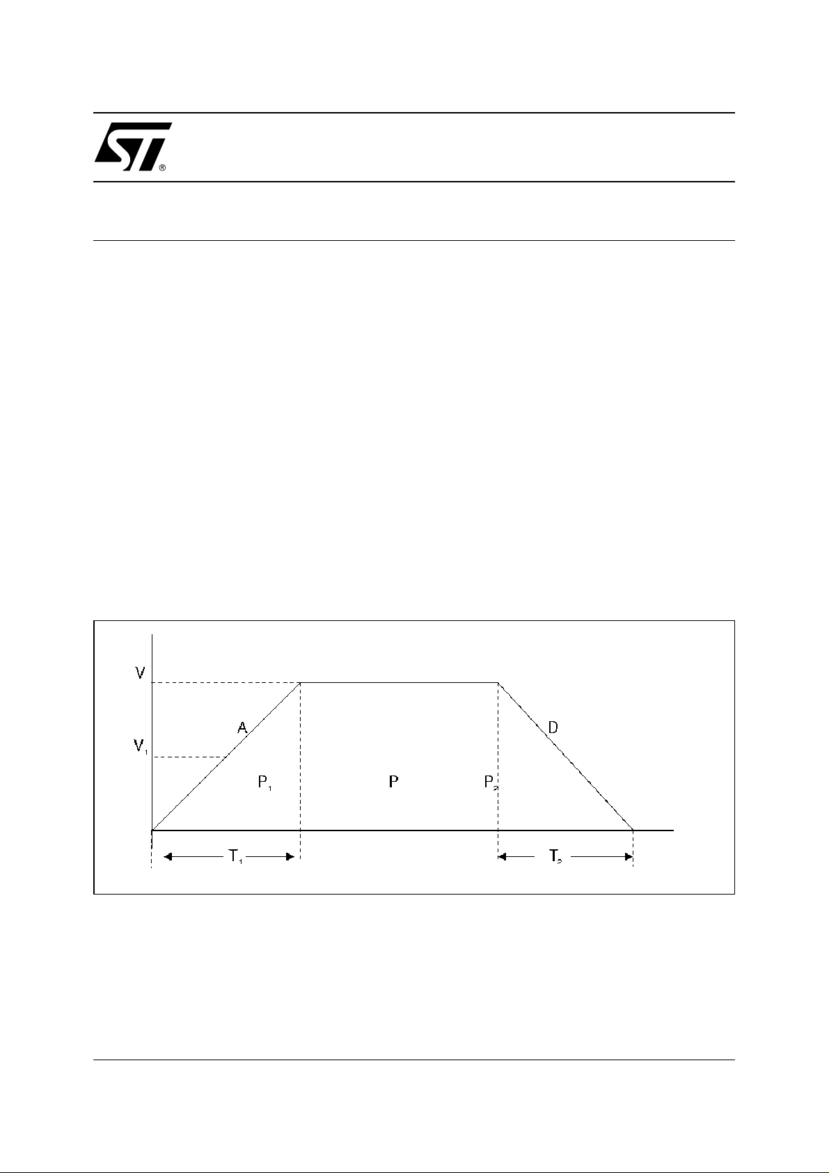
that motion starts at position = 0, ti me = 0, and v elocity = 0. Figure 1 shows a ty pical trapezoi dal velocity vs. time profile
Figure 1. Trapezoidal Velocity vs. Time Profile
Let: P = total move distance in steps
P1 = steps required to accel from 0 to V
P2 = steps required to decel from V to 0
V = peak velocity in steps per second (steps/sec)
V1 = average velocity during accel or decel
AN2044/0904
Rev. 1
1/9
Page 2
AN2044 APPLICATION NO TE
A = required accel rate in steps per second per second (steps/sec2)
D = required decel rate in steps per second per second (steps/s ec2)
T1 = acceleration time in seconds
T2 = deceleration time in seconds
2 TRAPEZOIDAL POSITION FORMULAS
If we assume that the velocity will rise from 0 to V at a constant rate of acceleration:
1) T1 = V / A
2) V1 = V / 2
3) P1 = V1 T1
Substituting 1 and 2 into 3 yields:
4) P1 = V2 / 2A
In the same manner we have:
5) P2 = V2 / 2D
Once P1 and P2 have been calculated a check can be made to determine whether a trapezoidal profile is possible or whether a triangular move must be made instead. If the total number
of steps required to accel and decel ( P1 + P2 ) is less than the total m ove distance, P , then
there will be some "room" left for a constant velocity portion of the profile. If, on the other hand,
P1 + P2 is greater than P, then the move profile cannot be allowed to get up to the requested
speed since just getting up to speed and back down (at the requested accel and decel) would
cause a move that would overshoot the target position.
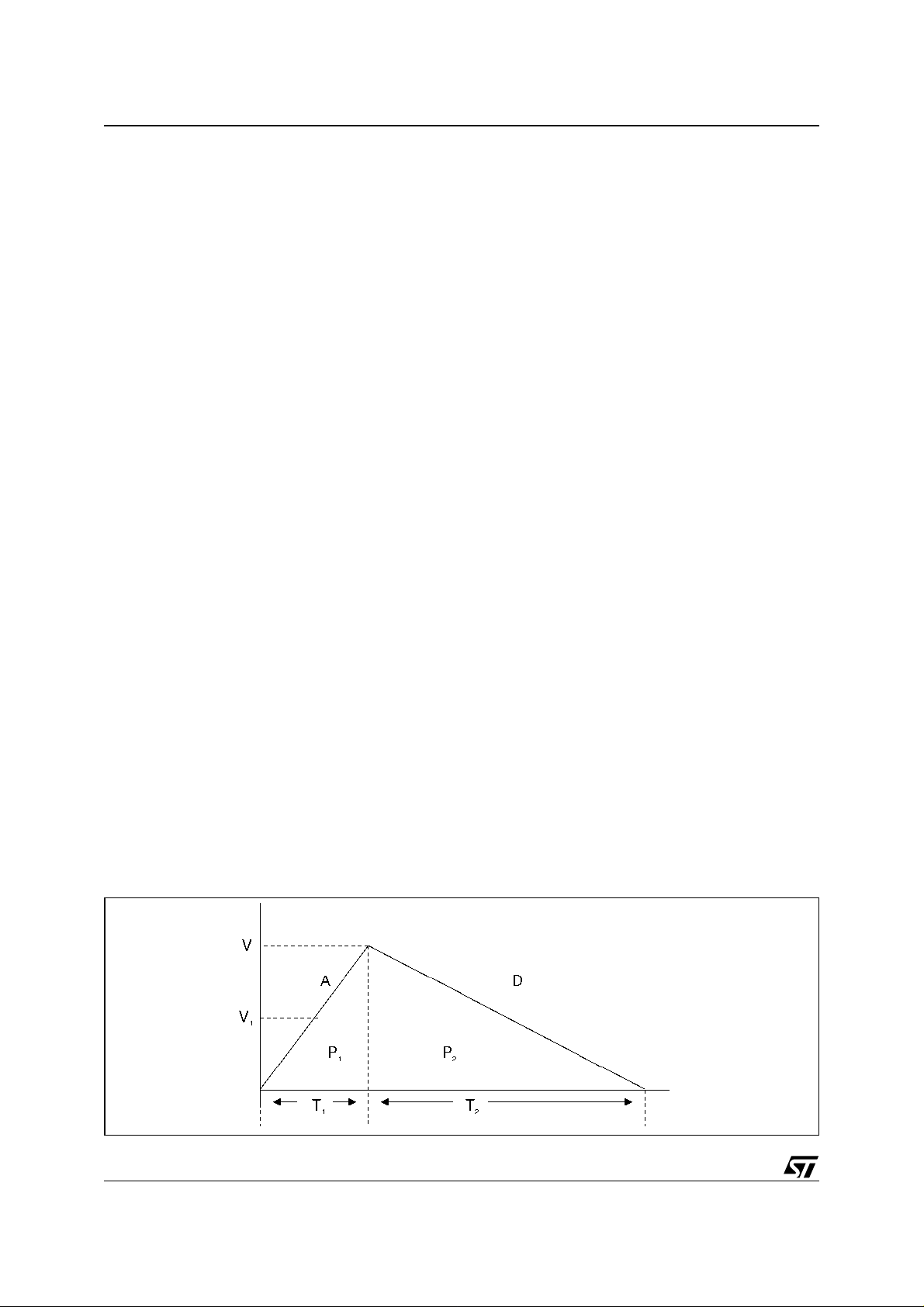
If P1 + P2 is greater than P then a triangular rather than trapezoidal profile must be projected.
With a triangular velocity profile there is no constant velocity portion of the move.
The motor will accelerate at A and then abruptly switch to decelerating at D in order to "land"
at the desired position at zero speed. In the case of a triangular profile we have only one im-
portant parameter to calculate, that being the motor position at which the system must switch
from accel to decel mode.
The calculation is, however, somewhat more complicated than the trapezoidal case. Figure 2
shows a typical triangular velocity vs. time profile.
Figure 2. Triangular Velocity vs. Time Profile
2/9
Page 3

AN2044 APPLICATION NOTE
3 TRIANGULAR POSITION FORMULAS
In a triangular move, the total distance is the distance to accel plus the distance to decel:
6) P = P1 + P
Substituting 4 and 5 into 6 yields:
7) P = V2 / 2A + V2 / 2D
Multiplying both sides of 7 by 2AD to clear fractions yields:
8) 2ADP = DV2 + AV2
2
Extracting the common factor V2 on the RHS of 8 yields:
2
9)2ADP = V
( D + A )
Dividing both sides of 9 by 2A( A + D) yields:
2
10)DP / ( A + D ) = V
/ 2A
Substituting 4 into 10 and re-arranging yields:
11)P1 = PD / ( D + A )
Equation 11 is our final result and is the most convenient form o f the formula for calculating
the position at which the mode must be switched from accel to dec el for a triangular move.
Please note also that this formula passes a fundamental "sanity" test.
If the accel and decel rates are equal, then P1 = P / 2.
This is intuitively obvious. The system would have to spend half the total distance accelerating
and the other half decelerating.
As the decel rate is increased, we can spend more time accelerating before we have to "put
on the brakes" to come to a stop at the required position.
The Practispin stores P, D, and A as unsigned 16 bit variables. A 16 by 16 multiply subroutine
is used to get the product PD, which is 32 bit.
A 32 by 16 divide subroutine is used to get the quotient of PD and ( D + A ). Note: If ( D + A )
overflows 16 bits then both terms are pre-divided by 2 before the main divide is executed.
The same subroutines are used to calculate formulas 4 and 5 in the trapezoidal case. Please
note that execution time for these calculations is not critical since they are done only once per
move and are completed before the move begins.
4 PRACTISPIN STEPPER MOTOR CONTROL SCHEME
4.1 20 KHZ INTERRUPT
The heart of the stepper motor c ontrol mechanism is the 20KHZ interrupt. This interrupt invokes an Interrupt Service Routine (ISR) which executes repeatedly on a fixed time interval of
50 microseconds. In the subsequent discussion we will call this 50 microsecond interval a
TICK and this will serve as our basic time unit.
In order to maintain a consistent system of units we w ill meas ure position in steps, v e locity in
steps/tick, and acceleration/deceleration in steps/tick
amount to a real time simulation of the motion system. The ISR calculates real time values for
2
. The calculation performed by the ISR
3/9
Page 4

AN2044 APPLICATION NO TE
velocity and position given the commanded acceleration (or decel) and the present values for
velocity and position.
4.2 MOTION SIMULATION FORMUL AS
It is well known from basic physics that velocity is the time integral of acceleration and position
is, in turn, the time integral of velocity. Since the ISR executes once each time TICK it can
calculate the system variables in real time by implementing the following equations:
SPD = SPD + ACC
POS = POS + SPD
Where:
SPD is motor velocity in steps / tick
ACC is commanded motor acceleration in steps / tick
2
POS is motor position in steps
This simulation does a "flat topped" integral approximation. Since the time interval for the simulation is so short ( 50µSEC ) compared to the time scale of the moving system, this crude
approximation is sufficiently accurate. Internally these three key variables are represented as
multiple precision integers (the ST7 is, after all, an 8 bit processor) with a fixed "binary point".
The naming convention used for the memory bytes which make up each variable is to use the
basic name (POS, SPD, or ACC) plus a suffix of one digit to show the significance of the byte.
0 for the lsb, 1 for the next, etc. Table1 shows the individual bytes that make up the three variables and their relative scaling. The * represents the "binary point" of each variable.
While the binary weighting of the bi ts to the l eft of the bi nary poi nt ar e the tr aditional powers of
2 (1,2,4,8, etc) the weighting of the bits to the right of the binary point are the successive negative powers of 2 ( ½, ¼, 1/8, etc.).
In the case of the state variable ACC, ACC2 and beyond are not even implemented because
we will never encounter acceleration values that large. This is because of the selection of units
needed to speed the calculations and provide a uniform system.
An actual value of 1 step/tick
2
(ACC3 = 1 and the rest set to zero) would be a very great ac-
celeration indeed:
2
1 step/tick
= 20,000 steps/tick per second (20,000 ticks in a second)
= 400 X 106 steps/sec2
= 120 X 10
6
RPM/sec !! (assuming 200 steps per rotation)
With the scaling as implemented in the Practispin, the smallest accel value (ACC0=1 and
ACC1 = 0) is equivalent to 7.153 RPM per second, a much more reasonable value. The maximum value for SPD is 16,777,215 / 16,777,216 (let's call it 1) s tep / tick which is equal to
20,000 steps / second or 6,000 RPM. Generally speaking, stepper motors just don't go that
fast. POS maxxes out at 65,535.999985 steps ( w ith a resolution of 1/65536 of a step). This
is 327.68 rotations for a 200 step/rot motor.
4/9
Page 5

AN2044 APPLICATION NOTE
Table 1. State Variable Representation
POS3 POS2 * POS1 POS0
* SPD2 SPD1 SPD0
* ACC1 ACC0
In its simplest form this system executes a trapezoidal move by the following steps:
1) Calculate the motor position values ( P1 and P-P2 using the formulas derived above ) at which
the system should transition from accel to constant speed and then from constant speed to decel.
2) Set the POS and SPD variables to zero, set ACC to the required value, and then start up the
ISR. The ISR will update SPD by adding ACC0 into SPD0, ACC1 into SPD1 (plus a possible
carry from previous), and then inc SPD2 if there was a carry out of ACC1 + SPD1. POS is updated by adding SPD1 into POS0, SPD2 into POS1 (with carry), then inc POS2 if SPD2 + POS1
produced a ca rry and finally inc POS3 if POS2 rolls over.
3) Whenever POS2 increases (it could never increase by more that 1 because of the small time
tick), advanc e the motor by one step.
4) Wh en the in teger part (PO S3: P OS2) of POS mat ches P 1, s et A CC to zero to e nter the cons tant
velocity reg ion. Speed will hold constant but position will con tin ue t o inc rease.
5) Wh en PO S match es P-P2 , change t he value in ACC fro m zero to t he requir ed decel setting an d
start subtrac ting into SPD instea d of adding.
6) Wh en POS mat ches P , s et ACC a nd SPD to zero ( SPD sho uld alr ead y be the re ), st op s teppin g
the motor, and hold position.
In step 3 of the procedure for executing a trapezoidal move it was stated that we must "advance the motor by one step". Lets examine the details required to accomplish this. First, let's
describe how a bipolar, two phase stepper motor is commutated or stepped.
The motor has two windings (A and B) each of which may be in one of three states: Positive,
Negative, or Off based on the direction of current flow, if any, through the coil. The conventional half step commutating sequence is described in figure 4. After step #7 the sequence repeats back from 0. Table 2 presents a graphical display of the current in the motor coils vs.
motor step.
Table 2. Half Step Commutating Sequence
STEP # COIL A COIL B IN1A IN2A ENA IN1B IN2B ENB
0POSNEG101011
1POSZERO101XX0
2POSPOS101101
3ZEROPOSXX0101
4 NEG POS 0 1 1 1 0 1
5NEGZERO011XX0
6NEGNEG011011
7ZERONEGXX0011
5/9
Page 6

AN2044 APPLICATION NO TE
Figure 3. Motor Phase Currents vs. Step Number
Table 2 also includes the required states for the six logic inputs of the L6207 Stepper Motor
Driver. In order to understand the details of this typical driver chip some background on the
characteristics of the L6207 are required.
4.3 L6207 DUAL FULL BRIGDE DRIVER
A typical stepper motor driver is the L6207 and we will use thi s part as an example to illus trate
the operation of the Practispin system. The L6207 includes two independent full or H bridges
with separate control inputs and current limit functions. The two bridges are designated A and
B and their output pins designated as OUT1A, OUT2A, OUT1B, and OUT2B. These outputs
are controlled independently by logic inputs IN1A, IN2A, IN1B, and IN2B respectively. A logic
high or low on any of these inputs will drive its corresponding output to the positive supply rail
or to ground.
Both of the A outputs will be forced to an off (high impedance) state if the ENA pin is taken
logic low, as will the B outputs if ENB is taken low.
The L6207 is thus controlled by six logic inputs: IN1A, IN2A, and ENA controlling bridge A and
IN1B, IN2B, and ENB controlling bridge B. Each bridge also has an analog control signal,
VREFA and VREFB, which contro l the cu rrent limit se tting.
4.4 STEP STATE
If we know the state of the stepper motor (a number from 0 to 7) then we can use figure 4 to
tell us what logic levels to apply to the control pins of the L6207. The actual state is determined
by a byte variable of the Practispin program called stepstate. Stepstate is initialized to zero on
power up or whenever the power bridge is disabled. Stepstate is incremented whenever the
driving algorithm requires us to "advance the motor". Since eight commutating steps divides
evenly into the natural 256 count of a byte variable, stepstate is just continually incremented
and allowed to roll over. We only consider the lower three bits to be significant. Now, armed
with the stepstate variable, it is a simple matter to construct a lookup table. We will use stepstate (logically anded with a mask to clear all but the low three bits) as the index into a table
which will provide the data to be written out to the L6207. Table 3 shows the hardware map-
6/9
Page 7

AN2044 APPLICATION NOTE
ping of the port B data bits onto the L6207 control pins. Following T able 3 is the ac tual lookup
table from the ST7 source code.
Table 3. Hardware Mapping of Port B
D7 D6 D5 D4 D3 D2 D1 D0
X ENA IN1A IN2B IN1B IN2A X ENB
Table 4. halfsteptable
dc.b %01110001;0+ dc.b %01111000;1+ 0
dc.b %01101001;2+ +
dc.b %00101101;30 +
dc.b %01001101;4- +
dc.b %01011100;5- 0
dc.b %01010101;6- dc.b %00110101;70 -
4.5 HALFS TEP, FULLSTEP, R EVERSE
In the Practispin program, whenever the stepstate in incremented, a new bit pattern is read
from the table and output to port B. If we prefer to full step the motor rather that half step, then
we need only to shift the stepstate by one bit left (multiply by 2) i m mediately before we mask
off the three low bits and do the table lookup. This will yield only the values 0, 2, 4, and 6 and
these are the only states that will be entered.
Please note as shown in Table 2 that these four states do not include a zero state for either
phase as both coils are always energized. If we wish to operate the motor in the other direction
it is only necessary to change the increments of stepstate to decrements. We will then run
backwards through the commutating table and the motor will follow in the reverse direction.
7/9
Page 8

AN2044 APPLICATION NO TE
Table 5. Revision History
Date Revision Description of Changes
September 2004 1 First Issue
8/9
Page 9

AN2044 APPLICATION NOTE
The present note which i s for guidance only, aims at providing customers with information reg arding their pr oducts in
order for them to save time. As a result, STMicroelectronics shall not be held liable for any direct, indirect or
consequentia l damages with respect to any claims ar ising from the content of such a no te and/or the use made by
customers of the information contained herein in connection with their products.
Information furnished is believed to be accurate and reliable. However, STMicroelectronics assumes no responsibility for the consequences
of use of such information nor for any infringement of patents or other rights of third parties which may result from its use. No license is granted
by implic ation or otherwise under an y patent or patent r i ghts of ST M i croelectr oni cs. Specifications menti oned in th i s publicati on are subject
to change without notice. This publication supersedes and replaces all information previously supplied. STMicroelectronics products are not
authorized for use as c ritical components in li fe support devices or sy st em s without express wri t ten approval of STMic roelectronics.
The ST logo is a registered trademark of STMicroelectronics.
All other nam es are the property of their resp ective owne rs
© 2004 STMi croelectronics - All ri ghts reser ved
Australi a - Belgium - B razil - Canada - China - C zech Republ i c - Finland - F rance - Germany - Hong Kong - India - Israel - It al y - Japan -
Malaysia - M al ta - Morocco - Singapo re - Spain - Sweden - Switzerland - United Kingdom - Un i ted States of Am erica
STMicroelectronics group of companies
www.st.com
9/9
 Loading...