

Page 1

AN2030
APPLICATION NOTE
BACK EMF DETECTION
DURING PWM ON TIME BY ST7MC
INTRODUCTION
The direct back EMF sensing scheme used by ST72141 synchronously samples the motor
back EMF during PWM “off” time without the need to sense or re-construct the motor neutral
in a sensorless BLDC motor drive system. Since this direct back EMF sensing scheme re
quires minimum PWM “off” time to sample the back EMF signal, the duty cycle can't reach
100%. Also in some applications, i.e. HVAC using high inductance motors, we see the zero
crossing detection is unsymmetrical in the ST72141 sensorless drive system at high speed. It
is found that the long settling time of a parasitic resonant between the motor inductance and
the parasitic capacitance of power devices causes false zero crossing detection of back EMF.
This application note provides an analysis of the resonant transient during PWM “off” time. As
a result, the back EMF detection during PWM “on” time is used in ST7MC to solve the
problem.
-
AN2030 Rev 2 1/13
1
Page 2
BACK EMF DETECTION DURING PWM ON TIME BY ST7MC
1 TRANSIENT ANALYSIS DURING PWM OFF TIME
Generally, a brushless dc motor is driven by a three-phase inverter with what is called six-step
commutation. The conducting interval for each phase is 120° by electrical angle. Therefore,
only two phases conduct current at any time, leaving the third phase floating. This opens a
window to detect the back EMF in the floating winding.
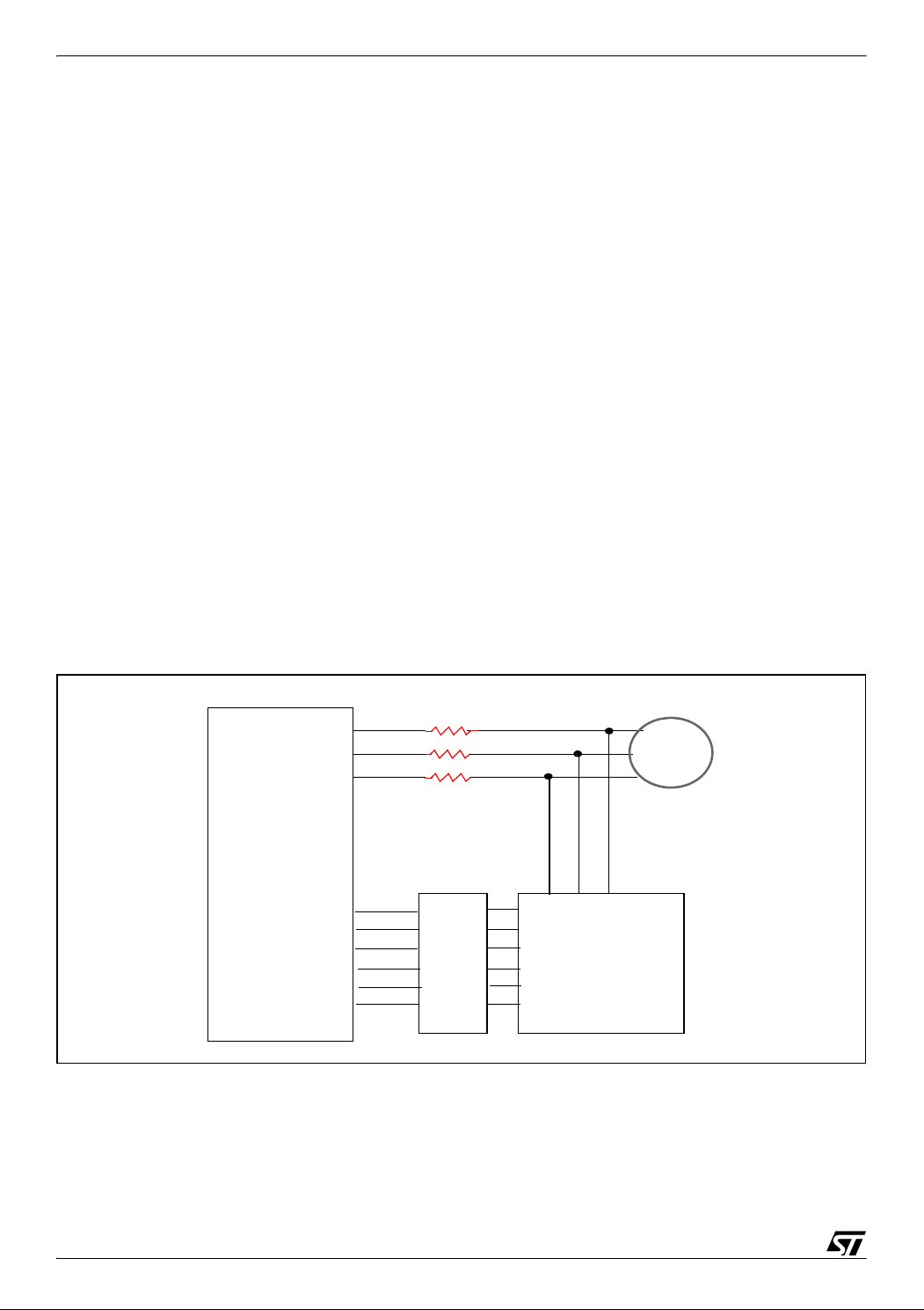
For the direct back EMF sensing scheme, the PWM signal is applied on high side switches
only, and the back EMF signal is synchronously sampled during the PWM off time. The low
side switches are only switched to commutate the phases of the motor. The true back EMF
can be detected during off time of PWM because the terminal voltage of the motor is directly
proportional to the phase back EMF during this interval. Also, the back EMF information is ref
erenced to ground, which eliminates the common mode noise; and the synchronous sampling
rejects the high-frequency switching noise. Only three resistors are required to detect the back
EMF, as shown in
Ideally, the terminal voltage for the floating phase is directly proportional to the back EMF
signal in steady state during PWM off time
Figure 1.
v
abc,,
[1]. The equation is as following:
3
-- -
e
=
abc,,
2
(1)
-
Where Vx is the terminal voltage, ex is the back EMF of the floating phase.
Figure 1. Direct Back EMF Sensing block diagram
Back EMF Sensing
MCIC
MCIB
MCIA
ST72141
MC00
MC01
MC02
MC03
MC04
MC05
Microcontroller
R1
R2
R3
Gate drive
motor
Power stage
The equation (1) is valid only in steady state.
2/13
2
Page 3

BACK EMF DETECTION DURING PWM ON TIME BY ST7MC
Considering the parasitic capacitance C
will have some transition time during PWM off time.
in the switches, the voltage in the floating phase
oes
Figure 2 shows the circuit where the PWM
is applied to phases A and B while phase C is floating.
Figure 2. Phase C is floating
Vdc
C
oes
Va
Vb
Vc
C
oes
GND
r
r
r
L
L
L
e
a
e
b
Vn
e
c
We can simplify the circuit by using the neutral voltage Vn=1/2 * ec during PWM off time [1]
and during PWM on time (see next chapter) to get the equivalent circuit in Figure 3.
Figure 3. Simplified equivalent circuit when phase C is floating
3
e
c
Vc
2*C
r
oes
When PWM is on in phase A and B, the terminal voltage in steady state will be:
1
-- -
v
c
2
3
-- -
v
dc
e
+=
c
2
which is the initial condition in the capacitor during PWM off time.
L
2
(2)
3/13
Page 4
BACK EMF DETECTION DURING PWM ON TIME BY ST7MC
C
is not a fix value for IGBTs, which depends on the voltage. Figure 4 shows the curve for
oes
STGB7NB60HD.
Figure 4. C
oes
curve
Assuming the back EMF has just passed the rising edge of the zero crossing. When PWM is
off, the voltage across the capacitor will be discharged in a resonant way.
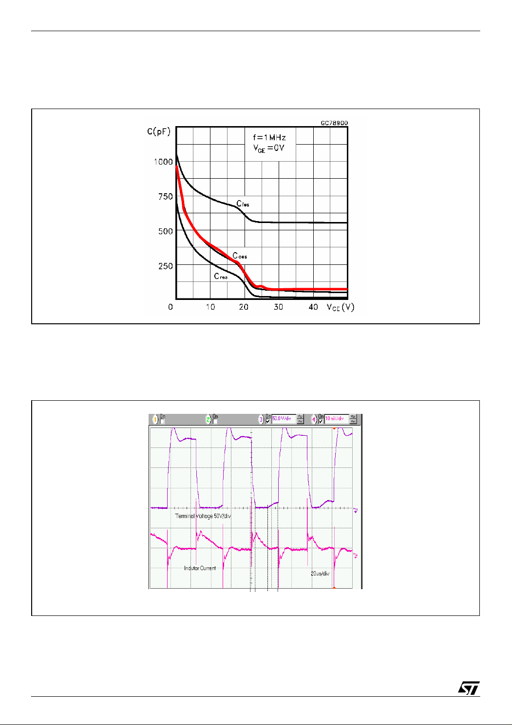
Figure 5 shows a
terminal voltage and the current waveform.
Figure 5. Waveform of floating phase terminal voltage and inductor current
10mA/div
10mA/div
t2
t1 t1’
t1 t1’
t2
t0
t0
At the time t0, PWM is off.
4/13
Page 5

BACK EMF DETECTION DURING PWM ON TIME BY ST7MC
t0~t1: The capacitor starts to discharge by the inductance. At the beginning, since the capac-
itance is small, the discharging rate is very fast, but as the voltage reduces, the rate drops. At
time t1, the capacitor is fully discharged, and the diode D turns on. The current passes through
the diode and the voltage is kept around -0.7v.
t1~t1': The current will decrease linearly from peak to zero because the inductor is reset by
(Vd+3/2ec). Vd is the voltage drop of the diode. Large inductance will keep the clamp time
longer. At time t1', the inductor current is reset to zero. The back EMF signal shows up in the
winding terminal.
Since the back EMF is detected at the end of PWM off period, which is at t2, it is important that
the clamp should be ended before t2; otherwise the controller won't be able to detect the zero
crossing. Because of the settling time of the resonant transient during PWM off time, the max
imum PWM duty is far from 100% duty cycle.
If the back EMF can be detected during on time at high duty cycle, then there is enough time
for the resonant transient to settle down. The next chapter explains how to implement it.
-
5/13
Page 6

BACK EMF DETECTION DURING PWM ON TIME BY ST7MC
2 BACK EMF DETECTION DURING PWM ON TIME
For ST7MC, it is possible to detect the back EMF during PWM on time. At high speed operation (high duty cycle), the controller can detect the back EMF at the end of PWM on time. In
this way, the controller avoids the resonant transition time. At low speed operation (low duty
cycle), the controller can detect the back EMF at the end of PWM off time. It still has the ben
efit of no attenuation of back EMF.
First, we can derive the floating phase terminal winding voltage during PWM on time. Assume
phase A and B are conducting current, phase C is floating.
Figure 6. Circuit model during PWM on time
Vdc
Vdc
L
Va
Va
L
r
r
e
e
a
a
-
Vb
Vb
i
i
GND
GND
From phase A, we have
v
v
n
dc
From phase B, we have
v
ri L
n
Voltage drop on power devices is ignored.
From (3) and (4),
v
dc
-------
v
n
2
– e
ri– L
di
---- -
+=
dt
e
aeb
----------------–=
dt
---- -
dt
+
2
Vc
Vc
e–
b
(3)
(4)
(5)
L
L
L
L
r
r
rr
r
–=
a
e
e
e
e
b
b
Vn
Vn
c
c
6/13
Page 7

BACK EMF DETECTION DURING PWM ON TIME BY ST7MC
v
Also from the balance three-phase system, considering fundamental frequency only, we have
eaebe
++ 0=
c
(6)
From (5) and (6),
e
v
dc
-------
v
n
c
----+=
2
2
(7)
So, the terminal voltage Vc,
v
3
ecv+
c
-- -
n
2
dc
e
-------+==
c
2
(8)
During PWM on time, if the terminal voltage is compared to half of the dc voltage, the zero
crossing of the back EMF is able to be detected.
The following implementation is based on the ST7MC starter kit.
Figure 7. Hardware implementation
Back EMF Sensing
R43
R54
R7
R44
R50
motor
Vdc
MCIC
MCIB
MCIA
PE1
PE2
PE3
MCVREF
R4
R5
R9
R49
R53
R6
R8
MC00
MC01
MC02
ST7MC
MC03
MC04
MC05
Gate drive
Power stage
At low PWM duty cycle, PE1, PE2 and PE3 are configured as floating input. There is no attenuation for the signals since R4, R5 and R6 connect to the floating points. The microcontroller
detects the zero crossing of the back EMF during PWM off time. The reference voltage is in
ternally set. Then at high duty cycle, PE1, PE2 and PE3 are re-configured as output, set to
logic low. All signals are then attenuated by resistor ratio. Meanwhile, the microcontroller will
use external voltage, attenuated dc bus voltage Vdc, as the reference for zero crossing detec
tion.
In the starter kit, R43=R44=R49=R50=R53=R54=82k. We should select appropriate resistors
for different dc voltage, as shown in the following table.
7/13
-
-
Page 8

BACK EMF DETECTION DURING PWM ON TIME BY ST7MC
Table 1. Table Resistor selection
Vdc (V) R4 (k) R5(k) R6(k) R7(k) R8(k) R9(k) Vref(V)
12 100 100 100 150 4.3 36 2.27
24 33 33 33 160 4.7 15 2.00
48 16 16 16 240 18 12 2.13
165 4.7 4.7 4.7 330 2.7 4.7 2.30
330 2.2 2.2 2.2 430 330 5.1 2.20
It is preferred to use 1% resistors. But the performance will be acceptable using 5% resistors.
D16, D17, D18, R45, R51, and R55 in the starter kit can be removed if this new scheme is
used.
Figure 8 shows the comparison of back EMF detection during off time vs on time. If the back
EMF is detected during off, there is no attenuation. The signal is clamped at 5v. If the back
EMF is detected during PWM on time, the signal is attenuated.
Figure 8. (A) Waveforms for back EMF detection during PWM off time; (B) waveforms for
back EMF detection during PWM on time.
(A) (B)
Figure 9 shows the detailed waveform of the zero crossing when the back EMF is detected
during PWM on time. From the waveform, we can see that the zero crossing is detected at the
end of PWM on time.
8/13
Page 9

BACK EMF DETECTION DURING PWM ON TIME BY ST7MC
Figure 9. (A) Rising edge of zero crossing for back EMF detection during on time; (B)
falling edge of zero crossing for back EMF during on time.
(A) (B)
Figure 10 demonstrates that the system is able to run at 100% duty cycle, and the zero
crossing happens at the half of the dc bus voltage.
Figure 10. Waveforms for 100% duty cycle operation.
The software needs some modification as well, which is listed in the appendix.
9/13
Page 10

BACK EMF DETECTION DURING PWM ON TIME BY ST7MC
3 CONCLUSION
The original direct back EMF sensing scheme has the limitation of duty cycle since it requires
minimum PWM off time to do the detection. The resonant transient caused by motor induct
ance and power devices' parasitic capacitance will further limit the duty cycle. The improved
direct back EMF sensing scheme, which does the back EMF sensing during PWM on time,
eliminates the duty cycle limitation. It can run at 100% duty cycle, and avoid the parasitic res
onant transient. During motor start-up and low speed, it is preferable to use the original
scheme since there is no signal attenuation; while at high speed, the system can switched to
the improved back EMF sensing scheme. With the combination of two detection schemes in
one system, the motor can run very well over a wide speed range.
4 REFERENCE
[1] [J.Shao, D.Nolan, and T.Hopkins, “A Novel Direct Back EMF Detection for Sensorless
Brushless DC (BLDC) Motor Drives,” Applied Power Electronic Conference (APEC 2002),
pp33-38.
-
-
10/13
Page 11

BACK EMF DETECTION DURING PWM ON TIME BY ST7MC
5 APPENDIX
Following code will be put in the commutation interrupt routine MTC_C_D_IT.
if (MCPUH < threshold_duty) // if D< threshold_duty , sample at PWM off time.
{
SET_MTC_PAGE(1);
MCONF = mem_MCONF;
SET_MTC_PAGE(0);
MCRC = mem_MCRC;
PEDDR = 0x00; //PE7 to PE4 floating Input.
PEOR = 0x00; //PE3 to PE0 floating Input.
}
else // if D> threshold_duty, sample at PWM on time.
{
SET_MTC_PAGE(1);
MCONF = mem_MCONF_ontime;
SET_MTC_PAGE(0);
MCRC = mem_MCRC_ontime_HF;
PEDDR = 0x0F; //PE7 to PE4 floating Input
PEOR = 0x0F; //PE3 to PE0 push pull output
PEDR = 0; //PE1,2,3=0
}
In the head file MTC_Settings_Sensorless.h, some variables are defined as:
#define mem_MCONF ((u8)2) // Sample during PWM off time
#define mem_MCONF_ontime ((u8)162)
// Sampling during PWM on time, 25us delay
#define mem_MCRC ((u8)67) // Internal voltage reference
#define mem_MCRC_ontime_HF((u8)79)
// External reference voltage, Z sampled at high frequency
#define threshold_duty ((u8)16)
// at fs=18.1k, T=883, this number corresponds to
around 60%
11/13
Page 12

BACK EMF DETECTION DURING PWM ON TIME BY ST7MC
6 REVISION HISTORY
Table 2. Document revision history
Date Revision Changes
10-Dec-2004 1 Initial release
16-Jul-2007 2 Removed references to obsolete products
12/13
Page 13

BACK EMF DETECTION DURING PWM ON TIME BY ST7MC
Please Read Carefully:
Information in this document is provided solely in connection with ST products. STMicroelectronics NV and its subsidiaries (“ST”) reserve the
right to make changes, corrections, modifications or improvements, to this document, and the products and services described herein at any
time, without notice.
All ST products are sold pursuant to ST’s terms and conditions of sale.
Purchasers are solely responsible for the choice, selection and use of the ST products and services described herein, and ST assumes no
liability whatsoever relating to the choice, selection or use of the ST products and services described herein.
No license, express or implied, by estoppel or otherwise, to any intellectual property rights is granted under this document. If any part of this
document refers to any third party products or services it shall not be deemed a license grant by ST for the use of such third party products
or services, or any intellectual property contained therein or considered as a warranty covering the use in any manner whatsoever of such
third party products or services or any intellectual property contained therein.
UNLESS OTHERWISE SET FORTH IN ST’S TERMS AND CONDITIONS OF SALE ST DISCLAIMS ANY EXPRESS OR IMPLIED
WARRANTY WITH RESPECT TO THE USE AND/OR SALE OF ST PRODUCTS INCLUDING WITHOUT LIMITATION IMPLIED
WARRANTIES OF MERCHANTABILITY, FITNESS FOR A PARTICULAR PURPOSE (AND THEIR EQUIVALENTS UNDER THE LAWS
OF ANY JURISDICTION), OR INFRINGEMENT OF ANY PATENT, COPYRIGHT OR OTHER INTELLECTUAL PROPERTY RIGHT.
UNLESS EXPRESSLY APPROVED IN WRITING BY AN AUTHORIZED ST REPRESENTATIVE, ST PRODUCTS ARE NOT
RECOMMENDED, AUTHORIZED OR WARRANTED FOR USE IN MILITARY, AIR CRAFT, SPACE, LIFE SAVING, OR LIFE
SUSTAINING APPLICATIONS, NOR IN PRODUCTS OR SYSTEMS WHERE FAILURE OR MALFUNCTION MAY RESULT IN
PERSONAL INJURY, DEATH, OR SEVERE PROPERTY OR ENVIRONMENTAL DAMAGE. ST PRODUCTS WHICH ARE NOT
SPECIFIED AS "AUTOMOTIVE GRADE" MAY ONLY BE USED IN AUTOMOTIVE APPLICATIONS AT USER’S OWN RISK.
Resale of ST products with provisions different from the statements and/or technical features set forth in this document shall immediately void
any warranty granted by ST for the ST product or service described herein and shall not create or extend in any manner whatsoever, any
liability of ST.
ST and the ST logo are trademarks or registered trademarks of ST in various countries.
Information in this document supersedes and replaces all information previously supplied.
The ST logo is a registered trademark of STMicroelectronics. All other names are the property of their respective owners.
© 2007 STMicroelectronics - All rights reserved
STMicroelectronics group of companies
Australia - Belgium - Brazil - Canada - China - Czech Republic - Finland - France - Germany - Hong Kong - India - Israel - Italy - Japan -
Malaysia - Malta - Morocco - Singapore - Spain - Sweden - Switzerland - United Kingdom - United States of America
www.st.com
13/13
 Loading...