

Page 1

AN2017
APPLICATION NOTE
DIFFERENT WAYS TO RESET ST7 MICROCONTROLLER
INTRODUCTION
The ST7 Microcontroller can be reset in several ways. This application note explains the different ways in which you can reset the ST7 MCU to make best use of them while designing
your application.
The various reset sources are:
– External Reset
– Internal Low Voltage Detect (LVD) Reset
– Internal Watchdog Reset
These sources act on the RESET
service routine vector is fixed at address FFFEh-FFFFh in the ST7 memory map.
pin and it is always kept low during delay phase. The Reset
Rev. 1.0
AN2017/0305 1/10
1
Page 2
DIFFERENT WAYS TO RESET ST7 MICROCONTROLLER
1 INTERNAL LOW VOLTAGE DETECTOR (LVD) RESET
The LVD function continuously monitors the supply voltage and generates a reset when the
is below:
V
DD
– V
IT+(LVD)
– V
IT-(LVD)
This means it secures power-up as well as power-down keeping ST7 in reset. The LVD function is illustrated in Figure 1.
, Reset Release voltage when VDD is rising
, Reset Generation voltage when VDD is falling
The difference between V
IT+(LVD)
and V
IT-(LVD)
ence value for a voltage drop is lower than the V
is called LVD hysteresis. The V
IT+(LVD)
reference value for power-on in order
IT-(LVD)
refer-
to avoid parasitic reset when the MCU starts running and sinks current on supply.
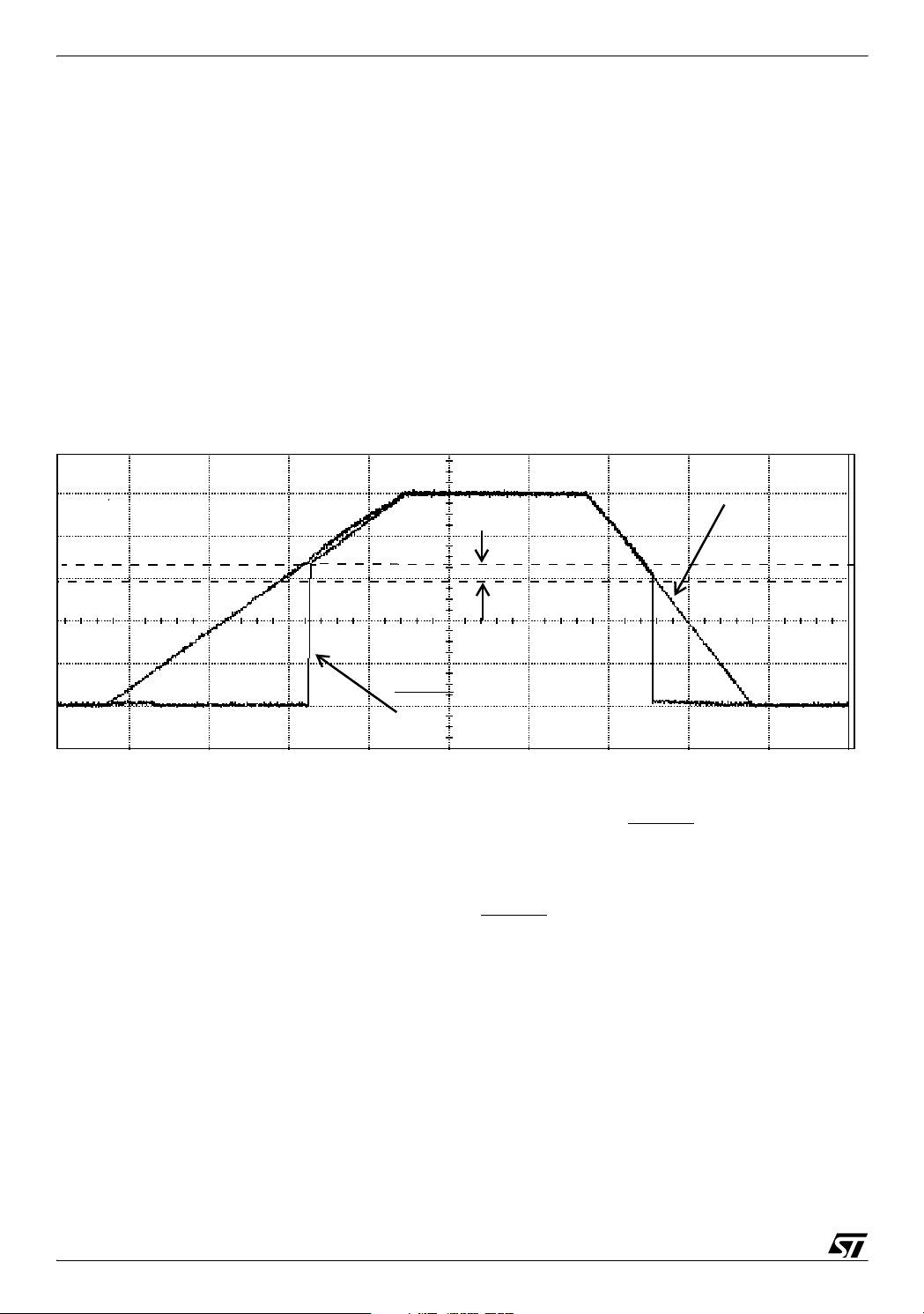
Figure 1. LVD Vs Reset
V
DD
V
IT+(LVD
V
IT-(LVD)
V
Hysteresis
RESET
The voltage threshold can be configured by option byte to be low, medium or high. The LVD
is an optional function which can be selected through option byte and it allows the device to be
used without any External Reset circuitry. During a LVD reset, the RESET
pin is held low, thus
permitting the MCU to reset other devices.
After the device is powered on the supply voltage starts increasing. when the supply voltage
reaches around 1.1V, the internal pull-up on the RESET
ized. After the V
reaches 1.8V, the option bytes are enabled, LVD is enabled by the option
DD
pin is enabled and the core is initial-
bytes (if selected) and the device is in Run mode. The reset will be released at the reset release threshold: high, medium or low depending upon the selection through option bytes.
2/10
2
Page 3

DIFFERENT WAYS TO RESET ST7 MICROCONTROLLER
2 INTERNAL WATCHDOG RESET
The Watchdog timer is used to detect the occurrence of a software fault, usually generated by
external interference or by unforeseen logical conditions, which cause the application program
to abandon its normal sequence. The watchdog circuit generates an MCU reset on expiry of a
programmed time period, unless the counter contents are refreshed.
The hardware WDG selectable through option byte is on immediately after reset. The software
WDG will have to be switched on through software. Both, once set on, can no longer be disabled.
2.1 WATCHDOG TIMER
This is present in all ST7 devices except ST7FLite0. It is a programmable free-running down
counter. The length of the timeout period can be programmed by the user in 64 increments by
varying the counter stored in CR register.
If the watchdog is activated (the WDGA bit is set) and when the 7-bit timer rolls over from 40h
to 3Fh, it initiates a reset cycle pulling low reset pin for typically 30µs.
The application program must regularly refresh the watchdog before its timeout period expires
in order to prevent MCU reset. The WDGCR register must be written at regular intervals and
the value stored in the register must be between FFh and C0h.
2.2 WATCHDOG (LITE TIMER)
This Watchdog is present in ST7FLite0 for instance. The watchdog runs with the Lite Timer.
The normal watchdog timeout period is 2msec (@8MHz F
) after which it generates a
CPU
reset. A watchdog reset can be forced at any time provided that the watchdog is already active.
To prevent a watchdog reset, software must set the WDGD bit before the timeout period has
elapsed.
3/10
Page 4

DIFFERENT WAYS TO RESET ST7 MICROCONTROLLER
3 EXTERNAL RESET
A reset signal originating from an external source is one of the ways in which you can reset the
microcontroller. This signal must have a duration of at least the External reset pulse hold time,
t
h(RSTL)
can enter reset state even in Halt mode.
There are several reset implementation schemes to choose from based on your applicationspecific parameters, such as power supply behaviour. Whatever the solution chosen, the idea
is to keep the RESET
voltage. Therefore you should design your external circuit in such a manner that there is
enough delay to keep the RESET
3.1 RCD Circuit
This concept is the simplest, most cost-effective external reset solution where the supply
waveform is monotonous and the maximum rise time is known. The principle is to let the
RESET
The basic solution is to use an RC delay determined by the rise rate of the supply itself. The
component values must be chosen to create enough delay to keep the RESET
V
stant) corresponding to at least 30% of the total rise time is generally advised.
1)
in order to be recognized. This detection is asynchronous and therefore the MCU
pin at a low logic level until the supply has reached a safe operating
pin below the VIL value.
pin rises with the MCU supply voltage after a delay. The circuit is shown in Figure 2.
pin below the
2)
specification until VDD reaches a safe operating voltage. Normally, a delay (Time Con-
IL
Figure 2. RCD Circuit
D
V
DD
RESET
R
C
This scheme requires a certain delay between a power-down and next power-up, because the
delay generator has to be re initialized. In practice, a pull-down capacitor between RESET
Gnd needs to be discharged. The diode between RESET
charges the capacitor when V
falls. This helps ensure a proper RESET pin input on the sub-
DD
and VDD is helpful, it quickly dis-
and
sequent power-up, should it occur soon after the power down (the delay required is reduced).
The difference in the discharge time of the Capacitor with and without the diode is significant
from Figure 3.
1 For specific t
2 For specific
4/10
h(RSTL)
V
values refer to the datasheet of the particular microcontroller
values refer the to datasheet of the particular microcontroller
IL
Page 5
DIFFERENT WAYS TO RESET ST7 MICROCONTROLLER
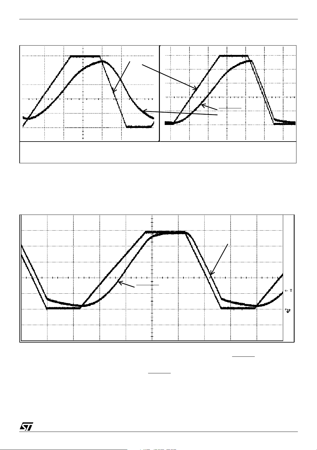
Figure 3. Waveform of Power-on-Reset with RCD Circuit (Without MCU)
V
DD
RESET
Without Diode - Capacitor discharges
very slowly
With Diode - Capacitor discharges
quickly
On ST7 there are internal protection diodes on the pads, which would solve the purpose of this
external diode, thereby you could do away with this diode in your actual implementation with
the MCU. The waveform of Power-on Reset with the External RC Circuit connected to ST7
without the diode is shown in Figure 4.
Figure 4. Waveform of Power-on-Reset with RC Circuit (With MCU)
R=47K, C=10uF
VDD risetime = 1250msec/5V
V
DD
RESET
,
One consideration when choosing the values of the resistor and capacitor is to ensure that resistor’s value does not get too high and interfere with the ability to drive RESET
pin high given
the worst case leakage current of the pin. Higher resistor values in the order of Mega Ohms
could possibly create an input level on the RESET
pin that would be below the VIH specification. The capacitor should not be too large when using MCU’s that have an active internal
reset because this could mask the Internal reset. So, a proper combination of component
values is required. Because of this limitation of selecting higher component values, this solu-
5/10
Page 6

DIFFERENT WAYS TO RESET ST7 MICROCONTROLLER
tion cannot be used for very slow supply voltage rise time. It would suitable when the rise time
is fairly fast.
In all ST7 microcontrollers you have a weak pull-up equivalent resistor whose values differ for
different MCU. This equivalent resistor is sensitive to temperature so while calculating the
component values based on the maximum supply rise time, please remember to take this resistor into account as it would come in parallel with the external resistor. In case your application would be running at very low temperature an internal pull-up resistor at the RESET
pin
would have a minimum value.
This circuit cannot be used when the power supply oscillates during power-down. As the
supply may drop momentarily (oscillate) below the minimum safe level, with the RESET
held high, as a consequence internal logic is not guaranteed any more, and the RESET
pin
pin
cannot be seen at a logic low level to ensure a safe restart.
3.2 Transistor based External Reset circuits
This solution is necessary if the supply voltage rise time is unspecified or it is very slow.
The transistor is closed as long as the supply voltage is below the threshold value, this allows
the pull-down resistor at the reset pin to pull reset low. Once the V
threshold value the transistor is open, keeping the RESET
at VDD, thereby releasing the reset.
rises above this
DD
The transistor is turned on once the voltage from emitter to base drops below a certain value,
usually around 0.6-0.7V.
Figure 5. Transistor based External Reset circuit with potential divider to bias the
transistor.
V
DD
1K
RESET
R1
10K
R2
Resistors, R1 and R2 form a voltage divider which controls the emitter-base voltage. The
threshold is defined by {(R1+R2)/R1}*Vbe
Depending on the threshold required and the emitter-base voltage of the transistor, you would
get the ratio of two resistance, R2/R1. Selecting the resistor values in order to satisfy this ratio
would give the desired threshold.
While making the selection of the pull-down resistance connected at the RESET
certain points to be considered. The RESET
pin in ST7 has a pull-up resistance of minimum
pin there are
20K, when the transistor is off this pull-up resistance and the pull-down resistance at the
6/10
Page 7

DIFFERENT WAYS TO RESET ST7 MICROCONTROLLER
RESET pin connected externally form a voltage divider. Hence, this pull-down resistor should
be selected in such a way ensuring the voltage at the RESET
pin is sufficiently low to reset the
microcontroller. Keeping this in mind the recommended value for this pull-down resistor is 10K
or lower, thus keeping the voltage at the RESET
pin less than (1/3)*Vdd.
Figure 6. Waveform of Power-on-Reset with PNP Reset Circuit (Transistor biased with
Potential divider)
R1= 33K, R2=150K
V
DD
Threshold= 3.3V @Vbe = 0.6V
RESET
When you require more precision in terms of voltage threshold then you can replace resistor
R2 with a Zener diode. In this case the threshold of the circuit would be equal to the breakdown voltage of the Zener diode, V
. Otherwise, the basic operation of this circuit is same as
Z
above circuit.
Figure 7. Transistor based External Reset circuit with Zener diode to bias the transistor
V
DD
1K
RESET
R1
10K
V
Z
7/10
Page 8

DIFFERENT WAYS TO RESET ST7 MICROCONTROLLER
4 RECOMMENDATIONS TO PROVIDE A SAFE RESET
There are a few points which should always be kept in mind to avoid unwanted situations.
They are:
– To avoid the device from entering in ICC mode during a reset, it is mandatory to put an ex-
ternal pull-up of 10K on ICC CLK pin in a noisy environment (only in the case of devices that
do not have ICCSEL).
– The supply voltage should rise monotonously when the device is exiting from reset using In-
ternal LVD, to ensure application starts properly.
– The pull-down resistor at RESET
pin should not be more than 10K for External Reset circuits.
– If the supply voltage is rising in steps please ensure that the first step is at 2V in less than
40msec so that the MCU starts properly.
– It is better to use External Reset circuits when the capacitive power supply is used, since the
supply voltage rises very slowly and is out of range of Internal LVD due to the large capacitance value.
– Please refer the datasheet of the device carefully for certain device specific precautions/ rec-
ommendations.
8/10
Page 9

DIFFERENT WAYS TO RESET ST7 MICROCONTROLLER
5 PROS AND CONS OF DIFFERENT TYPES OF RESET MECHANISM
This section includes the advantages and disadvantages of both External Reset and Internal
LVD. In the section below ‘+’ indicates advantages and ‘-’ indicates disadvantages.
5.1 EXTERNAL RESET CIRCUIT
+ It can be used for very slow rising supply. External RCD circuit is suitable for fairly fast VDD
slopes. Transistor based Reset circuits can be used for very slow VDD slopes
- Extra components required resulting in additional cost and extra space on PCB
- Current consumption (Transistor based External Reset circuits) higher than that of Internal
LVD
5.2 INTERNAL LVD
+ Each MCU has three programmable thresholds
+ No additional cost, as this feature come with the microcontroller
+ No extra components, no extra space on the PCB
- LVD current consumption quite high when compared to External LVD
- VDD slope range is limited
- Supply Voltage should rise monotonously for correct functionality of LVD
- Poor accuracy of reset voltage threshold
5.3 EXTERNAL LVD
+ Could be useful if the application requires a specific threshold (other than LVD threshold)
+ Power consumption much less (6uA for STM809-812)
+ Offers excellent immunity to supply transients
+ A stand alone Reset can monitor a special voltage for a peripheral
+ Several stand alone resets can be put in parallel.
+ Reset threshold more accurate
- One chip can provide only one threshold (Internal LVD has three programmable thresholds)
- Extra space on PCB
- Additional cost, cost: 1 to 10K units: $0.16
9/10
Page 10

DIFFERENT WAYS TO RESET ST7 MICROCONTROLLER
“THE PRESENT NOTE WHICH IS FOR GUIDANCE ONLY AIMS AT PROVIDING CUSTOMERS WITH INFORMATION
REGARDING THEIR PRODUCTS IN ORDER FOR THEM TO SAVE TIME. AS A RESULT, STMICROELECTRONICS
SHALL NOT BE HELD LIABLE FOR ANY DIRECT, INDIRECT OR CONSEQUENTIAL DAMAGES WITH RESPECT TO
ANY CLAIMS ARISING FROM THE CONTENT OF SUCH A NOTE AND/OR THE USE MADE BY CUSTOMERS OF
THE INFORMATION CONTAINED HEREIN IN CONNECTION WITH THEIR PRODUCTS.”
Information furnished is believed to be accurate and reliable. However, STMicroelectronics assumes no responsibility for the consequences
of use of such information nor for any infringement of patents or other rights of third parties which may result from its use. No license is granted
by implication or otherwise under any patent or patent rights of STMicroelectronics. Specifications mentioned in this publication are subject
to change without notice. This publication supersedes and replaces all information previously supplied. STMicroelectronics products are not
authorized for use as critical components in life support devices or systems without express written approval of STMicroelectronics.
The ST logo is a registered trademark of STMicroelectronics.
All other names are the property of their respective owners
© 2005 STMicroelectronics - All rights reserved
STMicroelectronics group of companies
Australia – Belgium - Brazil - Canada - China – Czech Republic - Finland - France - Germany - Hong Kong - India - Israel - Italy - Japan -
Malaysia - Malta - Morocco - Singapore - Spain - Sweden - Switzerland - United Kingdom - United States of America
www.st.com
10/10
 Loading...