

Page 1

AN2014
Application note
How a designer can make the most of STMicroelectronics Serial
EEPROMs
Introduction
Electrically erasable and programmable memory (EEPROM) devices are standard products,
used for the non-volatile storage of parameters and fine-granularity data.
There is no single memory technology (SRAM, DRAM, EEPROM, Flash Memory, EPROM,
ROM) that meets an application’s needs perfectly. Consequently, the designer needs to
know the particular strengths and weaknesses of each technology for optimal use in a given
application. He can then design the application to keep within the specification, for the best
performance, best reliability and lowest failure rates. Lately, this involves understanding at
least the general principles of how the devices, in the given technology, are constructed, and
how they work.
This document has been designed to give precisely this level of background understanding
for one of those technologies: EEPROM, from STMicroelectronics. It describes how
STMicroelectronics’ EEPROM is constructed, how it works, and gives useful guidelines for
achieving high reliability applications under some of the most stringent conditions, such as
those that are experienced in the automotive market.
March 2012 Doc ID 10701 Rev 8 1/69
www.st.com
Page 2

Contents AN2014
Contents
1 EEPROM cell and memory array architecture . . . . . . . . . . . . . . . . . . . . 7
1.1 Floating gate operation within an EEPROM cell . . . . . . . . . . . . . . . . . . . . 7
1.1.1 Reading the value stored in a memory cell . . . . . . . . . . . . . . . . . . . . . . . 9
1.1.2 Writing a new value to the memory cell . . . . . . . . . . . . . . . . . . . . . . . . . 10
1.1.3 Cycling limit of EEPROM cells . . . . . . . . . . . . . . . . . . . . . . . . . . . . . . . . 13
1.2 Electrical architecture of ST serial EEPROM arrays . . . . . . . . . . . . . . . . 14
1.2.1 Memory array architecture . . . . . . . . . . . . . . . . . . . . . . . . . . . . . . . . . . . 14
1.2.2 Decoding architecture . . . . . . . . . . . . . . . . . . . . . . . . . . . . . . . . . . . . . . 15
1.2.3 Intrinsic electrical stress induced by programming . . . . . . . . . . . . . . . . 15
2 Choosing a suitable EEPROM for your application . . . . . . . . . . . . . . . 17
2.1 Choosing a memory type suited to the task to be performed . . . . . . . . . . 17
2.2 Choosing an appropriate memory interface . . . . . . . . . . . . . . . . . . . . . . . 17
2.3 Choosing an appropriate supply voltage and temperature range . . . . . . 18
3 Recommendations to improve EEPROM reliability . . . . . . . . . . . . . . . 19
3.1 Electrostatic discharges (ESD) . . . . . . . . . . . . . . . . . . . . . . . . . . . . . . . . . 19
3.1.1 What is ESD? . . . . . . . . . . . . . . . . . . . . . . . . . . . . . . . . . . . . . . . . . . . . 19
3.1.2 How to prevent ESD? . . . . . . . . . . . . . . . . . . . . . . . . . . . . . . . . . . . . . . 19
3.1.3 ST EEPROM ESD protection . . . . . . . . . . . . . . . . . . . . . . . . . . . . . . . . . 19
3.2 Electrical overstress and latchup . . . . . . . . . . . . . . . . . . . . . . . . . . . . . . . 20
3.2.1 What are EOS and latchup? . . . . . . . . . . . . . . . . . . . . . . . . . . . . . . . . . 20
3.2.2 How to prevent EOS and latchup events . . . . . . . . . . . . . . . . . . . . . . . . 20
3.2.3 ST EEPROM latchup protection . . . . . . . . . . . . . . . . . . . . . . . . . . . . . . 21
3.3 Power supply considerations . . . . . . . . . . . . . . . . . . . . . . . . . . . . . . . . . . 22
3.3.1 Power-up and power-on-reset sequence . . . . . . . . . . . . . . . . . . . . . . . . 22
3.3.2 Stabilized power supply voltage . . . . . . . . . . . . . . . . . . . . . . . . . . . . . . . 23
3.3.3 Absolute maximum ratings . . . . . . . . . . . . . . . . . . . . . . . . . . . . . . . . . . . 23
4 Hardware considerations . . . . . . . . . . . . . . . . . . . . . . . . . . . . . . . . . . . . 24
4.1 I2C family (M24xxx devices) . . . . . . . . . . . . . . . . . . . . . . . . . . . . . . . . . . . 24
4.1.1 Chip enable (E0, E1, E2) . . . . . . . . . . . . . . . . . . . . . . . . . . . . . . . . . . . . 24
4.1.2 Serial data (SDA) . . . . . . . . . . . . . . . . . . . . . . . . . . . . . . . . . . . . . . . . . . 25
4.1.3 Serial clock (SCL) . . . . . . . . . . . . . . . . . . . . . . . . . . . . . . . . . . . . . . . . . 26
2/69 Doc ID 10701 Rev 8
Page 3

AN2014 Contents
4.1.4 Write control (WC) . . . . . . . . . . . . . . . . . . . . . . . . . . . . . . . . . . . . . . . . . 27
4.1.5 Recommended I
2
C EEPROM connections . . . . . . . . . . . . . . . . . . . . . . 29
4.2 SPI family (M95xxx devices) . . . . . . . . . . . . . . . . . . . . . . . . . . . . . . . . . . 30
4.2.1 Chip Select (S) . . . . . . . . . . . . . . . . . . . . . . . . . . . . . . . . . . . . . . . . . . . . 30
4.2.2 Write Protect (W) . . . . . . . . . . . . . . . . . . . . . . . . . . . . . . . . . . . . . . . . . . 30
4.2.3 Serial Data input (D) and Serial Clock (C) . . . . . . . . . . . . . . . . . . . . . . . 31
4.2.4 Hold (HOLD) . . . . . . . . . . . . . . . . . . . . . . . . . . . . . . . . . . . . . . . . . . . . . 31
4.2.5 Serial Data output (Q) . . . . . . . . . . . . . . . . . . . . . . . . . . . . . . . . . . . . . . 32
4.2.6 Recommended SPI EEPROM connections . . . . . . . . . . . . . . . . . . . . . . 33
4.3 MICROWIRE® family (M93Cxxx and M93Sxxx devices) . . . . . . . . . . . . . 35
4.3.1 Chip Select (S) . . . . . . . . . . . . . . . . . . . . . . . . . . . . . . . . . . . . . . . . . . . . 35
4.3.2 Serial Data (D) and Serial Clock (C) . . . . . . . . . . . . . . . . . . . . . . . . . . . 35
4.3.3 Organization Select (ORG) . . . . . . . . . . . . . . . . . . . . . . . . . . . . . . . . . . 36
4.3.4 Serial Data output (Q) . . . . . . . . . . . . . . . . . . . . . . . . . . . . . . . . . . . . . . 36
4.3.5 Don’t use (DU) . . . . . . . . . . . . . . . . . . . . . . . . . . . . . . . . . . . . . . . . . . . . 36
4.3.6 Recommended MICROWIRE EEPROM connections . . . . . . . . . . . . . . 37
4.4 PCB Layout considerations . . . . . . . . . . . . . . . . . . . . . . . . . . . . . . . . . . . 38
4.4.1 Cross coupling . . . . . . . . . . . . . . . . . . . . . . . . . . . . . . . . . . . . . . . . . . . . 38
4.4.2 Noise and disturbances on power supply lines . . . . . . . . . . . . . . . . . . . 38
5 Software considerations . . . . . . . . . . . . . . . . . . . . . . . . . . . . . . . . . . . . . 39
5.1 EEPROM electrical parameters . . . . . . . . . . . . . . . . . . . . . . . . . . . . . . . . 39
5.2 Optimal Write control . . . . . . . . . . . . . . . . . . . . . . . . . . . . . . . . . . . . . . . . 39
5.2.1 Page mode . . . . . . . . . . . . . . . . . . . . . . . . . . . . . . . . . . . . . . . . . . . . . . . 40
5.2.2 Data polling . . . . . . . . . . . . . . . . . . . . . . . . . . . . . . . . . . . . . . . . . . . . . . 40
5.3 Write protection . . . . . . . . . . . . . . . . . . . . . . . . . . . . . . . . . . . . . . . . . . . . 44
5.3.1 Software write protection . . . . . . . . . . . . . . . . . . . . . . . . . . . . . . . . . . . . 44
5.3.2 Hardware write protection . . . . . . . . . . . . . . . . . . . . . . . . . . . . . . . . . . . 44
5.4 Data integrity . . . . . . . . . . . . . . . . . . . . . . . . . . . . . . . . . . . . . . . . . . . . . . 45
5.4.1 The checksum . . . . . . . . . . . . . . . . . . . . . . . . . . . . . . . . . . . . . . . . . . . . 45
5.4.2 Data redundancy . . . . . . . . . . . . . . . . . . . . . . . . . . . . . . . . . . . . . . . . . . 46
5.4.3 Checksum and data redundancy . . . . . . . . . . . . . . . . . . . . . . . . . . . . . . 47
5.4.4 Extra redundancy . . . . . . . . . . . . . . . . . . . . . . . . . . . . . . . . . . . . . . . . . . 47
5.5 Cycling endurance and data retention . . . . . . . . . . . . . . . . . . . . . . . . . . . 48
5.5.1 Values specified in device datasheets . . . . . . . . . . . . . . . . . . . . . . . . . . 48
5.5.2 Optimal cycling with ECC (error correction code) . . . . . . . . . . . . . . . . . 48
Doc ID 10701 Rev 8 3/69
Page 4

Contents AN2014
5.5.3 Cycling and temperature dependence . . . . . . . . . . . . . . . . . . . . . . . . . . 50
5.5.4 Defining the application cycling strategy . . . . . . . . . . . . . . . . . . . . . . . . 51
5.5.5 Overall number of write cycles . . . . . . . . . . . . . . . . . . . . . . . . . . . . . . . . 52
6 Power supply loss and application reset . . . . . . . . . . . . . . . . . . . . . . . 53
6.1 Application reset . . . . . . . . . . . . . . . . . . . . . . . . . . . . . . . . . . . . . . . . . . . . 53
6.1.1 I2C family . . . . . . . . . . . . . . . . . . . . . . . . . . . . . . . . . . . . . . . . . . . . . . . . 53
6.1.2 SPI family . . . . . . . . . . . . . . . . . . . . . . . . . . . . . . . . . . . . . . . . . . . . . . . . 55
6.1.3 MICROWIRE family . . . . . . . . . . . . . . . . . . . . . . . . . . . . . . . . . . . . . . . . 56
6.2 Power supply loss . . . . . . . . . . . . . . . . . . . . . . . . . . . . . . . . . . . . . . . . . . . 57
6.2.1 Hardware recommendations . . . . . . . . . . . . . . . . . . . . . . . . . . . . . . . . . 57
6.2.2 Supply voltage energy tank capacitor . . . . . . . . . . . . . . . . . . . . . . . . . . 57
6.2.3 Interruption of an EEPROM request . . . . . . . . . . . . . . . . . . . . . . . . . . . 59
6.3 Robust software and default operating mode . . . . . . . . . . . . . . . . . . . . . . 62
7 Operating conditions . . . . . . . . . . . . . . . . . . . . . . . . . . . . . . . . . . . . . . . 63
7.1 Temperature . . . . . . . . . . . . . . . . . . . . . . . . . . . . . . . . . . . . . . . . . . . . . . . 63
7.2 Humidity and chemical vapors . . . . . . . . . . . . . . . . . . . . . . . . . . . . . . . . . 63
7.3 Mechanical stress . . . . . . . . . . . . . . . . . . . . . . . . . . . . . . . . . . . . . . . . . . . 63
8 Conclusions . . . . . . . . . . . . . . . . . . . . . . . . . . . . . . . . . . . . . . . . . . . . . . . 64
9 Reference . . . . . . . . . . . . . . . . . . . . . . . . . . . . . . . . . . . . . . . . . . . . . . . . . 65
10 Revision history . . . . . . . . . . . . . . . . . . . . . . . . . . . . . . . . . . . . . . . . . . . 66
4/69 Doc ID 10701 Rev 8
Page 5

AN2014 List of tables
List of tables
Table 1. Three serial bus protocols . . . . . . . . . . . . . . . . . . . . . . . . . . . . . . . . . . . . . . . . . . . . . . . . . 18
Table 2. ESD generation . . . . . . . . . . . . . . . . . . . . . . . . . . . . . . . . . . . . . . . . . . . . . . . . . . . . . . . . . 19
Table 3. Typical POR threshold values . . . . . . . . . . . . . . . . . . . . . . . . . . . . . . . . . . . . . . . . . . . . . . 22
Table 4. Connecting the Ei inputs of I²C products . . . . . . . . . . . . . . . . . . . . . . . . . . . . . . . . . . . . . . 24
Table 5. Calculation rules for pull-up resistor on SDA
Table 6. Connecting WC inputs in I2C products . . . . . . . . . . . . . . . . . . . . . . . . . . . . . . . . . . . . . . . . 28
Table 7. Calculation for external pull-up and pull-down resistors in SPI products . . . . . . . . . . . . . . 34
Table 8. Calculating external pull-up and pull-down resistors in MICROWIRE products . . . . . . . . . 37
Table 9. Column and page address bits according to page length. . . . . . . . . . . . . . . . . . . . . . . . . . 46
Table 10. Application cycling profile evaluation . . . . . . . . . . . . . . . . . . . . . . . . . . . . . . . . . . . . . . . . . 51
Table 11. Document revision history . . . . . . . . . . . . . . . . . . . . . . . . . . . . . . . . . . . . . . . . . . . . . . . . . 66
(1) . . . . . . . . . . . . . . . . . . . . . . . . . . . . . . . . . . . . . . . . . . . 25
Doc ID 10701 Rev 8 5/69
Page 6

List of figures AN2014
List of figures
Figure 1. Structure of an EEPROM floating gate transistor, and circuit symbol. . . . . . . . . . . . . . . . . . 7
Figure 2. MOSFET-like operation . . . . . . . . . . . . . . . . . . . . . . . . . . . . . . . . . . . . . . . . . . . . . . . . . . . . 7
Figure 3. Floating gate reservoir full of electrons (Erased state) . . . . . . . . . . . . . . . . . . . . . . . . . . . . . 8
Figure 4. Floating gate reservoir empty of electrons (Written state) . . . . . . . . . . . . . . . . . . . . . . . . . . 8
Figure 5. Using the voltage on the control gate to determine the charge on the floating gate. . . . . . . 9
Figure 6. During erase, electrons go through the tunnel oxide into the floating gate. . . . . . . . . . . . . 10
Figure 7. During write, electrons go through the tunnel oxide out of the floating gate . . . . . . . . . . . . 11
Figure 8. VPP signal applied to EEPROM cells
(HiV is the output of the charge pump) . . . . . . . . . . . . . . . . . . . . . . . . . . . . . . . . . . . . . . . . 12
Figure 9. Accumulation of negative or positive charges in the tunnel oxide . . . . . . . . . . . . . . . . . . . 13
Figure 10. Architecture of the memory array (showing the grouping in bytes). . . . . . . . . . . . . . . . . . . 14
Figure 11. Decoding block diagram . . . . . . . . . . . . . . . . . . . . . . . . . . . . . . . . . . . . . . . . . . . . . . . . . . . 15
Figure 12. Latchup mechanism and protection . . . . . . . . . . . . . . . . . . . . . . . . . . . . . . . . . . . . . . . . . . 21
Figure 13. Latchup test conditions . . . . . . . . . . . . . . . . . . . . . . . . . . . . . . . . . . . . . . . . . . . . . . . . . . . . 21
Figure 14. Power-up . . . . . . . . . . . . . . . . . . . . . . . . . . . . . . . . . . . . . . . . . . . . . . . . . . . . . . . . . . . . . . 22
Figure 15. Local EEPROM supply filtering. . . . . . . . . . . . . . . . . . . . . . . . . . . . . . . . . . . . . . . . . . . . . . 23
Figure 16. Chip Enable inputs E0, E1, E2 . . . . . . . . . . . . . . . . . . . . . . . . . . . . . . . . . . . . . . . . . . . . . . 24
Figure 17. Serial Data input/output SDA . . . . . . . . . . . . . . . . . . . . . . . . . . . . . . . . . . . . . . . . . . . . . . . 25
Figure 18. SDA bus conflict with push-pull buffers (NOT RECOMMENDED) . . . . . . . . . . . . . . . . . . . 26
Figure 19. Serial Clock input SCL . . . . . . . . . . . . . . . . . . . . . . . . . . . . . . . . . . . . . . . . . . . . . . . . . . . . 27
Figure 20. Write Control input (WC). . . . . . . . . . . . . . . . . . . . . . . . . . . . . . . . . . . . . . . . . . . . . . . . . . . 27
Figure 21. Recommended I²C connections – safe design . . . . . . . . . . . . . . . . . . . . . . . . . . . . . . . . . . 29
Figure 22. Recommended I²C connections – robust design . . . . . . . . . . . . . . . . . . . . . . . . . . . . . . . . 29
Figure 23. Chip Select, Clock, Data, Hold input pins . . . . . . . . . . . . . . . . . . . . . . . . . . . . . . . . . . . . . . 30
Figure 24. Write Protect input W . . . . . . . . . . . . . . . . . . . . . . . . . . . . . . . . . . . . . . . . . . . . . . . . . . . . . 31
Figure 25. Output pin tri-state buffer . . . . . . . . . . . . . . . . . . . . . . . . . . . . . . . . . . . . . . . . . . . . . . . . . . 32
Figure 26. Recommended SPI connections - safe design . . . . . . . . . . . . . . . . . . . . . . . . . . . . . . . . . . 33
Figure 27. Recommended SPI connections - robust design . . . . . . . . . . . . . . . . . . . . . . . . . . . . . . . . 33
Figure 28. Chip Select, Clock, Data input pins . . . . . . . . . . . . . . . . . . . . . . . . . . . . . . . . . . . . . . . . . . 35
Figure 29. Organization input ORG . . . . . . . . . . . . . . . . . . . . . . . . . . . . . . . . . . . . . . . . . . . . . . . . . . . 36
Figure 30. Recommended MICROWIRE connections - safe design . . . . . . . . . . . . . . . . . . . . . . . . . . 37
Figure 31. Recommended MICROWIRE connections - robust design . . . . . . . . . . . . . . . . . . . . . . . . 37
Figure 32. PCB decoupling . . . . . . . . . . . . . . . . . . . . . . . . . . . . . . . . . . . . . . . . . . . . . . . . . . . . . . . . . 38
Figure 33. I
Figure 34. SPI data polling algorithm . . . . . . . . . . . . . . . . . . . . . . . . . . . . . . . . . . . . . . . . . . . . . . . . . . 42
Figure 35. MICROWIRE data polling algorithm . . . . . . . . . . . . . . . . . . . . . . . . . . . . . . . . . . . . . . . . . . 43
Figure 36. .Recommended use of the WC pin in I²C products . . . . . . . . . . . . . . . . . . . . . . . . . . . . . . 45
Figure 37. Recommended use of the W pin in SPI products . . . . . . . . . . . . . . . . . . . . . . . . . . . . . . . . 45
Figure 38. Example of how to duplicate data safely . . . . . . . . . . . . . . . . . . . . . . . . . . . . . . . . . . . . . . 46
Figure 39. Write cycling versus temperature . . . . . . . . . . . . . . . . . . . . . . . . . . . . . . . . . . . . . . . . . . . . 50
Figure 40. I
Figure 41. SPI bus enters the high impedance state (Master reset) . . . . . . . . . . . . . . . . . . . . . . . . . . 55
Figure 42. MICROWIRE bus enters the high impedance state (Master reset) . . . . . . . . . . . . . . . . . . 56
Figure 43. EEPROM power backup capacitor . . . . . . . . . . . . . . . . . . . . . . . . . . . . . . . . . . . . . . . . . . . 58
Figure 44. Emergency sequence I
Figure 45. Emergency sequence SPI products . . . . . . . . . . . . . . . . . . . . . . . . . . . . . . . . . . . . . . . . . . 60
Figure 46. Emergency sequence MICROWIRE products . . . . . . . . . . . . . . . . . . . . . . . . . . . . . . . . . . 61
2
C data polling algorithm . . . . . . . . . . . . . . . . . . . . . . . . . . . . . . . . . . . . . . . . . . . . . . . . . . 41
2
C bus enters the high impedance state (Master reset) . . . . . . . . . . . . . . . . . . . . . . . . . . 54
2
C products . . . . . . . . . . . . . . . . . . . . . . . . . . . . . . . . . . . . . . . . . . 59
6/69 Doc ID 10701 Rev 8
Page 7

AN2014 EEPROM cell and memory array architecture
AI10227
Tunnel Oxide
Control Gate
Floating Gate
Source
Drain
Gate Oxide
Oxide
Channel Region
Drain
Source
Control Gate
Floating Gate
!)B
6
G
)
D
6
!
$RAIN
3OURCE
6
G
)
D
1 EEPROM cell and memory array architecture
1.1 Floating gate operation within an EEPROM cell
From the user’s point of view, this EEPROM device is a circuit for storing digital information.
To interface with the EEEPROM device a set of standard instructions are used. Behind this
simple interface, however, there are a number of sensitive analog and physical processes.
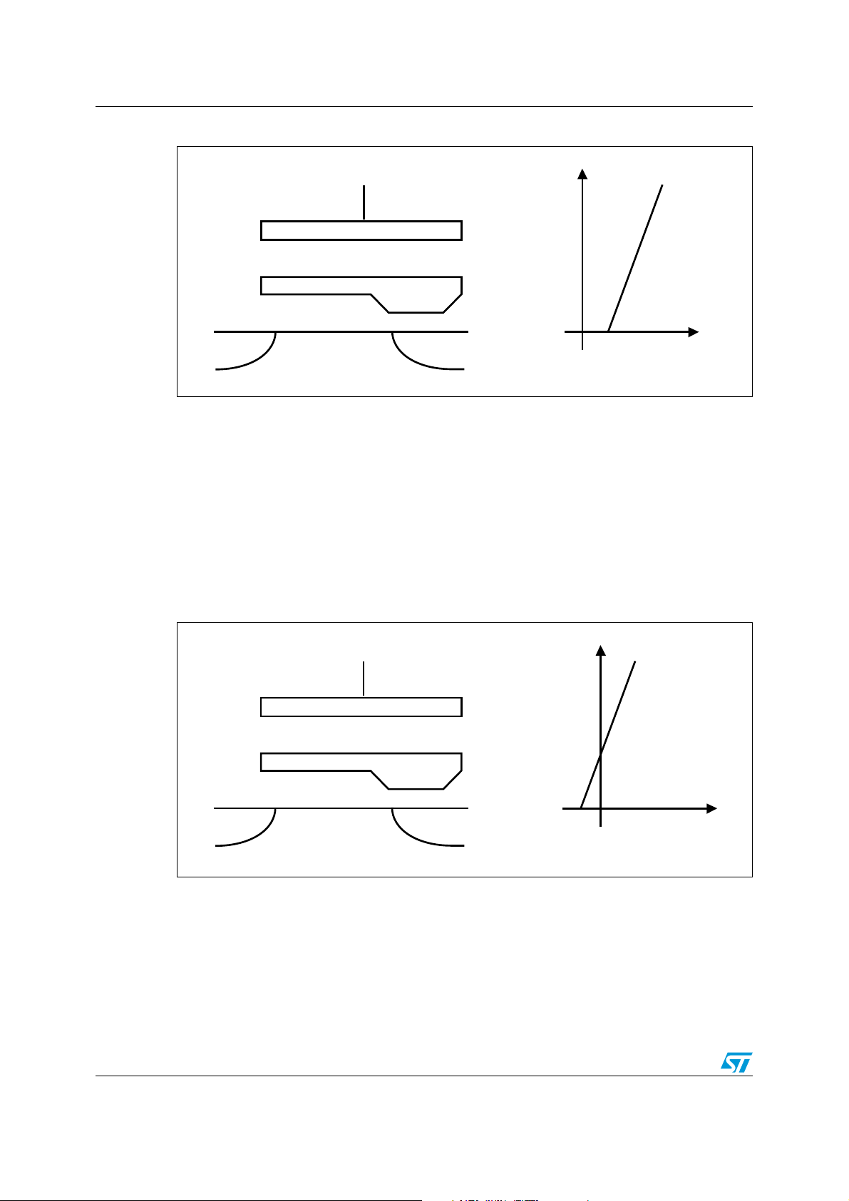
Figure 1. Structure of an EEPROM floating gate transistor, and circuit symbol
Figure 1. shows the key component of a single EEPROM cell, the floating gate transistor
(also known as a FLOTOX transistor). Figure 2. shows how it can be considered to be just
like any other type of MOSFET device. As the voltage, V
electrode, so the current flowing through the drain, I
, is increased on the Control Gate
g
, increases in proportion. For the
d
present, we can assume that this is a fairly linear relationship.
Figure 2. MOSFET-like operation
Figure 3 shows what happens if the Floating Gate can be made more negatively charged,
by filling it with extra electrons. This is used for the Erased state of the EEPROM cell.
Figure 4 shows what happens if the Floating Gate can be made less negatively charged, by
emptying it some of its normal electrons. This is used for the Written state of the EEPROM
cell.
Doc ID 10701 Rev 8 7/69
Page 8
EEPROM cell and memory array architecture AN2014
AI10228
Tunnel Oxide
Control Gate
- - - - - - - - - - - - - - - -
Source
Drain
Gate Oxide
Oxide
V
g
V
g
I
d
- - - - - -
V
th.erase
Channel Region
AI10229
Tunnel Oxide
Control Gate
+ + + + + + + + + + + + +
Source
Drain
Gate Oxide
Oxide
V
g
V
g
I
d
+ + + + +
V
th.write
Channel Region
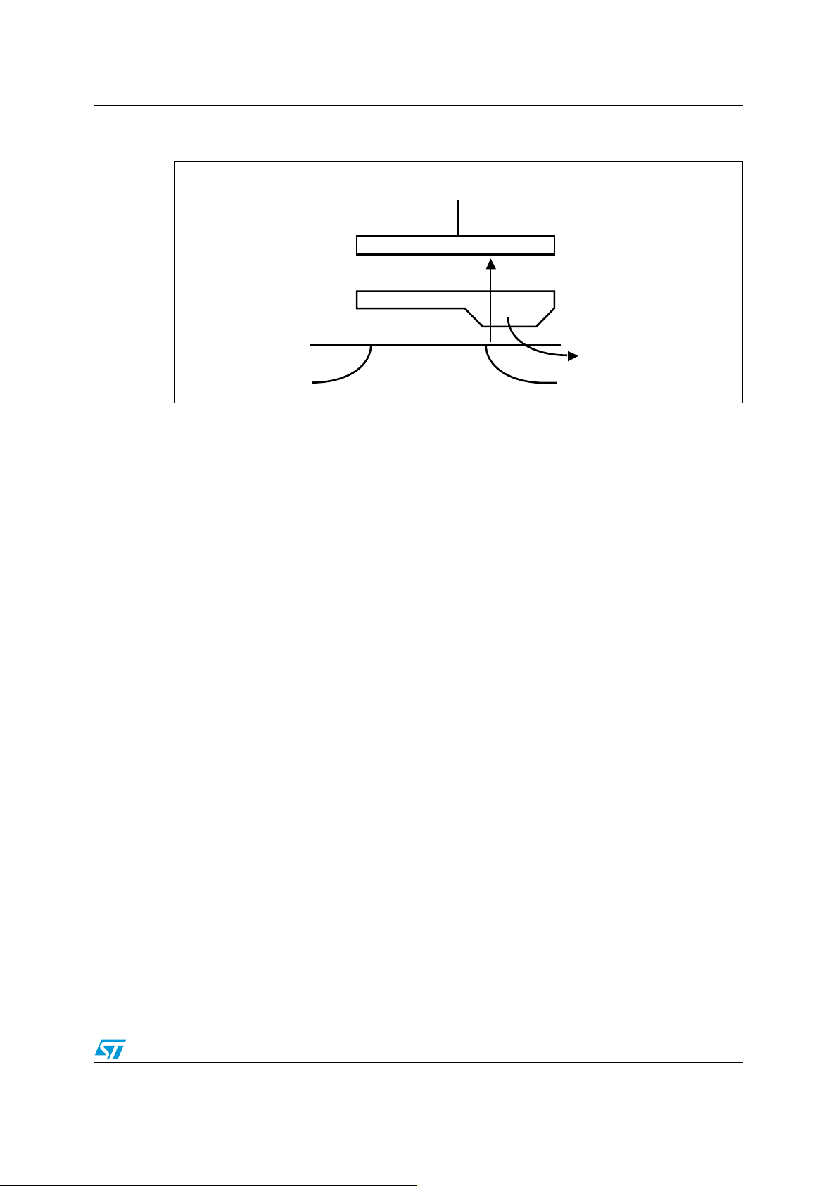
Figure 3. Floating gate reservoir full of electrons (Erased state)
1. Control Gate threshold value (V
= f(Vg) characteristic shows Id=0 for Vg<V
2. I
d
th.erase
) is positive.
th.erase
.
The effect, as viewed from the channel region of the transistor, is that the Control Gate
voltage, V
, is offset by an extra negative or positive amount. Viewed from the outside,
g
black-box electrical behavior of the device, the charge on the Floating Gate has the effect of
moving the threshold MOSFET voltage, V
, at which the linear conduction region begins. In
th
other words, a FLOTOX transistor is a MOS transistor with a variable Control Gate threshold
value, V
.
th
The Floating Gate acts as the storage element, and, being completely surrounded by
insulating oxide, as shown in Figure 1, keeps its charge even when there is no power supply.
Figure 4. Floating gate reservoir empty of electrons (Written state)
1. Control Gate threshold value (V
=f(Vg) characteristic shows Id=0 for Vg<V
2. I
d
8/69 Doc ID 10701 Rev 8
th.write
) is negative
th.write
.
Page 9

AN2014 EEPROM cell and memory array architecture
AI10234
V
g
I
d
V
g.ref
I
d.ref
I
1.1.1 Reading the value stored in a memory cell
Figure 5 puts the three curves together, by way of comparison. It shows that for a given
Control Gate voltage, V
higher or lower than that of the neutral device, depending on whether the reservoir of
electrons on the Floating Gate has been filled up, or emptied. This, then, is the basis of how
the memory cell can be read.
Figure 5. Using the voltage on the control gate to determine the charge on the
floating gate
, the current that flows through the drain, Id, will be detectably
g
1. A written cell draws a current IµA (where IµA > I
); an erased cell does not draw any current (0µA).
d.ref
In most of ST EEPROM products, a predetermined biasing condition on the Control Gate
and the drain makes it possible to compare the current absorbed by the FLOTOX transistor
with a reference. Basically, with the predetermined biasing condition an erased FLOTOX cell
is not able to sink as much current as the reference (ideally the transistor is off). On the
other hand, a written FLOTOX cell sinks a current that is superior to the reference (the
transistor is on). By comparing to a reference current, the device is able to retrieve the
stored information as a digital signal on the output pins of the memory device.
Doc ID 10701 Rev 8 9/69
Page 10

EEPROM cell and memory array architecture AN2014
AI10232
Vg=+18V
Vd=0V
Electric Field
Tunneling Electrons
Control Gate
Source
Drain
Gate Oxide
Oxide
Channel Region
Floating Gate
e
-
1.1.2 Writing a new value to the memory cell
The next question, of course, is how the charge can be changed on the Floating Gate, given
that it is so well insulated by oxide, and keeps its charge even when there is no power
supply. The answer is that the Tunnel Oxide, shown in Figure 1, is very thin, and can be
used to transfer charge, when much higher voltages are applied than those normally used
during Read operations.
Filling the Floating Gate reservoir with negative charges (electrons) is called erase. After
erase, the FLOTOX transistor is in the Erased State (see Figure 3). Pulling out negative
charges from the Floating Gate is called Program. After Program, the FLOTOX transistor is
in the Written State (see Figure 4). One state is used to represent logic-0, and the other
logic-1, but the exact choice is manufacturer and product-type dependent).
Both operations use the Fowler-Nordheim tunneling effect. For this, a high electric field
(1 million V/mm, or more) is needed to make electrons pass through the thin Tunnel Oxide.
For a Tunnel Oxide thickness of 100Å, the high voltage needs to be at least 10V. In fact,
higher voltages, in the range 15 to 18V, are normally used, to reduce the time taken for the
operation. Voltages higher than this cannot be used, since they would damage the thin
Tunnel Oxide.
For erase, the cell Control Gate is made positive, and the source-drain region is grounded
(as shown in Figure 6). The electric field makes electrons move from the substrate towards
the Floating Gate, thereby filling the reservoir, and increasing the characteristic threshold
voltage of the transistor (as shown in Figure 3).
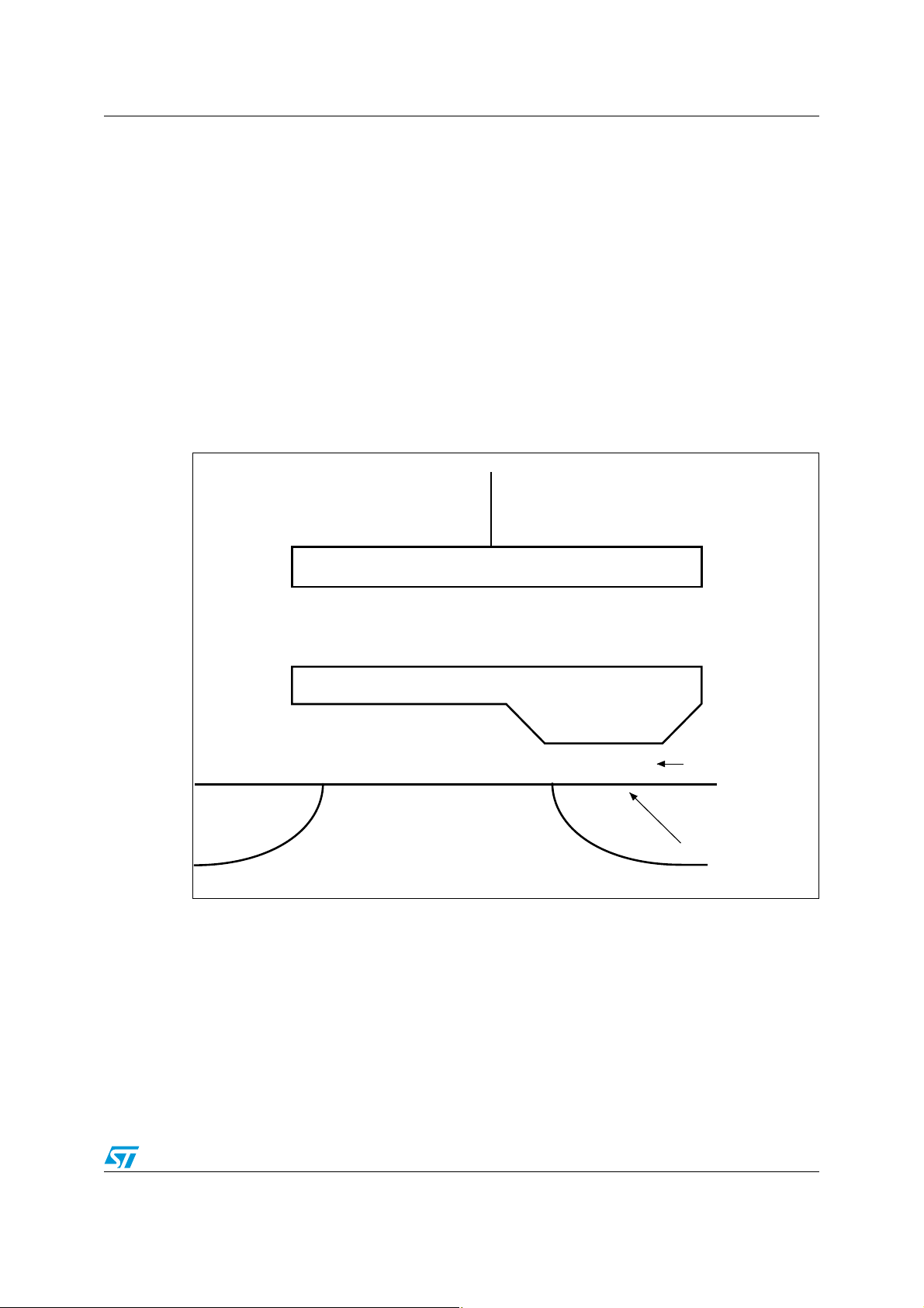
Figure 6. During erase, electrons go through the tunnel oxide into the floating gate
1. Characteristic threshold Vth increases and becomes positive as shown in Figure 3
For write, the Control Gate is grounded and the source-drain region is made positive (as
shown in Figure 7). The electric field is the opposite of that for erase, and so electrons move
out from the Floating Gate, thereby emptying the reservoir, and decreasing the
characteristic threshold voltage of the transistor (as shown in Figure 4).
10/69 Doc ID 10701 Rev 8
Page 11
AN2014 EEPROM cell and memory array architecture
AI10233
Vg=0V
Vd=+18V
Electric Field
Tunneling Electrons
Control Gate
Source
Drain
Gate Oxide
Oxide
Channel Region
Floating Gate
e
-
Figure 7. During write, electrons go through the tunnel oxide out of the floating
gate
1. Characteristic threshold decreases and becomes negative as shown in Figure 4
Typically EEPROM erase/write cycles require a high voltage of about 15 to 18V for
approximately 5ms. As EEPROM devices use a single supply voltage, the high voltage must
be generated and managed internally. A set of analog circuits is available to generate and
control the high voltage from the single external power supply:
● voltage and current references to control oscillators and timings
● a regulated charge pump that generates a stable 15 to 18V voltage, HiV, from the
single external power supply
● a ramp generator that, from the stable HiV voltage, makes the specific waveform
(shown in Figure 8) that is to be applied to the cells
V
is the high voltage that is directly applied to the FLOTOX cell, as described earlier. The
PP
precise shape of the V
voltage waveform is critical, and has a direct effect on the reliability
PP
and endurance of the memory cells. The slope, plate time and maximum level are
parameters that are very carefully controlled.
Writing new data in an EEPROM array triggers an auto-erase of all the addressed bytes,
resets them all to the Erased state, and then selectively programs those bits that should be
set to the Written state.
Doc ID 10701 Rev 8 11/69
Page 12
EEPROM cell and memory array architecture AN2014
AI10235
V
PP
5ms
t(ms)
HiV
18V
Auto-Erase
Program
Write Cycle = Auto-Erase + Program
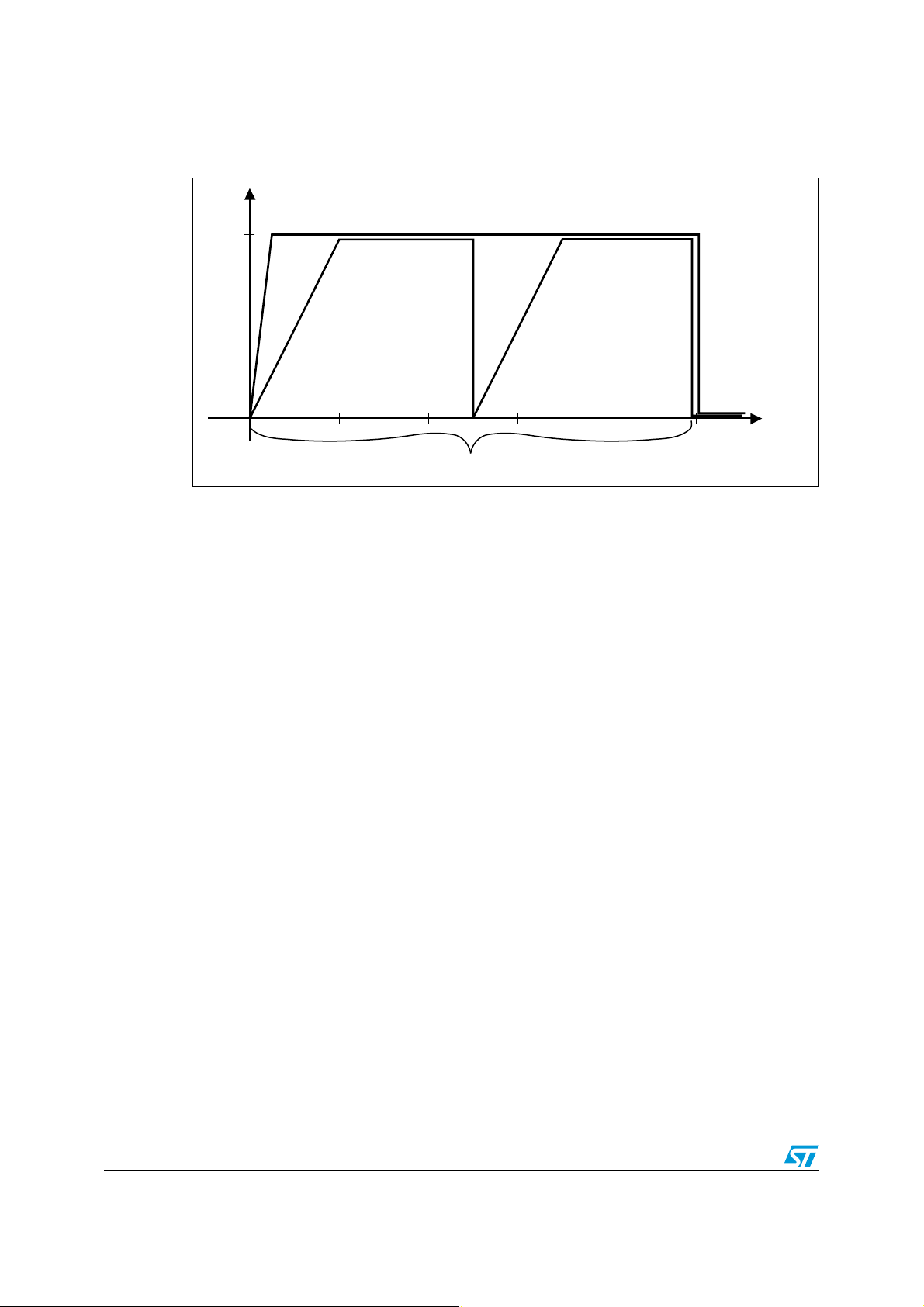
Figure 8. VPP signal applied to EEPROM cells
(HiV is the output of the charge pump)
To summarize: Binary information is coded by means of a FLOTOX transistor. The Floating
Gate is a reservoir filled with negative electric charges that modify its electrical
characteristics. The electric charges can be made to migrate into or out of the reservoir by
applying a high voltage to a thin Tunnel Oxide. The binary information is read by comparing
the cell (FLOTOX transistor) current to a reference.
12/69 Doc ID 10701 Rev 8
Page 13
AN2014 EEPROM cell and memory array architecture
AI10251
Control Gate
Source
Horizontal electric barrier
disturbing erase and write
Oxide
- - + - - -
Channel Region
+
+
Vertical electric path
leading to leakage
Gate Oxide
Floating Gate
1.1.3 Cycling limit of EEPROM cells
When a cell is cycled (repeatedly erased and programmed) two common phenomena occur
and are amplified during the memory cell lifetime. When tunneling, negative charges can
either be trapped in some imperfection of the oxide or damage the Tunnel Oxide:
1. Charge trapping
The accumulation of negative charges in the thin Tunnel Oxide creates an electric
barrier in the Tunnel Oxide. The high voltage needed for the tunneling effect becomes
even higher: programming high voltages are no more able to move enough charges to
program the cell properly. The Erased and Written states become undifferentiated.
2. Stress on oxide
When the Tunnel Oxide deteriorates, a positive charge path may appear, that facilitates
undesirable leakage through the Tunnel Oxide. The Floating Gate is no more 100%
insulated, and loses its charges, and so the data retention time drops drastically.
Figure 9. Accumulation of negative or positive charges in the tunnel oxide
Charge trapping and oxide damage are accelerated at high temperatures. They are directly
involved in cell cycling and endurance limitations.
Permanent digital information storage has to cope with physical phenomena and analog
nonlinear behaviors that have natural limits and are sensitive to wear-out and improper use
conditions.
Doc ID 10701 Rev 8 13/69
Page 14

EEPROM cell and memory array architecture AN2014
Cg-Line 0
8 Bit-Line Latches
Cg line
Bit line
Bit line
Bit line
8 Select
transistors
8 FLOTOX
transistors
Row-
Line 0
b07 b06 b00
Cg-Line i
8 Bit-Line Latches
bi7 bi6 bi0
Control
Gate
transistor
Row-
Line n
AI10224b
Column 0 Column i
Byte
Select
transistor
FLOTOX
transistor
Memory Cell
1.2 Electrical architecture of ST serial EEPROM arrays
In the previous section, the EEPROM functionality was considered at the single bit level.
We will now zoom out of the memory cell to the full EEPROM array, in order to give an
overview of the architecture of an EEPROM device.
1.2.1 Memory array architecture
An EEPROM device is made of an array of memory cells whose organization allows byte
granularity, the automatic erasing of the addressed bytes (Erased state), and the
programming of only those bits that are to be changed to ‘1’ (Written state). The array (as
shown in Figure 10) is organized as follows:
● Each memory cell consists of one Select transistor in series with a FLOTOX transistor
and each byte is made up of eight memory cells and a Control Gate transistor with a
drain that is common to the control gates of all eight FLOTOX transistors.
● Rows (in the horizontal direction) are made up of 16 bytes (or more, depending on the
memory size (the number of bytes within each row being a function of the array size).
For each row, all Select transistors and all Control Gate transistors are connected to the
Row line.
● Columns are grouped by eight bit-lines and one Cg-line. This is then repeated as many
times as the number of bytes in a row.
● A bit-line is common to all the drains of the Select transistors of each memory cell in the
column. A Cg-line is common to all the sources of the Control Gate transistors of the
column.
Figure 10. Architecture of the memory array (showing the grouping in bytes)
14/69 Doc ID 10701 Rev 8
Page 15

AN2014 EEPROM cell and memory array architecture
AI10225
Address Shift Register
Column
Decoder
Bit-line and Cg-line Latches: RAM Buffer
Row
Decoder
Array
Cg-lines and Bit-lines
Row-lines
Read/Write Analog
Voltages
Serial Input
MSB Address Bits LSB Address Bits
1.2.2 Decoding architecture
To address a single byte in a full array, decoding circuits are necessary. One logical address
is associated with one byte location. The address bits are inserted serially into a Shift
Register. Then, with parallel output, the decoding structures receive all of the bits at the
same time, to perform the decoding and addressing. The row decoder decodes and brings
correct biasing to a single row line. As one or more bytes of the same row can be
programmed at the same time, the column decoder decodes one or more column(s), and a
RAM buffer memorizes the data to write, and enables the right path for Cg-line and Bit-line
biasing.
Figure 11. Decoding block diagram
1.2.3 Intrinsic electrical stress induced by programming
Whatever kind of data must be programmed and whether the request is made by byte or
page, all high-voltage circuits are stressed by HiV (a high voltage ranging between 15 and
18V). In particular, the internal nodes of the charge pump can see voltages equal to
HiV + V
regulation, decoding, latches) are submitted to higher stress than active low voltage
transistors. The overall time during which the high voltage circuits are active is relatively
short compared to the product lifetime (10ms x 1Mcycles = 10000 seconds => less than 3
hours).
A standard ST EEPROM device has a few hundred high voltage transistors, for low memory
density products (1Kbit). This number can rise to a few thousand for high memory density
products (1Mbit).
Consider, by way of example, the stress induced on the array elements when programming
one single byte in a 1Kbit EEPROM, organized as 128 x8 bit. The memory array is
composed of 8 pages (or rows) of 16 bytes (or columns).
(that is as much as 23 V). All circuits that receive and carry HiV (ramp generator,
CC
Doc ID 10701 Rev 8 15/69
Page 16

EEPROM cell and memory array architecture AN2014
Erase cycle: the complete row (page) that contains the addressed byte receives the VPP
signal, on the selected Row-line, as does the complete column, on the selected Cg-line:
● Control Gates of all the Select transistors in the given row: 1 row x 16 bytes x 8 bits
=128
● Control Gates of all the Control Gate transistors in the given row: 1 row x 16 bytes = 16
● Drains of all the Control Gate transistors that are connected to the given Cg-line: 1
column x 8 rows = 8
The Bit-lines of the addressed bytes are floating.
Write cycle: the complete row (page) that contains the addressed byte receives the V
PP
signal, on the selected Row-line:
● Control Gates of all the Select transistors in the given row: 1 row x 16 bytes x 8 bits
=128
● Control Gates of all the Control Gate transistors in the given row: 1 row x 16 bytes = 16
● The Cg-line of the addressed byte is held at ground voltage
● The Bit-lines are left floating or receive V
case is when FFh is to be written, and all Bit-lines receive the V
● Drains of all the Select transistors sharing the same 8 Bit-lines: 1 column x 8 rows x 8
depending on data to be written. The worst
PP
PP
signal
bits = 64
This example shows how one single byte, being erased or programmed, incurs a lot of High
Voltage stress on elements that are on the same row, column and bit-line as the one
addressed. For a 1Kbit EEPROM, programming one single byte to FFh induces stress on
128 Select transistors and 24 Control Gate transistors during auto-erase, and 192 Select
transistors and 16 Control Gate transistors during the write cycle, even though only 17
transistors (8 Select transistors, 8 FLOTOX transistors, 1 MOS transistor) were really being
addressed for the data change.
The bigger the memory array, the larger the number of additional transistors that are
involved. This is why when high cycling performance is required, it is recommended to
gather cycled data in contiguous blocks and use the write page mode as much as possible.
16/69 Doc ID 10701 Rev 8
Page 17

AN2014 Choosing a suitable EEPROM for your application
2 Choosing a suitable EEPROM for your application
ST "Automotive Grade" EEPROM products are made to meet automotive’s stringent
requirements. They are produced by a longstanding process and benefit from being tested
continuously for quality as well as specific test strategies like Statistical Bin Limits,
Parametric Average Testing and qualification following the AEC Q100, specific product
buffer stocks, etc.
Nevertheless, the reliability on EEPROM products are also closely linked to the way they are
designed in Applications.The aim of this part of the document is to provide our automotive
customers with a set of practical recommendations for achieving immediate improvements
in application reliability and robustness.
In the case of automotive applications, ST strongly recommends the use of products that
are classified as automotive grade. These devices are designed to satisfy the most stringent
requirements of automotive, sensitive and safety applications. "Grade 3" and Automotive
Grade EEPROMs are tested with STMicroelectronics’ High Reliability Certified Flow
(described in Quality Note, QNEE9801) insuring a very high level of quality.
2.1 Choosing a memory type suited to the task to be performed
EEPROM devices are particularly suited to the tasks of code traceability and parameter
storage. The Serial protocol offers the best compromise of performance versus cost where
the access time is not critical.
2.2 Choosing an appropriate memory interface
ST is specialized in Serial Access EEPROMs, which are based on three main protocols: I²C,
SPI and MICROWIRE (see Ta bl e 1 ).
Fundamental requirements such as noise immunity, ESD, latchup and cycling Endurance
are basic features of each ST Serial EEPROM device (independent from the protocol used).
The choice of the most appropriate Serial EEPROM depends mainly on the hardware
resources of the master and on the architecture built around it. See the following:
● The I
● The SPI bus and MICROWIRE bus are 4-wire protocols allowing higher communication
Data Write protection is different for each protocol family and is also a key factor when
selecting the memory interface. I
and MICROWIRE products provide both hardware and software protection. Refer to
Section 5.3: Write protection.
2
C bus offers a 2-wire protocol working at a maximum clock rate of 400 kHz and
so, is preferred when the hardware resources are limited and the data rate is not a
constraint at all. The multiple slave configuration requires no extra hardware and is
managed by software.
speed (speed is determined by each manufacturer design and technology). The
number of slaves is unlimited but each slave requires an additional master resource for
the chip select line. Both SPI and MICROWIRE can be used with only 3 wires providing
that the D and Q pins are tied together to a bidirectional I/O.
2
C products offer only hardware Write protection while SPI
If none of the standard products exactly meets all the requirements to produce an
Application Specific Memory (as described in AN1292), customizing is also possible.
Doc ID 10701 Rev 8 17/69
Page 18

Choosing a suitable EEPROM for your application AN2014
Table 1. Three serial bus protocols
I2C SPI MICROWIRE
®
ST Families M24Cxx, 1 Kb to 2 Mb M95xxx, 1 Kb to 2 Mb
Interface 2 wires: Single I/O line, clock
Clock Rate
(max)
Data
Management
Specific
Features
Page: 16 bytes to 256 bytes
Up to 8 devices cascadable
1 Mb/s Up to 20Mb/s 2 Mb/s
Byte
Global write control
on the same bus
4 wires: data in, data out,
clock & CS
Byte
Page: 16 bytes to 256 bytes
Hold mode (input pin)
Write control for 4 blocks
M93Cxx, 1 Kb to 16 Kb
M93Sxx, 1 Kb to 4 Kb
4 wires: data in, data
out, clock & CS
Byte or word
Page: 4 words
Block write protection
defined by software for
M93Sxxx family
2.3 Choosing an appropriate supply voltage and temperature range
These are essential parameters that will define the device reliability when operating in the
application. The V
within the limits defined in ST datasheets.
values and the temperature values of the application must always stay
CC
18/69 Doc ID 10701 Rev 8
Page 19
AN2014 Recommendations to improve EEPROM reliability
3 Recommendations to improve EEPROM reliability
3.1 Electrostatic discharges (ESD)
ESD damage can happen any time during the product lifetime, from the moment it is
delivered to the final field service operation. ESD damage can be destructive or latent. In the
first case, a simple functional test can screen faulty devices; in the second case, the part is
partially damaged and may be able to operate correctly, but its operating life may be
drastically reduced, causing the device to fail prematurely in field service.
3.1.1 What is ESD?
Static Electricity results from the contact and separation of two bodies, which creates an
unbalance in the number of electrons at the surface of the bodies. Practically, the bodies
become charged to a specific electrical potential that depends on the material from which
they are made (see Tab l e 2 ). An electrostatic discharge is defined as the transfer of charges
between two bodies at different electrical potentials. It is instantaneous (a few nanoseconds)
and thus induces high energy peaks which are very difficult to control and predict.
3.1.2 How to prevent ESD?
An ESD can be managed if the discharge is driven through a known and controlled path on
the silicon die. Specific design rules and techniques can be used by designers to better
protect against ESDs, such as Faraday shields, perimeter ground lines or ground planes.
In a production line, the part handling until the assembly line has to be carefully ESDprotected.
Table 2. ESD generation
ESD generation means Static voltage levels
Walking across a carpet 1 500 V to 35 000 V
Worker on a bench 100 V to 6 000 V
Chair with Urethane Foam 1 500 V to 18 000 V
1. The charge unbalance depends on many factors such as the contact area, separation speed and relative
humidity.
(1)
3.1.3 ST EEPROM ESD protection
ST EEPROM devices offer a specific protection circuit against Human Body Model ESDs of
up to at least 3000 V in non-operating mode (in accordance with AEC-Q100-002).
During write operations, the EEPROM is much more sensitive to ESDs because of the
architecture of its internal high voltage generator. Applications exposed to ESD should avoid
writing data in the EEPROM when an ESD is more likely to occur.
Doc ID 10701 Rev 8 19/69
Page 20

Recommendations to improve EEPROM reliability AN2014
3.2 Electrical overstress and latchup
Electrical overstress (EOS) and latchup are also damaging stresses that are either
immediately destructive, or may create latent defects leading to premature failure.
3.2.1 What are EOS and latchup?
In comparison with ESDs, EOS and latchup are lower-intensity events that last much longer
(sometimes more than a few seconds). That is why the energy induced by an EOS is higher
than the ESD energy. EOS and latchup induce current injections inside the EEPROM when
an overvoltage stress is applied on one or more package pins. Latchup occurs when a
charge injection triggers the I/O parasitic thyristors (also called SCR) thus generating a very
high current between V
turned off.
3.2.2 How to prevent EOS and latchup events
Typically power supply cycling leads to EOS situations. During the power-up and powerdown phases, the EEPROM I/Os interfaced with other ICs may temporary see voltages
greater than V
biasing conditions may lead to positive and negative current injections, respectively. This
kind of stress cannot always be completely prevented but it can be minimized. The switching
sequence of the different interfaced ICs must be carefully determined, and if necessary
protection resistor (<1K
(<50
Ω) to limit eventual latchup current. Please refer to Section 4: Hardware considerations
for more details.
or lower than VSS. When outside Absolute Maximum Ratings, these
CC
and VSS. This phenomenon lasts until the VCC power supply is
DD
Ω) can be placed on critical pins or sometimes directly on V
CC
pin
Overshoots and undershoots may occur on external device pins when the application is
running. They can be generated by radiations, power supply disturbances or even some ICs.
The very first protection is provided by the semiconductor manufacturer (ST) which offers
the best possible robustness against EOS and latchup. If extra protection is needed, the
application designer can add small value resistors (<1kΩ) in series on all interfaced lines
and (<50Ohm) in series on VCC line so that it can be compatible with the communication speed
constraints and power supply range. Please refer to the Hardware considerations section for
more details.
Manufacturing and handling devices are also sources of EOS: all voltage levels applied to
the device must be checked accurately and regularly. In addition all equipment should be
constantly calibrated.
During write operations, an EEPROM device is more sensitive to overvoltages on its power
supply pin because the internal high voltage generator is directly fed by the voltage applied
to the power supply pin.
20/69 Doc ID 10701 Rev 8
Page 21
AN2014 Recommendations to improve EEPROM reliability
Ai11084b
SCR is switched on by an external
stress coming from an I/O pin.
5V
V
CC
V
SS
Latch up risk minimized
R
P
<50Ω
RP<1KΩ
SRC
5V
V
SS
V
CC
I/O
EEPROM
I or V stress
SRC
I/O
High current(often destructive)
Fail
ai10858
Fail
Current Injection
100mA
−100mA
Good = Class A
Good = Class A
−0.5 x V
CC
max
1.5 x V
CC
max
Overvoltage
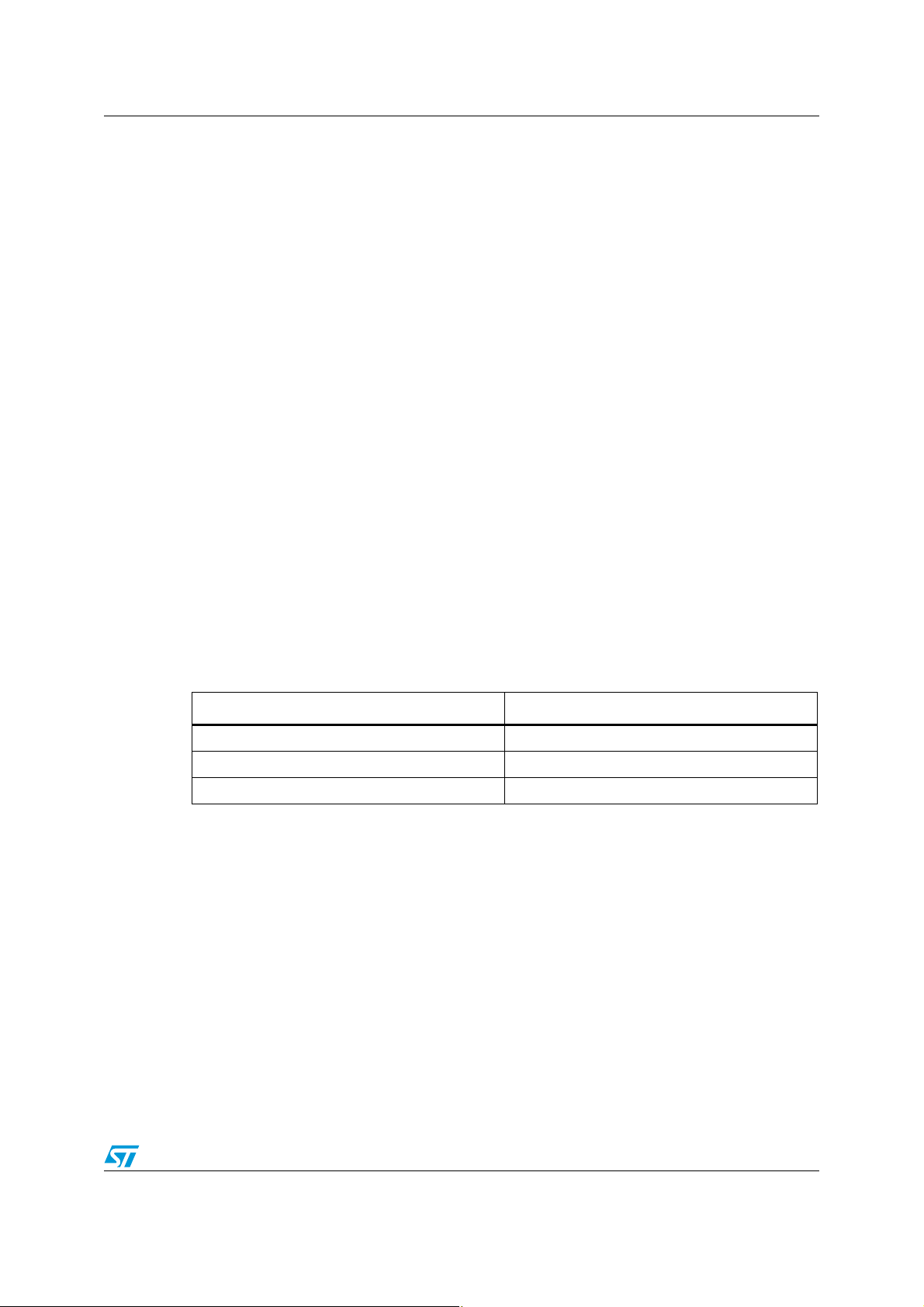
Figure 12. Latchup mechanism and protection
1. Protection is only recommended if latchup risk is identified.
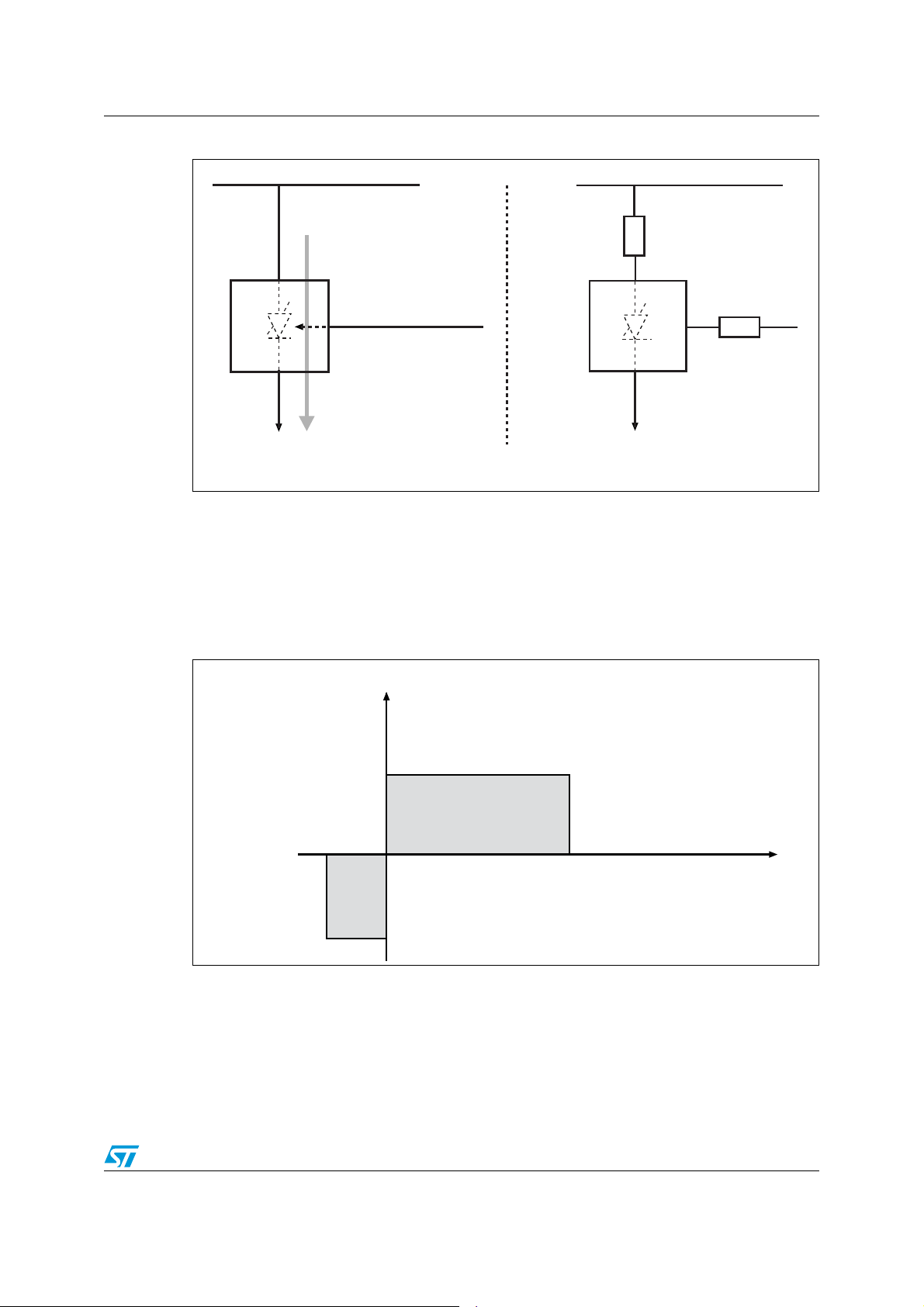
3.2.3 ST EEPROM latchup protection
During the qualification process, samples from three different lots are tested for voltage
overshoots (positive and negative injections). Figure 13 shows the levels of stress applied to
the tested devices.
Figure 13. Latchup test conditions
1. The device does not latch up within the gray areas.
Doc ID 10701 Rev 8 21/69
Page 22

Recommendations to improve EEPROM reliability AN2014
V
POR
VCCmin
V
CC
max
Monotonous rising slope
slower than 1 V/µs
Part locked
by POR
Standby
mode
Operation allowed
time
ai10859b
Voltage
3.3 Power supply considerations
The power supply also has a major impact on the operating reliability of the EEPROM
device.
3.3.1 Power-up and power-on-reset sequence
During power-up, in order for the internal EEPROM reset to be performed correctly, the
application designer has to make sure that the V
monotonously, with a maximum slew rate of 1 V/µs, from V
supply value.
In ST EEPROM devices, the POR (power-on-reset) circuit is activated first as it locks the
part before the internal logic is able to run: at power-up, the device does not respond to any
instruction until V
passes the V
POR
has reached the power-on-reset threshold voltage, V
CC
threshold, the device is reset, in Standby Power mode, but the application
designer should make sure that no instruction is issued to the EEPROM until the power
supply has reached a stabilized value of V
CC
Before a controlled power-down sequence (continuous decrease in V
be placed in the Standby Power mode.
If, for some uncontrolled reason, the power supply drops, it is recommended to carry out a
safe power-down sequence by pulling V
to 0 V, and then to perform a safe power-up
CC
sequence, as described previously. This will secure the device re-initialization.
supply voltage waveform rises
CC
to the final stabilized V
SS
. When VCC
POR
max > VCC > VCCmin (see Figure 14).
), the device must
CC
CC
Figure 14. Power-up
1. Power-up is safe with a monotonous rising slope slower than 1V/µs.
Table 3. Typical POR threshold values
Bus protocol I²C SPI MICROWIRE
Device voltage range All 5 V
POR threshold limits
over the whole
temperature range
22/69 Doc ID 10701 Rev 8
1V ± 0.5V 3V ± 0.5V 1V ± 0.5V 3 V ± 0.5 V 1V ± 0.5V
Other Device
Ranges
5 V
Other Device
Ranges
Page 23

AN2014 Recommendations to improve EEPROM reliability
Voltage supply
EEPROM device
Ai11064b
VCC
V
SS
10 nF < C < 100 nF
50 Ω
3.3.2 Stabilized power supply voltage
The value of the stabilized power supply voltage, including potential variations, must always
stay within the operating V
reliable and guaranteed. Application designers deal mostly with transient peak currents and
voltages. Transient peak current generated by EEPROM during read, write and output buffer
transitions induces transient voltage disturb on power supply lines. Therefore, the use of
high-frequency, low-inductance capacitors located as close as possible to the device V
and V
pins are also recommended. Some applications with a limited power supply driving
SS
capability may require a small value resistor (<50 Ω) connected to the EEPROM V
that the peaks of current sunk by the EEPROM during the write cycle (10 mA typical during
a few nanoseconds, with a duty cycle of less than 1/100) are mostly supplied by the
decoupling capacitor and so, induce less disturbance on the voltage supply line of the
application. See Figure 15.
Figure 15. Local EEPROM supply filtering
range specified in the datasheet, where device operation is
CC
pin, so
CC
CC
1. Capacitor should be placed as close as possible to VCCand VSS pins to avoid parasitic inductive effects.
2. Resistor must never be placed between the decoupling capacitor and the V
3.3.3 Absolute maximum ratings
Absolute maximum ratings are not operating values for the device. They provide an
additional security margin for temporary operating deviations. Temporary operation within
this margin will not cause the device to be damaged. However, the normal operation of the
EEPROM is neither guaranteed nor reliable under absolute maximum rating conditions that
are above or below normal operating conditions.
Doc ID 10701 Rev 8 23/69
pin of the EEPROM.
CC
Page 24

Hardware considerations AN2014
4
4
2
0$
)TYP!
AT6##6
6
##
%3$%/30ROTECTION
%IPIN
AID
4 Hardware considerations
EEPROM connections are essential for an application’s robustness. During Power up,
Power down and Application Reset, input signals must be fully controlled to avoid hazardous
behavior or random operation. For each product family a good hard-wiring design can
protect the parts from uncontrolled behavior.
4.1 I2C family (M24xxx devices)
4.1.1 Chip enable (E0, E1, E2)
The Chip Enable (E0, E1, E2) inputs have an internal pull-down resistor. It is thus possible to
have the three Chip Enable inputs unconnected (Chip Enable address is then decoded as
‘000’). However, this configuration should be avoided since inputs are still prone to antennalike pick-up or other cross coupling effects.
To achieve a robust design, Ei inputs must not be driven dynamically but must be directly
tied to V
The input leakage current on Ei pins depends on the input voltage value (see Ta bl e 4 ).
or VSS.
CC
Figure 16. Chip Enable inputs E0, E1, E2
Table 4. Connecting the Ei inputs of I²C products
I²C products 1 Kbits to 16 Kbits
Typical internal E0, E1, E2 pulldown resistance (RPD)
Input leakage I
of Ei pins
li
Recommended connection of Ei
pins
30 kΩ 100 kΩ 50 kΩ
Ili = 0 for VEi > V
Ili = VEi/RPD for 0 < V
Direct connection to V
32 Kbits to 128
Kbits
CC
256 Kbits to 512
IH
< V
Ei
IH
or V
SS
Kbits
24/69 Doc ID 10701 Rev 8
Page 25

AN2014 Hardware considerations
Ai11088
SDA pad
ESD/EOS Protection
RC Filter
Schmitt trigger
Open-drain Resistor
INPUT
OUTPUT
4.1.2 Serial data (SDA)
The Serial Data (SDA) input/output is a bidirectional signal. The SDA pin is internally
connected to a CMOS Schmitt trigger input buffer and an open drain output transistor (see
Figure 17.). The SDA line must be pulled to the V
(R
). The value of the pull-up resistor depends on capacitive load of SDA line, Master and
PU
EEPROM I/O buffer characteristics. See Ta bl e 5 for calculation rules.
The input pin leakage is negligible (typically a few nA). The input schematic (including
protection circuit) does not offer any open path to the V
can be set before the EEPROM power up and remain high even after Power Down with no
risk of leakage or EOS.
Figure 17. Serial Data input/output SDA
of the device with a pull-up resistor
CC
or VCC therefore the SDA level
SS
Table 5. Calculation rules for pull-up resistor on SDA
Maximum R
Minimum R
1. The smaller RPU, the faster the clock frequency. The higher RPU, the lower the operating current, the
slower the transitions and the lower the electromagnetic interference.
2. Refer to the "Maximum R
PU
PU
value Vs. Bus capacitance" figure in I2C datasheet
L
RPU x C
- V
(V
CC
< SDA rise time (I
load
Maximum value of:
IL EEPROM/IOL Master
(1)
2
C specification is 300ns)
, V
- V
CC
IL Master/IOL EEPROM
(2)
)
Doc ID 10701 Rev 8 25/69
Page 26

Hardware considerations AN2014
4
2
05
6
##
3$!,INE
%%02/-$EVICE
,OWIMPEDANCEPATH2PU
DOESNOTLIMITTHECURRENT
!IB
-ASTERPUSHPULL
OUTPUTBUFFER
2
3
./42%#/--%.$%$3$!"53#/..%#4)/.
Figure 18. SDA bus conflict with push-pull buffers (NOT RECOMMENDED)
1. RS > VCC/IO with IO = min(Master IOH, EE IOL). Without the RS resistor the current is limited by the Master
buffer and transistor T2 producing overstress at both Master and EEPROM side.
On the Master side, the SDA line should be connected to an open drain output. The Master
SDA output must not be a push-pull buffer as this would lead to a conflict when the Master
drives high SDA line and when the EEPROM drives low the SDA line (this induces a high
current between the power supply of the Master and the ground of the EEPROM device).
This event occurs each time when the I
2
C device acknowledges an instruction from the
Master (see Figure 18).
4.1.3 Serial clock (SCL)
The Serial Clock (SCL) input is connected to a CMOS Schmitt trigger input buffer. In
applications with a multiple master configuration, the master must have an open drain output
with an external pull-up resistor. In applications using a single master configuration, SCL
line can be connected to a push-pull buffer. For a safe design, the SCL line must never be
left floating (Hi-Z) and must be driven low when SDA transitions are not under control to
avoid undesired START and STOP conditions. As a consequence, Power up, Power down
phases as well as Reset states, can be secured using a pull-down resistor on the SCL line.
This will minimize the chances of a parasitic STOP/START condition, when the controller
releases the I
The input pin leakage is negligible (typically a few nA). Input schematic (including a
protection circuit) does not offer any open path to V
set before the EEPROM power up and can remain high even after power down with no risk
of high leakage or EOS.
2
C bus.
or VCC. Therefore SCL level can be
SS
26/69 Doc ID 10701 Rev 8
Page 27

AN2014 Hardware considerations
Ai11725
SCL pad
ESD/EOS Protection
Glitch Filter
Schmitt trigger
100ns
WC pin
ai10916b
T
1
T
2
R
PD
I typ = 2.5µA
at VCC = 5V
V
CC
ESD/EOS Protection
Figure 19. Serial Clock input SCL
4.1.4 Write control (WC)
The Write Control (WC) input includes an internal pull-down resistor, in case the application
designer leaves it floating (See Figure 20). If no write protection is necessary, it should be
directly tied to the V
input to a Master output and a pull-up resistor to V
write protection also during the critical Power-up, Power Down and Application Reset phase.
Prior to issuing any Write instruction the WC
maintained Low during the whole operation.
Input pin leakage current depends on input pin voltage. See Tab le 6 .
. The best write protection is obtained by connecting the Write Control
SS
(see Figure 22), thus allowing a default
CC
pin should be driven Low and it should be
Figure 20. Write Control input (WC
)
Doc ID 10701 Rev 8 27/69
Page 28

Hardware considerations AN2014
R
PD
R
PURPD
+
---------------------------- - 0.7≥
R
PU
3R
PD
×
7
-------------------- -<
Table 6. Connecting WC inputs in I2C products
I²C 1 Kbit to 16 Kbits 32 Kbits and more
WC
internal pull-down resistance
(RPD)
(1)
Condition:
15 kΩ 30 kΩ
External pull-up (R
inputs not connected (left
WC
floating)
PU
)
Therefore:
is read as “0”
WC
Ili = 0 for Vi = 0V
Input leakage I
1. These pull-down values can change within the range authorized in the datasheet without previous notice.
li
Ili = Vi/RPD for 0<Vi<V
lli < 5µA for Vi > V
IH
IH
28/69 Doc ID 10701 Rev 8
Page 29

AN2014 Hardware considerations
6
##
%
%
%
6
33
)#%%02/-
6
##
7#
3#,
3$!
'.$
2
,
2
,
N&
6
33
6
##
-36
-ASTER
)#BUS
6
##
)#%%02/-
'.$
K٪
22
,
2
,
%
%
%
6
33
6
##
7#
3#,
3$!
N&
6
33
6
##
-36
-ASTER
)#BUS
4.1.5 Recommended I2C EEPROM connections
Recommended I²C EEPROM connections are shown in Figure 21 and Figure 22. Note that
for both circuits:
1. The decoupling capacitor (10 nF min) must be placed as close as possible to the
package pins V
2. A pull-up resistor should be used only when the WC
unused, the WC
3. The I
2
C specification recommends to connect 220-Ohm serial resistors on SCL and
SDA. They are not useful unless identified overstress is liable to occur on these pins or
electromagnetic disturbances must be reduced.
Figure 21. Recommended I²C connections – safe design
and VSS.
CC
pin is driven by a Master I/O. If
pin must be connected to ground or left floating.
1. The pull-up resistor RL value must be large enough for the I²C master bus to pull WC low (current sink
capability of the I²C master bus I/O).
2. E0/E1/E2 must be connected either to V
or to GND.
CC
Figure 22. Recommended I²C connections – robust design
1. E0/E1/E2 must be connected either to VCC or to GND.
2. The use of external pull-up and pull-down resistors is strongly recommended even if the Master I/Os for the
2
C bus are already providing them. Please refer to Section 6.1.1 for more details.
I
Doc ID 10701 Rev 8 29/69
Page 30

Hardware considerations AN2014
-36
(OLD3#$
%3$%/30ROTECTION
3CHMITT4RIGGER
4.2 SPI family (M95xxx devices)
4.2.1 Chip Select (S)
Chip Select (S) is a CMOS Schmitt trigger input buffer.
For safe design, Chip Select (S
V
outside the communication slots. It is strongly recommended to add a pull-up resistor to
CC
) must never be left floating, and must be constantly held at
ensure a high level on the Chip Select pin at any time and in particular during power-up,
power-down and during the reset phase of the master, since, during these phases, the
master usually leaves its I/Os in high impedance. The pull-up resistance should be
calculated as a function of the bus capacitive load so that the voltage on the S
remains above V
= 0.7VCC during power-up.
IH
pin always
The input pin leakage is negligible, typically a few nA. The input schematics, including the
protection circuit, does not offer any open path to the V
or VCC.
SS
Note: To filter out wrong selections, the M95xxx devices are internally selected only when the
following two conditions are met: S
falling edge and S remains low.
Figure 23. Chip Select, Clock, Data, Hold input pins
4.2.2 Write Protect (W)
The Write Protect (W) signal is a CMOS input used to enable or disable Write protection. To
ensure write protection at Power-up and Power-down, its default state should be low. It is
therefore recommended to add a pull-down resistor (which value must be smaller than the
pull-up resistor on S
the SPI bus in high impedance (power-up, power-down and Master reset phases). In this
case the Write Protect (W
time constant of the W
resistor, see Section 4.2.6: Recommended SPI EEPROM connections), thus preventing the
potential execution of an ongoing write command (Write to memory for 1 Kbit to 4 Kbit SPI
devices and Write Status Register for SPI devices of density above 8 Kbits).
The input pin leakage is negligible, typically a few nA. The input schematic, including the
protection circuit, does not offer any open path to V
30/69 Doc ID 10701 Rev 8
line), to optimize write protection in cases where the controller releases
) line goes low before the Chip select (S) line goes high (since the
pull-down resistor is smaller than the time constant of the S pull-up
or VCC.
SS
Page 31

AN2014 Hardware considerations
Ai11066
W pin
ESD/EOS Protection
Figure 24. Write Protect input W
4.2.3 Serial Data input (D) and Serial Clock (C)
The Serial Data Input (D) and Serial Clock (C) signals are connected to a CMOS Schmitt
trigger input buffer and should be controlled by push-pull buffers (from the SPI master bus).
An external pull-down resistor on Serial Clock (C) signal will prevent “out-of-specification”
configurations like simultaneous rising edges on S
bus (violation of the t
SHCH
and t
timings). An external pull-down resistor on the Serial
CHSH
Data Input (D) (see Figure 27: Recommended SPI connections - robust design) will optimize
the signal control and the device standby current.
and C when the Master releases the SPI
The pull-down resistor value on C is optimized if its value is larger than the pull-up resistor
value on the Chip Select (S
) line. In this case, if the SPI bus is released, the Chip Select (S)
line goes high faster than the Clock (C) line goes low and so deselects the device before the
Clock signal crosses the input buffer trigger point (around V
CC
/2).
The input pin leakage is negligible, typically a few nA. The input schematic, including the
protection circuit, does not offer any open path to the V
or VCC.
SS
Note: If the Clock (C) line cannot be pulled down (and must be pulled up due to other system
constraints), it is recommended to choose a weaker pull-up resistor value (at least three
times weaker) than the pull-up resistor value on the Chip Select (S
of-specification" configuration can also be minimized by connecting the Hold (HOLD
) line. Moreover, the "out-
) pin to
the reset signal (active low) of the Master: if the Master leaves the SPI bus in high
impedance, the Hold (HOLD
) line goes low, locking the Clock to a low level (if already low),
thus preventing the occurrence of a rising edge on both the Clock and Chip Select lines (this
prevents the violation of the t
CHSH
and t
SHCH
timings).
4.2.4 Hold (HOLD)
The Hold (HOLD) is a CMOS Schmitt trigger input buffer used to pause communication. It
should be driven by a push-pull buffer (SPI master bus) for a better timing control, or tied
directly to V
before the EEPROM power up and can remain high after power down. The Hold
not sink a current even if a voltage higher than V
The input pin leakage is negligible, typically a few nA. The input schematic, including the
protection circuit, does not offer any open path to the V
Select, Clock, Data, Hold input pins).
if unused. The hold pin cannot be left floating. The Hold input can be set
CC
input will
is applied to it.
CC
or VCC (see Figure 23: Chip
SS
Doc ID 10701 Rev 8 31/69
Page 32

Hardware considerations AN2014
Ai11067
Q pin
ESD/EOS Protection
1
0
4.2.5 Serial Data output (Q)
The Serial Data Output (Q) is a push-pull tri-state output buffer. The Serial Data Output
being often in the high impedance state and connected to a master input pin, it may be
useful to connect it to a pull-up (or pull-down) resistor to set a default value on the bus and
thus prevent the master input from toggling (see Figure 23: Chip Select, Clock, Data, Hold
input pins). Application designers must be aware that connecting several devices on the
Serial Data Output (Q) increases capacitive load of the line. The access time of the device is
tested with a 100 pF or 30 pF capacitive load, depending on the clock frequency (refer to the
M95xxx device datasheet for the values of the capacitive load and clock frequency).
Figure 25. Output pin tri-state buffer
32/69 Doc ID 10701 Rev 8
Page 33

AN2014 Hardware considerations
6
##
3
1
7
6
33
30)%%02/6
##
(/,$
#
$
'.$
N&
6
##
2
05
6
33
-36
2
0$
-ASTER
30)BUS
6
##
3
1
7
6
33
30)%%02/6
##
(/,$
#
$
'.$
2
0$
KΩ
2
0$
KΩ)
2
05
2
0$
205KΩ
N&
6
33
6
##
-36
-ASTER
30)BUS
2
0$
KΩ)
4.2.6 Recommended SPI EEPROM connections
Recommended SPI EEPROM connections are shown in Figure 26 and Figure 27. Note that
for both circuits:
1. The decoupling capacitor (10 nF min) must be placed as close as possible to the
package pins V
2. S
input is pulled high with RPU and C input is pulled low with RPD. In doing so, if the SPI
master bus leaves S
ensured that clock C remains low or falls low (unlike a case where S and C could rise
together, that is t
3. If unused, the Hold
must never be left floating.
Figure 26. Recommended SPI connections - safe design
and VSS.
CC
and C in high impedance, the SPI EEPROM is deselected and it is
=0, out of a specification event).
CHSH
and W pins must be directly connected to VCC, as a CMOS input
Figure 27. Recommended SPI connections - robust design
1. Q must be connected either to RPD or RPU.
Doc ID 10701 Rev 8 33/69
Page 34

Hardware considerations AN2014
Table 7. Calculation for external pull-up and pull-down resistors in SPI products
EEPROM input pins (S, W, HOLD, C, D) EEPROM output pin Q
R
PD
R
PU
RPD > VIH EEPROM / IOH master RPD > VIH master / IOH EEPROM
RPU > (VCC − VIL EEPROM) / IOL master RPU > (VCC − VIL master) / IOL EEPROM
34/69 Doc ID 10701 Rev 8
Page 35

AN2014 Hardware considerations
Ai11727
S, C, D
ESD/EOS Protection
Glitch Filter
Schmitt trigger
Typical 50ns
4.3 MICROWIRE® family (M93Cxxx and M93Sxxx devices)
Only devices designed for 4.5 V/5.5 V range offer both TTL and CMOS input/output level
compatibility. 2.5 V/5.5 V range products are only CMOS compatible.
4.3.1 Chip Select (S)
The Chip Select (S) input pin is connected to a CMOS Schmitt trigger input buffer (see
Figure 28: Chip Select, Clock, Data input pins). It is recommended that the master bus
controls the Chip select (S) with a push-pull buffer.
S must never be left floating. It is therefore strongly recommended to add a pull-down
resistor to ensure a low level on the Chip Select input at any time, including during periods
when the S line is in high impedance, such as power-up, power-down and the reset phase of
the Master.
It is therefore strongly recommended to add a pull-down resistor to ensure a low level on the
Chip Select pin at any time and in particular during power-up, power-down and the reset
phase of the Master.
The input pin leakage is negligible, typically a few nA. The input schematic, including the
protection circuit, does not offer any open path to the V
Figure 28. Chip Select, Clock, Data input pins
or VCC.
SS
4.3.2 Serial Data (D) and Serial Clock (C)
Serial Data (D) and Serial Clock (C) input pins are connected to a CMOS Schmitt trigger
input buffer (see Figure 28).It is recommended the Master bus controls them with a pushpull buffer. An external pull-down resistor (R
an “out-of-specification” configuration such as a clock rising edge while Chip Select goes
low when the Master releases the bus (Hi-Z state, violation of the t
pull-down resistor on Serial Data Input (D) will optimize signal control and standby current.
Pull-down resistor values on Serial Clock (C) and Serial Data (D) are optimized if they are at
least three times bigger than the pull-down value on the Chip Select (S) line. In this case, if
the SPI bus is released, the Chip Select (S) line goes Low faster than the Clock (C) line
goes low, and so, deselects the device before the Clock signal crosses the input buffer
trigger point (area around V
/2 is always sensitive).
CC
Doc ID 10701 Rev 8 35/69
) on a Serial Clock (C) signal will prevent from
PD
timing)). An external
SLCH
Page 36

Hardware considerations AN2014
Ai11089
ORG pin
ESD/EOS Protection
(1)
If the Clock (C) line cannot be pulled down and must be pulled up due to other system
constraints, it is recommended to choose a weaker pull-up value (at least three times
weaker) than the pull-down value on Chip Select (S).
The input pin leakage is typically a few nA. The input schematic, including the protection
circuit, does not offer any open path to the V
or VCC.
SS
4.3.3 Organization Select (ORG)
ORG is not a CMOS input. If left floating, it is interpreted internally as being High. It is
strongly recommended to connect it directly to the V
dynamically implies that application software can handle specific MICROWIRE dual
organization and switch from Single data byte management to word data management.
or VSS pin of the device. Driving it
CC
The input pin leakage is negligible,
including the protection circuit, does not offer any open path to the V
in standby mode, typically a few nA. The input schematic,
or VCC. (See
SS
Figure 29)
Figure 29. Organization input ORG
1. The Pull up is switched off in standby mode. Pull up is only active for a short time at chip select to ensure 1
level is latched when ORG is floating.
4.3.4 Serial Data output (Q)
It is a push-pull tri-state output buffer. As the Serial Data Output is often in the Highimpedance state and connected to a Master input pin, it may be useful to connect a pull-up
resistor to set a default value (corresponding to the Ready state) on the bus and thus
prevent the Master input from toggling. Application designers must be aware that connecting
several devices on Serial Data Output (Q) increases the capacitive load of the line. Access
time of M93C ST EEPROM is tested with 100pF load (see Figure 25: Output pin tri-state
buffer)
4.3.5 Don’t use (DU)
Pin does not contribute to the normal operation of the device. It is reserved for use by
STMicroelectronics during test sequences. The pin may be left unconnected or may be
36/69 Doc ID 10701 Rev 8
Page 37

AN2014 Hardware considerations
6
##
3
#
$
1
-)#2/7)2%%%02/-
6
##
$5
/2'
6
33
'.$
2
0$
2
05
N&
6
##
6
33
-36
-ASTER
BUS
6
##
3
#
$
1
-)#2/7)2%%%02/-
'.$
205K٪
6
##
$5
/2'
6
33
N&
6
##
6
33
-36
20$KΩ
2
0$
KΩ
2
0$
KΩ
-ASTER
BUS
connected to VCC or VSS. No other connection is allowed. Direct connection of DU to VSS is
recommended for the lowest standby power consumption mode.
4.3.6 Recommended MICROWIRE EEPROM connections
Recommended MICROWIRE EEPROM connections are shown in Figure 30 and Figure 31.
Note that for both circuits:
1. A decoupling capacitor (10 nF min) must be placed as close as possible to the package
pins V
2. A 50 Ohm resistor can be connected to V
identified latchup risk is to be minimized.
Figure 30. Recommended MICROWIRE connections - safe design
and VSS.
CC
if extra filtering on VCC is needed or if an
CC
Figure 31. Recommended MICROWIRE connections - robust design
Table 8. Calculating external pull-up and pull-down resistors in MICROWIRE products
Recommended
connection
EEPROM input pins (S, C, D, W
R
PD
R
PU
RPD > VIH EE / IOH master RPD > VIH master / IOH EE
RPU > (VCC − VIL EE) / IOL master RPU > (VCC − VIL master) / IOL EE
Doc ID 10701 Rev 8 37/69
, ORG) EEPROM output pin Q
Page 38

Hardware considerations AN2014
V
CC
V
SS
+
-
Other ICs
EEPROM
1 µF < C2 < 100 µF
10 nF < C1 < 100 nF
GND
V
CC
Ai11079b
4.4 PCB Layout considerations
The full system layout becomes ever more critical because of space constraints, high
communication speed, noise due to interference and all EMC constraints.
4.4.1 Cross coupling
The cross coupling effect increases with the frequency and fine PCB technology. All floating
signals or pins, weak pull-up or pull-down connections are very sensitive to cross coupling
and antenna-like pick-up. All unused pins should be tied correctly (in general to V
4.4.2 Noise and disturbances on power supply lines
Noise and disturbances on power supply lines must be filtered out. For a robust design it is
recommended to place local decoupling capacitors. Low inductance capacitors in the range
of 10nF to 100nF are usually preferred.
Electrolytic capacitors in the range of 1µF to 100µF should also be placed close to the
power supply source of the system.Avoid Ground and V
the sensitivity to electromagnetic fields. (See Figure 32: PCB decoupling.)
Figure 32. PCB decoupling
CC
loops on the PCB as it increases
or VSS).
CC
38/69 Doc ID 10701 Rev 8
Page 39

AN2014 Software considerations
5 Software considerations
The purpose of the suggestions presented below is to help the application designers make
the most of ST’s EEPROM products, and to help to improve the system robustness and
compatibility with future EEPROM devices.
5.1 EEPROM electrical parameters
Low-level drivers (hardware dependent) must follow the EEPROM electrical parameters for
correct communication. EEPROM samples are not absolute references for software
validation as they are not representative of production variations. The EEPROM timings
given in the device datasheets are unique reference characteristics. They correspond to
minimum and maximum timing values to be taken into account for hardware and software
calibration.
Typical errors to be avoided in applications are:
● Input voltage levels not compatible with the specifications, V
V
>0.7VCC.
IH
● Excessive current requested from EEPROM data output buffer (output CMOS levels
are no more guaranteed).
● Write time not observed (t
● Data setup time in applications using high clock rate or very smooth waveforms with
= 5 ms) before issuing a new command.
W
slow transitions. As a general recommendation, signal rise and fall time must be less
than 10% of the clock period.
● Out of specification (too short) pulses on the Clock signal, Chip select signal or on
Start/Stop conditions.
<0.3VCC and
IL
The behavior of EEPROM devices operating “out of specification” can never be guaranteed
and is not always predictable. Moreover, major compatibility issues may arise when
switching to a new device version or using a compatible device from another supplier. When
using a double source supplier for EEPROMs, the worst value of each single timing should
be used as a reference for direct compatibility.
5.2 Optimal Write control
EEPROM devices are simple products with few operating modes and instructions. It is
nevertheless worth focusing on the features that can be used to improve performance and
application robustness.
Doc ID 10701 Rev 8 39/69
Page 40

Software considerations AN2014
5.2.1 Page mode
The memory array is divided into pages. The size of a page is given on the first page of the
product datasheet (it can be 8, 16, 32, 64, 128 or 256 bytes).
The Write Page mode is used to write a block of data bytes in a single shot. The Write Page
mode sequence consists of a write instruction with the start address and one or more data
bytes directly followed by the internal execution of the operation (t
● The maximum number of bytes programmed during a Write Page is limited by the page
length of the product.
● A data block can be programmed starting at any offset inside the page.
● The address of the first data byte to program is given in the instruction, other data bytes
are programmed in consecutive addresses.
● If the last page address is reached when shifting in the data bytes, the internal address
pointer rolls over to the first byte inside the same page. It is therefore not possible to
store data in two different pages with a single Write Page instruction.
● If more data bytes than the page length (for instance 32) are shifted in, only the last
data bytes (last 32 bytes) are programmed in the page (The 33
will replace the 1
st
data byte shifted in and so on).
To write to the EEPROM, it is recommended to use the Page mode instead of the byte mode
whenever possible. The programming time (t
) is independent of the number of bytes to
W
program and the Page mode has two main advantages:
1. It speeds up the application when storing or updating data.
2. It minimizes the high-voltage programming stress and naturally extends the cycling
endurance.
).
W
rd
data byte shifted in
5.2.2 Data polling
Data Polling is a very safe way of managing the EEPROM Write time (tW). The aim is to
check the EEPROM status before sending the next instruction, so as to prevent bad masterslave communications.
Data polling is a software loop used to optimize the write wait time and control the correct
operation of the device. Moreover, software which has data polling will be able to adapt to
different devices
This algorithm must be coupled to a timeout counter to limit the data polling time and avoid
endless process.The timeout limit should be higher than the maximum write time of all
devices used (typically 15 ms should be enough).
regardless of the specified write time.
40/69 Doc ID 10701 Rev 8
Page 41

AN2014 Software considerations
Ai11083
START
Device Code
(R/W = 0)
ACK?
STOP
Ready for new command
Yes
No
Write in Progress
(1)
(Re)START
I2C products
In I2C products, the device does not respond (NoAck) when a programming operation is in
progress. Data polling thus consists in sending a Device Code in a loop mode and tracking
the EEPROM acknowledgement. It is recommended to poll the device with a Write
instruction.
Figure 33. I
2
C data polling algorithm
1. Using the READ Device code (R/W = 1) is hazardous due to I2C protocol constraints.
Doc ID 10701 Rev 8 41/69
Page 42

Software considerations AN2014
!IB
3ELECT3
2$32COMMAND
$ESELECT3
7)0BIT
$ESELECT
3
2EADYFORNEWCOMMAND
7RITEIN0ROGRESS
SPI products
In SPI products, a specific instruction (Read Status Register - RDSR) is used to check the
status of the WIP (Write In Progress) bit in the Status Register. A loop on the RDSR
command (RDSR instruction + Data byte) checks the WIP bit status. As soon as it returns to
"0", the device is ready to accept new commands. For compatibility reasons, it is
recommended to send the full RDSR command each time instead of continuously reading
the status register.
Figure 34. SPI data polling algorithm
1. Although ST EEPROM allow continuous read of the status register it is, for compatibility reasons,
recommended to send each time the full RDSR command
42/69 Doc ID 10701 Rev 8
Page 43

AN2014 Software considerations
Ai11081
Write in Progress
Select (S=1)
Deselect (S=0)
Ready/Busy
on Q pin
Q level
Deselect (S=0)
Ready for new command
Low
(1)
High
(2)
MICROWIRE products
In MICROWIRE products, the Data Output pin (Q) indicates the Ready/Busy status when
the Chip Select pin (S) is driven High. Once the device is ready, the Q output goes highimpedance (Hi-Z) after a Start Condition. It is strongly recommended to not operate the
Clock during the data polling sequence because as soon as the chip is ready, the logic will
start to decode incoming bits.
Figure 35. MICROWIRE data polling algorithm
1. There is no difference in the data polling process if chip is deselected between 2 ready/busy checks.
2. It is strongly recommended not to operate the Clock during the data polling sequence because as soon as
the chip is ready, the logic will start to decode incoming bits.
Doc ID 10701 Rev 8 43/69
Page 44

Software considerations AN2014
5.3 Write protection
5.3.1 Software write protection
Use the software write protection features to protect sensitive data items:
● I²C products do not have a software write protection.
● In SPI products, 2 non-volatile Status Register bits (BP0, BP1) are dedicated to the
software write protection. The upper quarter, the upper half or the whole memory array
can be set as Read-Only.
● In 1 Kbit to 4 Kbit M93Sxxx MICROWIRE products the amount of data to protect is
directly set by a user instruction. The selected area becomes a Read-Only memory.
Data items like trace codes, identification codes, manufacturing configurations, default
parameters and all sensitive data in general, can be software protected against corruption
during field service. Software protection bits and registers are limited in terms of cycling and
data retention in the same way as memory array bits.
5.3.2 Hardware write protection
By default the hardware write protection feature should be set and the time during which the
device is left unprotected should be limited to the time required to issue and execute Write
instructions. The hardware write protection is very effective against parasitic or hazardous
instructions transiting on the interface bus.
Also use the hardware write protection features during Power-up, Power-down and normal
operation (Refer to the Hardware considerations).
● The WC pin in I²C products protects the entire array.
● The W pin protects the entire array by resetting the Write Enable Latch (WEL) bit in 1
Kbit to 4 Kbit SPI products whereas it protects the non-volatile bits of the Status
Register in 8 Kbit to 512 Kbit SPI products.
It is recommended to change the state of the Write Protect pin only if no data transfer or
program cycle is in progress. The Write Protect and Write Control pins should be controlled
with very conservative timings:
● 1 clock cycle time clearance (with no data transfer) before the select (or start) event
● 1 clock cycle time clearance (with no data transfer) after the deselect (or stop) event
● Wait for the write cycle to complete (t
) before changing the protection
W
This conservative sequence will not affect the communication speed but will ensure the safe
operation of the products (see Figure 36 and Figure 37).
The Write Protect (W
) signal for SPI, or Write Control (WC) signal for I²C are glitch sensitive
and a short (parasitic) pulse could cause a write request to be aborted. This feature can also
be of great help in emergency situations like power loss or Master reset. See the Power
supply loss and application reset section for details.
44/69 Doc ID 10701 Rev 8
Page 45

AN2014 Software considerations
Clearance
1 Clock Period
Clearance
1 Clock Period
ai10921
WC
START + WRITE +ADDRESS + DATA + STOP
t
W
< 5msSDA
Clearance
1 Clock Period
Clearance
1 Clock Period
ai10922
W
WRITE +ADDRESS + DATA tW < 5ms
SDA
S
WREN
Polling
Figure 36. .Recommended use of the WC pin in I²C products
Figure 37. Recommended use of the W
5.4 Data integrity
In automotive applications, the implementation of a data integrity strategy is mandatory.
Several strategies are possible, but whatever the solution used, extra memory density is
required to hold the extra data.
5.4.1 The checksum
It is perhaps the more commonly used method to prevent data loss, data corruption and
poor communication. It consists in computing a checksum of the data to write and in storing
it into the memory array as an additional data byte. Checksums are particularly suitable for
the secure communication of parameters that are often read and updated.
pin in SPI products
To give applications more robustness, more elaborated checksum routines like Error Code
Correction can also be used to correct detected errors.
Doc ID 10701 Rev 8 45/69
Page 46

Software considerations AN2014
D0 D1
D1 D0
Dn Dn – 1
Dn – 1 Dn
Reference Data
Duplicated Data
ai10923b
Rows or Pages
Columns
5.4.2 Data redundancy
It is also a good way of preventing data loss and data corruption. Data redundancy is more
particularly adapted to the read-only data stored in the EEPROM. Typically, this kind of data
is programmed once during module manufacturing and then only read during the whole
application lifetime. As the data is never refreshed, there is a higher probability of facing a
retention problem due to device defect or external disturbing factors. With redundancy, there
is a backup on each read-only byte.
The efficiency of Redundancy depends strongly on the physical structure of the memory. As
described previously, the memory array is organized as rows (or pages) and columns where
each byte location (address) is the intersection of a row and a column. Two redundant data
items should not share the same row (or page) and column but should be located at
physically independent addresses (see Figure 38).
The following rules should be kept in mind by the designer:
● The redundant data should not be in the same page or column as the page or column
of reference.
● The address of the duplicated data should differ from original address by at least 1 bit
in the column address and 1 bit in the page address (see Table 9: Column and page
address bits according to page length).
Note: More detailed information on memory array, data scrambling and address decoding are
available on request.
Table 9. Column and page address bits according to page length
Page length Column address bits Page address bits
Page of 16 bytes 4 LSB bits All other MSB bits
Page of 32 bytes 5 LSB bits All other MSB bits
Page of 64 bytes 6 LSB bits All other MSB bits
Page of 128 bytes 7 LSB bits All other MSB bits
Figure 38. Example of how to duplicate data safely
1. N = Page length (number of bytes defining a page);
Di = Data byte at page location "i" (i < N);
n =multiple of 4 (n < N).
46/69 Doc ID 10701 Rev 8
Page 47

AN2014 Software considerations
5.4.3 Checksum and data redundancy
Combining checksums and data redundancy is the best strategy.
Applying the redundancy and checksum strategy to read-only data (2 or 3 copies with a
checksum byte for each data block) improves the EEPROM robustness and, with it, data
integrity.
For cycled data, the checksum strategy is better suited than redundancy (data redundancy
is not recommended as it increases the number of bytes cycled and so, it statistically
increases the probability of fail by cycling stress).
5.4.4 Extra redundancy
Default backup parameters can also be stored in another non-volatile external or embedded
Flash memory. The micro should then have the ability to copy back the data in the EEPROM
when necessary.
Doc ID 10701 Rev 8 47/69
Page 48

Software considerations AN2014
5.5 Cycling endurance and data retention
Even if EEPROM devices are able to withstand a very high number of write cycles, the
EEPROM should not be used in replacement for a non-volatile RAM buffer. The cycling
budget during application life has to be considered.
5.5.1 Values specified in device datasheets
The rated values given in the datasheets are the following:
● Maximum number of write cycles: 1 million cycles at 25 °C.
● Data retention at 55 °C: higher than 40 years.
Note: The specified value is 4 millions at 25 °C for automotive products identified by the process
letter K (F8H process technology).
Cycling qualification
During the cycling qualification, ST EEPROM devices are submitted to a dedicated test
program which allows to program in one single write cycle the whole memory array with the
same byte value. ST can thus guarantee that, for each write operation performed with this
test program:
● each memory array cell is cycled once.
● the logic that controls the write cycles and the associated internal voltages is cycled
once.
Data retention qualification
The data retention qualification tests check that the data written to the EEPROM remain
available with a correct programming level after a bake at 150 °C during 1000 hours (high
temperature significantly accelerates the data retention drift).
5.5.2 Optimal cycling with ECC (error correction code)
Some ST EEPROM devices feature an internal ECC (error correction code) logic which
improves data retention performance. This ECC logic must be taken into account when
defining the application cycling budget.
The ECC logic compares each group of 4 bytes with the corresponding 6 additional
EEPROM ECC bits. As a result, if a single bit out of 4 bytes of data happens to be erroneous
during a read operation, the ECC detects it and replaces it by the correct value in the stream
of read data. The EEPROM cell read reliability is therefore improved by using this feature.
However even if a single byte has to be written, 4 bytes are internally modified (plus the ECC
bits), that is, the addressed byte is cycled together with the three other bytes making up the
group.
48/69 Doc ID 10701 Rev 8
Page 49

AN2014 Software considerations
For example:
● Writing one byte at address 0000h internally programs this byte plus the 3 following
bytes and ECC bits.
● Writing the next byte at address 0001h internally programs this byte plus the 3
contiguous bytes (address 0000h, 0002h, 0003h), and the ECC bits.
● Writing the next byte at address 0002h internally programs this byte plus the 3
contiguous bytes (address 0000h, 0001h, 0003h), and the ECC bits.
● Wring the next byte at address 0003h, internally programs this byte plus the 3
contiguous bytes (address 0000h, 0001h, 0002h), and the ECC bits.
This example shows that each byte was cycled 4 times, although each byte was written only
once. We can therefore conclude that writing data by groups of 4 bytes benefit of the highest
number of write cycles.
Note: A group of 4 bytes is composed of bytes located at addresses [4*N, 4*N+1, 4*N+2, 4*N+3],
where N is an integer.
Refer to AN2440 “Consequences of the embedded ECC on the EEPROM behavior” for
more details concerning the ECC.
Doc ID 10701 Rev 8 49/69
Page 50

Software considerations AN2014
100
1000
10000
25 50 75 100 125 150
1
0
³
c
y
c
l
e
s
cycling temperature (°C)
Writ e / Erase cycles versu s tem peratu re
wearout limit
Risky
application
Safe
application
(above line)
(below line)
5.5.3 Cycling and temperature dependence
Write cycling and retention endurance are independent of the value of VCC (on ST products)
but directly depend on the operating temperature. The higher the temperature, the lower the
cycling performance. Refer to Section 1.1.3: Cycling limit of EEPROM cells.
EEPROM intrinsic failure limit
In Figure 39, the red line represents the maximum write cycling limit, considering that one
cell (or less) per million can fail. This failure rate criteria of 1 cell per million is not a quality
indicator but only a criteria to determine the intrinsic cycling capability of the product. When
performing cycling trials for EEPROM product qualifications, the failure rate is 0 until the
intrinsic capability of the cells is reached. At this point the cells reach the end of their lives
and the intrinsic failure rate becomes exponential as a function of the write cycles.
Therefore the cycling limit shown here has to be considered by system designers as a
maximum cycling value for each byte of the memory. Being above this limit is not
recommended as the intrinsic capability of the cells is exceeded.
Figure 39. Write cycling versus temperature
EEPROM extrinsic failure limit
When an EEPROM assembled on a system fails after a few cycles, it is due to extrinsic
factors like manufacturing defects or specific application stresses. Extrinsic failures are not
considered here as they cannot be measured during ST qualification tests.
Note: Extrinsic factors are the main contributors to the EEPROM quality failure rate observed by
our customers.
50/69 Doc ID 10701 Rev 8
Page 51

AN2014 Software considerations
5.5.4 Defining the application cycling strategy
Regarding the cycling endurance, EEPROM users should be aware that the memory cells
are the limiting factor. ST EEPROM products have no build-in function to limit cycling and
therefore application designers have to evaluate the number of write cycles executed during
the life of the end application. To ensure the safest conditions, it is strongly recommended to
define a temperature profile of the write cycles performed by the EEPROM.
● Define the main temperature stages at which the EEPROM is operating in the end
application.
● For each temperature, estimate the number of write cycles executed for each data
block.
● For each data block (with different cycling profiles), calculate the cumulated cycling
effect using Tab le 1 0 .
Table 10. Application cycling profile evaluation
Temperature Number of cycles
25 °C w (w/1M) × 100 = a%
55 °C x (x/600K) × 100 = b%
85 °C y (y/300K) × 100 = c%
(1)
(2)
% of specification max
125 °C z (z/150K) × 100 = d%
Total w + x + y + z a + b + c + d%
1. The table can be adapted according to the temperature profile by taking care of putting down the maximum
cycling for each temperature (using Figure 39).
2. w, x, y and z are the forecast number of cycles for a specific data block.
If the total percentage of cumulated cycles (last row in Ta b le 1 0 ) is lower than 100%, the
data stored in the EEPROM are safely cycled.
If the total percentage of cumulated cycles is above 100%, the intrinsic safe margin for
cycling is exceeded and a data relocation strategy must be defined.
Cycling on each EEPROM cell is limited as shown in Figure 39 but the number of cycles is
not limited at device level. On this basis it is possible to define a data relocation strategy by
distributing the total number of cycles over several memory locations as follows:
● Define a cycling limit for each data block according to the application needs and
product performance (see Tab l e 1 0).
● Count the numbers of cycles executed on each data block (counter value can be stored
in the EEPROM).
● When the counter exceeds the defined limit, the cycled data block must be relocated to
another physically independent memory address. The software developer should not
move it to a location in the same page (when possible, not in the same column either)
as the reference column/page. This means that the 2 addresses should differ by at
least 1 bit in the page address and, if possible, by 1 bit in the column address. See
Ta bl e 9 . for page and column address bits. The counter is then reset and must also
change address.
Doc ID 10701 Rev 8 51/69
Page 52

Software considerations AN2014
In addition, to optimize the number of cycles in the EEPROM and preserve the other data
blocks in the memory array:
● define data groups or classes (located in the same page) where data with similar
update rates are gathered together. This will optimize the use of the Page mode
instead of the byte mode.
● the area containing the read-only parameters and the cycled items should be
separated and made independent as much as possible. Two types of data should not
share the same pages and, where possible, not the same columns.
Following the above rules, in laboratory environment, ST EEPROM devices have
demonstrated to reach hundreds of millions of cycles, safely.
5.5.5 Overall number of write cycles
As explained above, each EEPROM cell must not be cycled more than the 1 million times
(at 25 °C). However, the overall number of cycles executed by the memory can exceed this 1
million limit as several memory blocks can be cycled individually 1 million times.
Characterization trials are performed only on medium and large density EEPROMs, as
these products can be partitioned in blocks which can be individually cycled 1 million times
during the application life.
For products equal or larger than 32 Kbits and identified with process letter K, the overall
number of cycles at 25 °C is 128 Mcycles.
52/69 Doc ID 10701 Rev 8
Page 53

AN2014 Power supply loss and application reset
6 Power supply loss and application reset
6.1 Application reset
During the application runtime, the Master may be reset by some external reset condition
like a watchdog timer, a power supply monitor, or an ESD. In such case, the serial bus is not
controlled (it is left floating) while the power supply stays stable at its nominal value. When
this occurs, the challenge is to either control the completion of the ongoing write cycle or to
stop the communication with the EEPROM.
When the Master reset is reset, the EEPROM can be:
● deselected in Standby mode. This is the best and safest case. The EEPROM was in
the Idle state and will keep this state if the hardware connections are correct. The
EEPROM will be ready to accept any new command when the Master is restarted.
● deselected while performing an internal write cycle. It is not a problem as at the end of
the self-timed internal write process, the device returns to the standby state. Note that if
the Master restarts while the EEPROM is still programming, the Master has to check
that the EEPROM is ready by issuing a write cycle polling sequence.
● selected while receiving a command or answering to a Read command. This case has
to be handled specifically according to the EEPROM protocol family.
The solutions discussed hereafter concern only the case where an EEPROM is selected.
The aim of these recommendations is to properly stop the communication with the device in
order to avoid further potential disturbances.
6.1.1 I2C family
The basic principle to protect an I2C transaction is to avoid issuing a Stop condition when a
reset occurs. This is because a Stop condition can be decoded as the trigger of an
undesired write cycle if this Stop condition occurs at the end of a data byte, inside a Write
command request.
On the other hand, the Start condition is a safe event as it resets the internal state machine,
and is decoded at any time.
Smart connections on the I
when the Master is reset (I
enters the high impedance state (Master reset).
2
C bus lines help to avoid misunderstanding the Stop condition
2
C bus in high impedance), as described in Figure 40: I2C bus
Doc ID 10701 Rev 8 53/69
Page 54

Power supply loss and application reset AN2014
Figure 40. I2C bus enters the high impedance state (Master reset)
R
L
SCL
SDA
R
L
SCL
SDA
SCL
SDA
Case 1: Pull-up + pull-up resistors
SCL
R<R
L
SDA
Case 2: Pull-up + pull-down resistors
R
L
Case 1a: Might be decoded
as a Stop condition
SCL
SDA
Safe
Case 2a: Don't Care (safe) Case 2b: SCL reaches "0" before the
It is important to note that when the Master is reset and releases the I
used pull-up resistors on the SCL and SDA pins (case1) increase the probability of sourcing
an erroneous Stop condition. The recommended I
2
C connections for a robust design are
Case 1b: Decoded as a
Stop condition
SCL
SDA
Safe
rising edge of SDA = Don't Care (safe)
Ai11090b
2
C bus, the commonly
also detailed in Section 4.1.5.
When the transmission of an I
2
C bus command is interrupted before completion (before the
Stop condition), the EEPROM is paused in its communication until the Master is able to
restart. Before accessing the EEPROM, the Master must follow the sequence below:
● Master must first send a re-synchronization sequence to the EEPROM. It consists of 9
START conditions + 1 STOP condition to re-initialize the internal state machine and
deselect the device safely. Refer to AN1471 for any help to implement this sequence.
● Master must check that EEPROM is ready (no write cycle in progress) by sending a
data polling sequence. Refer to Section 5.2.2: Data polling.
● For the first read access to the EEPROM, it is recommended to define the internal
address pointer with a Random Read instruction.
These recommendations allow to maximize the control on the EEPROM in case of
inadvertent Master reset.
54/69 Doc ID 10701 Rev 8
Page 55

AN2014 Power supply loss and application reset
Ai11091c
R
R
C
Safe
SPI bus connections SPI bus waveforms when the bus enters
the high-impedance state
Safe
S
C
S
(1)
6.1.2 SPI family
Main recommendation for protecting an SPI transaction is to deselect the device in a safe
way. The chip must be deselected taking care of the timings of Chip Select respect to the
Clock rising edge.
● Smart connections of EEPROM pins help to avoid deselect timing violation (t
t
) when Master releases SPI bus. Refer to Section 4: Hardware considerations
CHSH
section for safe recommendations. At deselect, EEPROM will go into the standby state
(see Figure 41: SPI bus enters the high impedance state (Master reset)).
● However, a write cycle may be triggered if the EEPROM is deselected between two
data bytes of a write instruction. On 4-Kbit or lower-density SPI device, setting the W
pin to Low before deselecting the memory will prevent the write cycle execution.
● When Master restarts, it must run a data polling sequence to check that EEPROM is
ready (no write cycle in progress).
● As soon as the SPI device is ready, a WRDI instruction must be issued if the WEL bit in
Refer to Section 5.2: Optimal Write control.
the Status Register is still set to 1. In so doing, the device is protected against any
parasitic write instruction.
These recommendations will maximize the control on the EEPROM in case of inadvertent
Master reset. Recommendations for Master restart can also be the default sequence each
time Master comes out of the reset state like after Power up.
CHSL
and
Figure 41. SPI bus enters the high impedance state (Master reset)
1. A pull-down resistor on C prevents any t
rise at the same time, inducing t
SHCH
timing violation (as a pull-up resistor on C causes C and S to
SHCH
= 0).
Doc ID 10701 Rev 8 55/69
Page 56

Power supply loss and application reset AN2014
6.1.3 MICROWIRE family
Main recommendation for MICROWIRE products is to deselect the device in a safe way. The
chip must be deselected taking care of the timings of Chip Select respect to the Clock rising
edge.
● Smart connections of EEPROM pins help to avoid deselect critical configurations when
Master releases MICROWIRE bus. Refer to Section 4: Hardware considerations
section for safe connections. At deselect, EEPROM will go into the standby state (see
Figure 42: MICROWIRE bus enters the high impedance state (Master reset)).
● However when deselecting the EEPROM, a write cycle may be triggered if the
EEPROM is deselected between two data bytes of a write instruction.
● When Master restarts, it must run a data polling sequence to check that EEPROM is
ready (no write cycle in progress).
● As soon as device is ready, an Erase/Write Disable (EWDS) instruction must be issued
to disable any WRITE instruction. In this way, the device is protected against any
parasitic WRITE instruction.
These recommendations will maximize the control on the EEPROM in case of inadvertent
Master reset. Recommendations for Master restart can also be the default sequence each
time Master comes out of the reset state like after Power up.
Figure 42. MICROWIRE bus enters the high impedance state (Master reset)
MICROWIRE bus connections
S
C
R
(1)
R
1. A pull-down resistor on C prevents any t
the same time as S goes low, inducing t
MICROWIRE bus waveforms when the bus enters
S
C
SLCH
SLCH
the high-impedance state
S
C
Safe
timing violation (as a pull-up resistor on C causes C to rise at
= 0).
Safe
Ai11092c
56/69 Doc ID 10701 Rev 8
Page 57

AN2014 Power supply loss and application reset
6.2 Power supply loss
Data integrity of Non-volatile memory is very often critical as applications rely on it for
system start up and configuration. Power loss is critical for an EEPROM device when a
Write instruction is being issued or executed. In this event, the on-going write request or the
internal write process in the EEPROM may not have completed, leading to data corruption
and data inconsistency.
6.2.1 Hardware recommendations
Application designer will find below some guidelines and recommendations to handle in the
best conditions power supply loss on systems designed with STMicroelectronics EEPROM
memories.
The power supply must de designed in such a way that power loss is detected and backup
supply is supplied for a time allowing safe emergency ending of the system operations. The
list below gives some useful elements to build a robust power management system:
● use voltage regulators including an output voltage sensor. It gives power loss
information to the Master before the supply is too low for system operation.
● use available MCU features such as the Auxiliary Voltage Detector and External
Voltage Detector pin to create a delay between the detection of the low voltage and the
system reset.
● use diodes, bipolar transistors or analog switches to create specific areas with backup
power capacitors.
The extra delay time gained should be used either to allow for the EEPROM to complete any
on-going write process or to allow for the Master to finish or interrupt safely the current
communication with the EEPROM. In a running application it is not possible to distinguish
these two possibilities, therefore the below recommendations must be considered all
together.
6.2.2 Supply voltage energy tank capacitor
In case of inadvertent power loss, applications are very often faced with the situation where
the EEPROM is operating while power supply is falling down.
It is not recommended to operate the device and in particular to initiate write operations
when the device is undergoing steady V
handle write cycles during smooth power supply transitions. A power supply transition is
considered smooth when it allows a complete write cycle to be completed while V
continuously falling or rising within the authorized V
possibility, a power backup capacitor can be designed to allow for the EEPROM to complete
its on-going self-timed write operation in case of inadvertent power loss.
The capacitor value is calculated so as to allow for the full write cycle to be executed:
● l is the EEPROM supply current (I
● t is the EEPROM write time (t
● U is the voltage drop from the nominal value to V
W
Q = C × U = I × t => C = (l × t) / U
transitions. ST EEPROM devices can however
CC
max)
CC
)
range. Taking advantage of this
CC
min of the EEPROM
CC
CC
is
For instance:
C = (3 mA × 5 ms) / 2 V = 7.5 µF
Doc ID 10701 Rev 8 57/69
Page 58

Power supply loss and application reset AN2014
Ai11753
EEPROM
Vcc
Vss
C
5V
on
-
+
Figure 43. EEPROM power backup capacitor
1. Sometimes filtering capacitors placed after voltage regulators, are big enough to allow the EEPROM
device to finish the write operation. In this case, backup capacitors are no longer necessary.
For a complete and detailed calculation, the discharge current through the MCU protection
diodes must be taken into account. The EEPROM inputs/outputs do not draw any current
during write operations and only the pull-up resistors connected to the EEPROM V
CC
pin
will discharge the backup capacitor through the MCU connection.
Optimum robustness is obtained by adding a discharge path to ground. At power-down, the
EEPROM is usually in the standby mode, where it draws little current (no more than a few
µA) and the backup capacitor takes a long time to discharge. The system designer must
either:
● take into consideration the long discharge time to allow the EEPROM V
supply to
CC
reach ground level before switching the system on again or
● add a discharge path to ground to accelerate the discharge if the system may or must
be re-started after a short time
When applying this recommendation, please read also Section 3.3.1: Power-up and power-
on-reset sequence.
58/69 Doc ID 10701 Rev 8
Page 59

AN2014 Power supply loss and application reset
Ai11093b
WC
1 Clock Period
START (1) + ....…. + START (9) STOP
~110µs, at Fc=100kHz Tw = 5ms
Obtaining power loss
information
Effective power loss
6.2.3 Interruption of an EEPROM request
When the Power loss occurs while Master is still sending a command, it is recommended to
have an emergency software procedure able to interrupt safely the request being sent to the
EEPROM. The set of below recommendations is adapted to each product family.
I²C Products
Emergency procedure to interrupt an I2C request:
● Drive the WC pin High. One clock period pulse will inhibit the current write request.
● Send a START condition followed by a STOP condition. The re-synchronization
sequence described in AN1471 can also be used. See Figure 44: Emergency
sequence I2C products.
Figure 44. Emergency sequence I
2
C products
After the emergency sequence, the power supply of the EEPROM (through keep alive
systems or a backup capacitor at the EEPROM level) should remain high enough to allow
an eventual write cycle to end correctly.
Doc ID 10701 Rev 8 59/69
Page 60

Power supply loss and application reset AN2014
Ai11094b
W
1 Clock Period
~2µs, at Fc=1MHz Tw = 5ms
Obtaining power loss
information
Effective power loss
S
C
SPI products (1 Kbit to 4 Kbit)
Emergency procedure to interrupt an SPI request:
● Drive the W pin Low while the device is selected. One clock period pulse will reset the
WEL bit in the Status Register (current write request will be ignored).
● Deselect the EEPROM by driving the S pin High.
Warning: If the chip is deselected between two data bytes of a write
request and W
has not been driven Low, a write cycle may be
triggered.
SPI products (8 Kbit and larger)
Emergency procedure to interrupt a SPI request:
● if possible drive W pin low while device is selected. Only the WRSR instruction will be
ignored, write to memory are not affected by W
● Deselect the EEPROM driving S pin High.
pin for 8Kbit products and larger.
Warning: If the chip is deselected between two data bytes of a write
request, a write cycle may be triggered.
Figure 45. Emergency sequence SPI products
Note: If the emergency software sequence can be executed so that the EEPROM is not
60/69 Doc ID 10701 Rev 8
deselected at a data byte boundary (multiple of 8 bits), there is no risk of triggering a write
cycle.
Page 61

AN2014 Power supply loss and application reset
Ai11095b
W
1 Clock Period
~2µs, at Fc=1MHz Tw = 5ms
Obtaining power loss
information
Effective power loss
S
C
After the emergency sequence, the power supply of the EEPROM (through keep alive
systems or a backup capacitor at the EEPROM level) must remain high enough to allow an
eventual write cycle to complete correctly.
MICROWIRE products
Emergency procedure to interrupt a MICROWIRE request:
● if possible drive W pin low for M93S devices. One clock period pulse will inhibit the
current write request.
● deselect the EEPROM by driving the S pin Low.
Warning: If the chip is deselected between two data bytes of a write
request and W
triggered (see Figure 46: Emergency sequence MICROWIRE
products)
Figure 46. Emergency sequence MICROWIRE products
has not been driven Low, a write cycle may be
1. W pin is only available on M93S products
Note: If the emergency software sequence can be executed so that the EEPROM is not
deselected at a data byte boundary (multiple of 8 bits), there is no risk of triggering a write
cycle.
After the emergency sequence, the power supply of the EEPROM (through keep alive
systems or a backup capacitor at the EEPROM level) must remain high enough to allow an
eventual write cycle to complete correctly.
Doc ID 10701 Rev 8 61/69
Page 62

Power supply loss and application reset AN2014
6.3 Robust software and default operating mode
In sensitive applications such as automotive, safety or medical applications, it is not
acceptable for a system to enter a lock state or an endless loop, because of bad EEPROM
communications. In many cases, simple software rules can help to secure operation of the
application.
● It is recommended to use the data polling feature and a timeout counter to prevent the
system from being locked by an endless EEPROM write process.
● After each write cycle, the software should always verify that data has been correctly
programmed by reading back the data. Of course several attempts can be made in
order to get the correct result.
● When reading data from the EEPROM, the application software should check whether
the data is within an acceptable range or not and when required, switch to a default
value allowing continuity in the application operation.
● As already recommended, data in the EEPROM can be duplicated and associated with
a checksum and an Error Code Correction mechanism. In particular default parameters
can be stored in a protected part of the memory array (Read-Only software
configuration) or in another available non-volatile memory (like a Flash memory). The
MCU should then be able to access flash memory in order to copy the missing
parameters back to the EEPROM.
● Moreover, it is safer to have a default application operating mode that can run with a
reduced set of default parameters.
Refer to the Optimized Use of the Device Features and Data integrity, Data redundancy and
Checksum sections.
62/69 Doc ID 10701 Rev 8
Page 63

AN2014 Operating conditions
7 Operating conditions
There are many other operating conditions, imposed by the final application environment,
that may also have an adverse affect on the EEPROM device (shortened lifetime or
unreliable operation). They should be studied, and solutions must be found to minimize
them.
7.1 Temperature
The temperature should be kept as low as possible, since high temperatures accelerate
wear-out. At high temperatures, cycling endurance and data retention are reduced because
of charge trapping in the thin oxide of the memory cells. When applications are designed to
run in hot environments with high cycling requirements, it is strongly recommended to
establish a temperature profile and discuss it with the ST EEPROM quality support (refer to
Section 5.5: Cycling endurance and data retention).
7.2 Humidity and chemical vapors
Boards should always operate in a clean and dry environment. Humidity and dirt of any kind
can cause corrosion and short circuits between package pins and tracks.
7.3 Mechanical stress
EEPROM packages cannot withstand excessive weight, local pressure or strong shocks.
Doc ID 10701 Rev 8 63/69
Page 64

Conclusions AN2014
8 Conclusions
To meet the very stringent requirements of the automotive market, STMicroelectronics and
its customers need to collaborate, to combine ST’s know-how in EEPROM devices with the
customer's application needs. The result will be the design of more robust EEPROM
products and applications destined for high-end systems with a very high operating
reliability.
ST EEPROM are designed to fit automotive requirements. Target specifications are updated
in response to issues, which are reported directly from the field. ST EEPROM products do
not only offer a high level of performance but are increasingly offering a better level of
operating robustness and reliability. This robustness is directly measured by our customer in
their applications where although not all conditions are predictable, ST EEPROMs have
demonstrated to be able to increase operating stability being more tolerant and flexible for
out of specification signals.
This Application Note gives the EEPROM user a basic knowledge of ST EEPROM products
and can also be considered as a kind of reference point. Descriptions on the storage
mechanism, product architecture and interface circuit are useful to gain better
understanding of the device’s operation and its limitations. Hardware connections, software
and data management recommendations are essential guidelines to improve the reliability
of the EEPROM’s operation. Using this document, designers can understand, which
recommendations are most relevant to their own applications. Indeed, storing non-volatile
and binary information in a flexible and safe manner, is not simply a matter of correctly
managing the flow of digital information.
64/69 Doc ID 10701 Rev 8
Page 65

AN2014 Reference
9 Reference
● AN1471, What happens to the M24xxx I²C EEPROM If the I²C bus communication is
stopped?
Doc ID 10701 Rev 8 65/69
Page 66

Revision history AN2014
10 Revision history
Table 11. Document revision history
Date Revision Changes
28-Oct-2005 1 Initial release.
Section 1.1.3: Cycling limit of EEPROM cells, Section 5.2.1: Page
15-May-2006 2
26-Oct-2006 3
15-Jan-2007 4
mode, Section 5.4.1: The checksum, Section 5.5: Cycling
endurance and data retention, Section 6.1: Application reset,
Section 6.2: Power supply loss modified. Small text changes.
Small text changes. Figure 14: Power-up and Figure 39 modified
(paragraph added to explain Figure 39). Table 5: Calculation rules
for pull-up resistor on SDA(1) and Note 1 modified.
Note modified below Figure 22. Section 5.4: Data integrity modified.
Section 6.2.2: Supply voltage energy tank capacitor modified.
“General recommendation applying to all EEPROM products”
paragraph removed and content transferred to Section 3.3.1 on
page 22.
Small text changes.
In the SPI family the S
power-up (see Section 4.2.1: Chip Select (S)) and Write Protect (W)
behavior specified.
Pull-up and pull-down resistances discussed in Section 4.2.3: Serial
Data input (D) and Serial Clock (C) (SPI) and Section 4.3.2: Serial
Data (D) and Serial Clock (C) (MICROWIRE).
Pull-down resistor value on C modified and pull-down resistor added
to D line in Figure 27: Recommended SPI connections - robust
design and Figure 31: Recommended MICROWIRE connections robust design.
Maximum C2 value modified in Figure 32: PCB decoupling.
pin must remain above VIH = 0.7VCC during
Small text changes. Section 3.3.2: Stabilized power supply voltage,
Section 3.3.1: Power-up and power-on-reset sequence and
Section 4.1.5: Recommended I2C EEPROM connections clarified.
Section 4.4.3: Communication lines removed.
26-Jun-2008 5
04-Feb-2010 6
66/69 Doc ID 10701 Rev 8
Section 6.1: Application reset modified, Figure 40: I2C bus enters
the high impedance state (Master reset), Figure 41: SPI bus enters
the high impedance state (Master reset) and Figure 42:
MICROWIRE bus enters the high impedance state (Master reset)
modified.
Removed reference to application note AN1001 in Section 2.2:
Choosing an appropriate memory interface.
Updated POR threshold in Table 3: Typical POR threshold values.
Updated programming time in Section 5.1: EEPROM electrical
parameters. Updated Section 5.5.1: Values specified in device
datasheets and Section 5.5.3: Cycling and temperature
dependence. Added Section 5.5.2: Optimal cycling with ECC (error
correction code).
Page 67

AN2014 Revision history
Table 11. Document revision history
Date Revision Changes
Updated
– Section 4.1.5: Recommended I2C EEPROM connections
– Section 4.2.1: Chip Select (S)
– Section 4.2.2: Write Protect (W)
– Section 4.2.3: Serial Data input (D) and Serial Clock (C)
01-Apr-2011 7
– Section 4.2.4: Hold (HOLD)
– Section 4.2.6: Recommended SPI EEPROM connections
– Figure 30: Recommended MICROWIRE connections - safe
design
– Section 5.5.1: Values specified in device datasheets
Added:x
– Section 5.5.5: Overall number of write cycles
Doc ID 10701 Rev 8 67/69
Page 68

Revision history AN2014
Table 11. Document revision history
Date Revision Changes
Updated Figure 2: MOSFET-like operation.
Updated Section 1.1.2: Writing a new value to the memory cell.
Renamed Figure 8: VPP signal applied to EEPROM cells (HiV is the
output of the charge pump).
Updated Section 1.1.3: Cycling limit of EEPROM cells.
Updated Section 1.2.1: Memory array architecture.
Updated Table 1: Three serial bus protocols.
Updated Section 2.3: Choosing an appropriate supply voltage and
temperature range.
Updated Section 3.1.2: How to prevent ESD? and Section 3.1.3: ST
EEPROM ESD protection.
Updated Section 3.2.1: What are EOS and latchup? and
Section 3.2.2: How to prevent EOS and latchup events, and
Section 3.2.3: ST EEPROM latchup protection.
Section 4.1: I2C family (M24xxx devices): updated Section 4.1.1:
Chip enable (E0, E1, E2) and Figure 16: Chip Enable inputs E0, E1,
E2, Section 4.1.2: Serial data (SDA), Section 4.1.4: Write control
15-Mar-2012 8
(WC), Table 6: Connecting WC inputs in I2C products,
Section 4.1.5: Recommended I2C EEPROM connections.
Section 4.2: SPI family (M95xxx devices): updated Section 4.2.1:
Chip Select (S), Section 4.2.3: Serial Data input (D) and Serial
Clock (C), Section 4.2.5: Serial Data output (Q), Figure 26:
Recommended SPI connections - safe design and Figure 27:
Recommended SPI connections - robust design.
Section 4.3: MICROWIRE® family (M93Cxxx and M93Sxxx
devices): updated Section 4.3.1: Chip Select (S), Section 4.3.3:
Organization Select (ORG), Figure 30: Recommended
MICROWIRE connections - safe design, and Figure 31:
Recommended MICROWIRE connections - robust design.
Updated Section 5.1: EEPROM electrical parameters,
Section 5.2.1: Page mode.
Updated Section 5.5.1: Values specified in device datasheets,
Section 5.5.2: Optimal cycling with ECC (error correction code),
Section 5.5.3: Cycling and temperature dependence,
Defining the application cycling strategy, and Section 5.5.5: Overall
number of write cycles.
Updated Section 6.1: Application reset
Section 5.5.4:
68/69 Doc ID 10701 Rev 8
Page 69

AN2014
Please Read Carefully:
Information in this document is provided solely in connection with ST products. STMicroelectronics NV and its subsidiaries (“ST”) reserve the
right to make changes, corrections, modifications or improvements, to this document, and the products and services described herein at any
time, without notice.
All ST products are sold pursuant to ST’s terms and conditions of sale.
Purchasers are solely responsible for the choice, selection and use of the ST products and services described herein, and ST assumes no
liability whatsoever relating to the choice, selection or use of the ST products and services described herein.
No license, express or implied, by estoppel or otherwise, to any intellectual property rights is granted under this document. If any part of this
document refers to any third party products or services it shall not be deemed a license grant by ST for the use of such third party products
or services, or any intellectual property contained therein or considered as a warranty covering the use in any manner whatsoever of such
third party products or services or any intellectual property contained therein.
UNLESS OTHERWISE SET FORTH IN ST’S TERMS AND CONDITIONS OF SALE ST DISCLAIMS ANY EXPRESS OR IMPLIED
WARRANTY WITH RESPECT TO THE USE AND/OR SALE OF ST PRODUCTS INCLUDING WITHOUT LIMITATION IMPLIED
WARRANTIES OF MERCHANTABILITY, FITNESS FOR A PARTICULAR PURPOSE (AND THEIR EQUIVALENTS UNDER THE LAWS
OF ANY JURISDICTION), OR INFRINGEMENT OF ANY PATENT, COPYRIGHT OR OTHER INTELLECTUAL PROPERTY RIGHT.
UNLESS EXPRESSLY APPROVED IN WRITING BY TWO AUTHORIZED ST REPRESENTATIVES, ST PRODUCTS ARE NOT
RECOMMENDED, AUTHORIZED OR WARRANTED FOR USE IN MILITARY, AIR CRAFT, SPACE, LIFE SAVING, OR LIFE SUSTAINING
APPLICATIONS, NOR IN PRODUCTS OR SYSTEMS WHERE FAILURE OR MALFUNCTION MAY RESULT IN PERSONAL INJURY,
DEATH, OR SEVERE PROPERTY OR ENVIRONMENTAL DAMAGE. ST PRODUCTS WHICH ARE NOT SPECIFIED AS "AUTOMOTIVE
GRADE" MAY ONLY BE USED IN AUTOMOTIVE APPLICATIONS AT USER’S OWN RISK.
Resale of ST products with provisions different from the statements and/or technical features set forth in this document shall immediately void
any warranty granted by ST for the ST product or service described herein and shall not create or extend in any manner whatsoever, any
liability of ST.
ST and the ST logo are trademarks or registered trademarks of ST in various countries.
Information in this document supersedes and replaces all information previously supplied.
The ST logo is a registered trademark of STMicroelectronics. All other names are the property of their respective owners.
© 2012 STMicroelectronics - All rights reserved
STMicroelectronics group of companies
Australia - Belgium - Brazil - Canada - China - Czech Republic - Finland - France - Germany - Hong Kong - India - Israel - Italy - Japan -
Malaysia - Malta - Morocco - Philippines - Singapore - Spain - Sweden - Switzerland - United Kingdom - United States of America
www.st.com
Doc ID 10701 Rev 8 69/69
 Loading...