

Page 1

AN2009
APPLICATION NOTE
PWM MANAGEMENT FOR
3-PHASE BLDC MOTOR DRIVES USING THE ST7MC
INTRODUCTION
The ST7MC microcontroller family is the second generation of the 8-bit microcontroller family
dedicated to the driving of 3-phase brushless motors. Permanent Magnet Brushless DC mo
tors are replacing DC brush motors more and more in many applications due to advantages
such as higher efficiency, quieter operation and better reliability. These motors require the
control of an inverter stage. In most cases the switching devices are MOSFET transistors or
IGBTs and are organized in a three-phase bridge with free-wheeling diodes as shown in
Figure 1. There are two methods of controlling the motor and reading information back from
the rotor. These are called the sensor and the sensorless methods. The sensor method uses
Hall sensors whereas the sensorless method reads the Back Electromotive Force (BEMF)
signal back to determine the position of the rotor and so is less expensive.
The ST7MC microcontroller features a dedicated peripheral to drive this type of motor with the
best efficiency in order to maintain the advantages of these types of motor. Besides the high
flexibility of this dedicated peripheral, its high hardware integration allows cost savings for the
application by reducing external components. It is suitable for both sensor and sensorless
methods of PM BLDC motor control.
-
Although using the sensorless mode has big advantages in terms of cost and size, it makes
the motor drive a little more complicated. The purpose of this application note is to explain in
which cases the ST7MC motor control unit can directly read the BEMF voltage and how to
quickly set up its control registers in order to use all the advanced features of this product. We
will detail and explain the PWM management inside the ST7MC in order to help the developer
use all the advantages of this flexibility to optimize the design and the efficiency of the appli
cation.
AN2009 Rev 2 1/39
-
1
Page 2

Table of Contents
INTRODUCTION . . . . . . . . . . . . . . . . . . . . . . . . . . . . . . . . . . . . . . . . . . . . . . . . . . . . . . . . . .1
1 MOTOR CONTROL MACROCELL INTRODUCTION . . . . . . . . . . . . . . . . . . . . . . . . . . . . 3
2 SIX-STEP, 120° DRIVE AND PWM POWER CONTROL . . . . . . . . . . . . . . . . . . . . . . . . . . 5
3 SENSORLESS CONTROL METHODS . . . . . . . . . . . . . . . . . . . . . . . . . . . . . . . . . . . . . . . 7
3.1 CLASSIC METHOD . . . . . . . . . . . . . . . . . . . . . . . . . . . . . . . . . . . . . . . . . . . . . . . . . . 7
3.2 ST METHOD . . . . . . . . . . . . . . . . . . . . . . . . . . . . . . . . . . . . . . . . . . . . . . . . . . . . . . . . 9
4 PWM MANAGER IN VOLTAGE MODE AND CURRENT MODE . . . . . . . . . . . . . . . . . . 10
4.1 PWM MANAGER IN VOLTAGE MODE . . . . . . . . . . . . . . . . . . . . . . . . . . . . . . . . . . 12
4.1.1 Description . . . . . . . . . . . . . . . . . . . . . . . . . . . . . . . . . . . . . . . . . . . . . . . . . . . . . . . . . . . .12
4.1.2 PWM signal register setting in Voltage mode . . . . . . . . . . . . . . . . . . . . . . . . . . . . . . . . .13
4.2 PWM MANAGER IN CURRENT MODE CONTROL . . . . . . . . . . . . . . . . . . . . . . . . 14
4.2.1 Description . . . . . . . . . . . . . . . . . . . . . . . . . . . . . . . . . . . . . . . . . . . . . . . . . . . . . . . . . . . .14
4.2.2 PWM signal register setting in Current mode . . . . . . . . . . . . . . . . . . . . . . . . . . . . . . . . . . 16
4.3 SUMMARY VOLTAGE/CURRENT MODE . . . . . . . . . . . . . . . . . . . . . . . . . . . . . . . . 18
5 MANAGEMENT OF PWM AND READING OF BEMF . . . . . . . . . . . . . . . . . . . . . . . . . . . 19
5.1 PWM ON THE HIGH SIDE . . . . . . . . . . . . . . . . . . . . . . . . . . . . . . . . . . . . . . . . . . . . 19
5.2 PWM ON THE LOW SIDE . . . . . . . . . . . . . . . . . . . . . . . . . . . . . . . . . . . . . . . . . . . . 21
5.3 EXAMPLE OF CONFIGURATION OF THE ST7MC REGISTERS . . . . . . . . . . . . . 22
6 SYNCHRONOUS RECTIFICATION . . . . . . . . . . . . . . . . . . . . . . . . . . . . . . . . . . . . . . . . . 25
6.1 SYNCHRONOUS RECTIFICATION PRINCIPLE . . . . . . . . . . . . . . . . . . . . . . . . . . . 25
6.2 SYNCHRONOUS RECTIFICATION CONFIGURATION . . . . . . . . . . . . . . . . . . . . . 27
7 WINDING DEMAGNETIZATION . . . . . . . . . . . . . . . . . . . . . . . . . . . . . . . . . . . . . . . . . . . 29
7.1 ACCELERATION OF DEMAGNETIZATION WHEN PWM IS APPLIED ON THE LOW
SIDE SWITCH 29
7.2 ACCELERATION OF DEMAGNETIZATION WHEN PWM IS APPLIED ON THE HIGH
SIDE SWITCH 31
7.3 REGISTERS CONFIGURATION TO ACCELERATE THE DEMAGNETIZATION. . 34
8 CONFIGURATION EXAMPLE . . . . . . . . . . . . . . . . . . . . . . . . . . . . . . . . . . . . . . . . . . . . . 35
9 CONCLUSION . . . . . . . . . . . . . . . . . . . . . . . . . . . . . . . . . . . . . . . . . . . . . . . . . . . . . . . . . 37
39
10 REVISION HISTORY . . . . . . . . . . . . . . . . . . . . . . . . . . . . . . . . . . . . . . . . . . . . . . . . . . . 38
2/39
Page 3
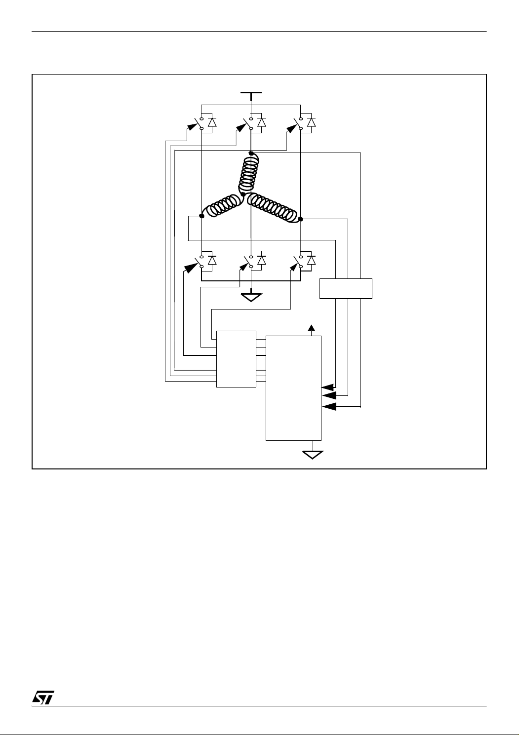
PWM MANAGEMENT FOR 3-PHASE BLDC MOTOR DRIVES USING THE ST7MC
Figure 1. ST7FMC Microcontroller with a three-phase bridge
HV
T0
T3
D0 D2 D4
T2
M
A
D3
T5
Level
shifter
B
D5
Low
Side
outputs
High
Side
outputs
T4
T1
C
5V
Rotor
position
inputs
D1
Feedback
ST7FMC
1 MOTOR CONTROL MACROCELL INTRODUCTION
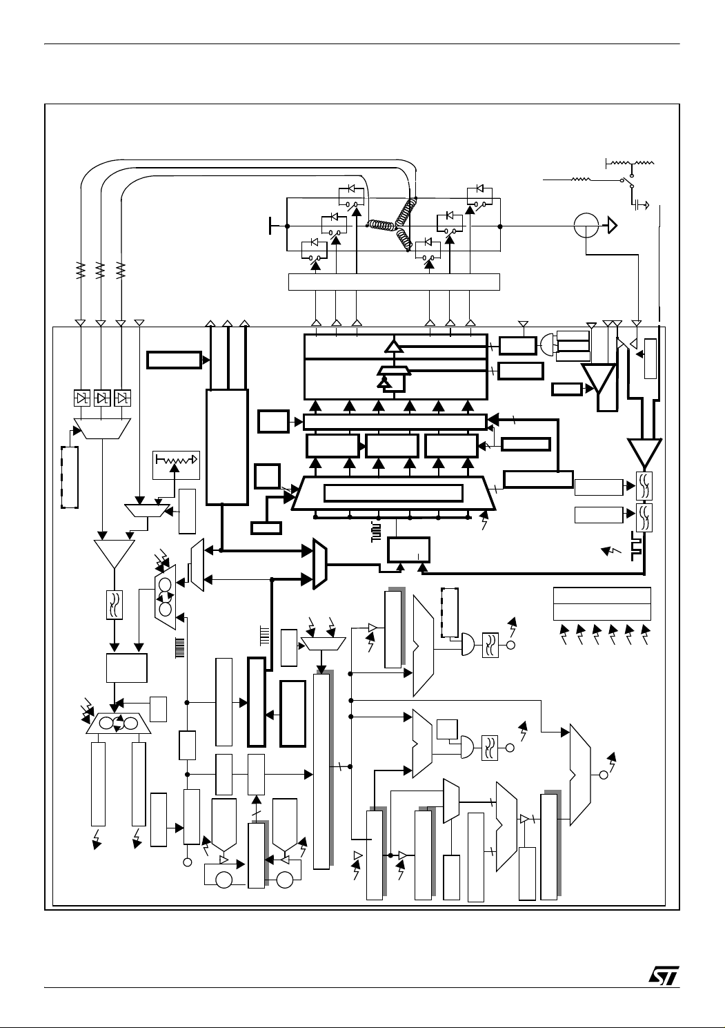
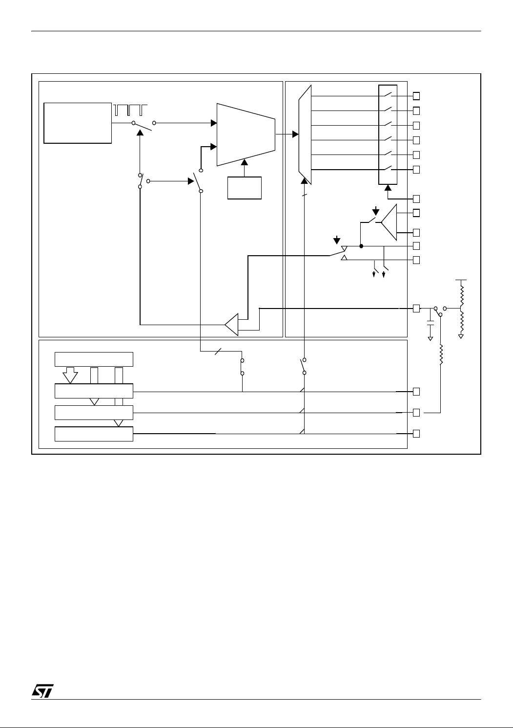
Figure 2 below gives a detailed view of the motor control macrocell included in the ST7MC mi-
crocontroller. In bold are the parts of the macrocell that are going to be described in this application note and that have a role in the PWM management. The purpose of this document is to
ease the understanding of the PWM management with the ST7MC to control a brushless 3phase DC motor and to make this explanation easier, the schematic on the figure below can
be taken as a reference of a global view of the mechanism. Besides the drawings of the func
tionalities, the names of the registers involved and often even the bits are written in this schematic. Anyhow, each time a register is discussed in this document, either a reference or an
exact description will be made for that register.
3/39
-
Page 4
PWM MANAGEMENT FOR 3-PHASE BLDC MOTOR DRIVES USING THE ST7MC
Figure 2. Detailed view of the MTC for PM BLDC motor control
DD
Board + Motor
MCPWMU/V/W
HV
C
B
A
drivers
MCIC
MCIA
MCIB
MCVREF
MPWME Reg
MCPWMU
MCPWMV
MCPWMW
MCO0
MCO2
MCO4
MCO1
MCO3
MCO5
NMCES
MOE bit
1
6
MPOL Reg
x6 x6
V
A
OAN
OAP
OCV bit
CLI bit
CLIM bit
-
+
OAON
1ext
2ext
R
R
(I)
(V)
ext
C
MCCFI0
MCCREF
OAZ(MCCFI1)
CFAV bit
bit
IS
Reg
MREF
bits
n
n
12-bit PWM generator
OS
3
Time
Dead
Ch0
Ch2
Ch1
Time
Dead
Ch3Ch4
MPHSTn Reg
High Frequency Chopper
Time
Dead
Ch5
6
2
8
6
PCN bit =0
MDTG register
MPAR Reg
-
+
CFW[2:0] bit
CFF[2:0] bit
VR2-0
REF
V
S,H
-
+
S,H
D
C
V
2
I
1
D/Z Window filter
DQ
CP
S,H
C
S,H
D
2
SPLG
1
1 /20
1 / 4
F
PRESCALER
mtc
1 / 2
+
R
MTIM
= FFh?
+1
periph
F
Z event generation
D event generation
H
Z
XT16:XT8 bit
H
D
Microcontroller
Compare U
1/128
➘
1
Ratio
1 / 2
4
ST3-0 bits
SR bit
MZREG
Z
SWA bit
SA3-0 &
OT1-0 bits
-
< 55h?
-1
S,H
D
SQ
V
R
CLI
I
]
n
H
C
1
0
H
MDREG Reg [D
D
bit
n
SDM
Compare
S
D
Filter / C
DWF[3:0]
CL
MIMR Reg
MISR Reg
S,H
-/+
R
S,H
S,H
C
D
Z
E
clr
n
bit
SZ
8
Compare
ck
nn-1
MTIM [8-bit Up Counter]
R
]
n
MZREG Reg [Z
H
Z
]
n-1
MZPRV Reg [Z
S,H
Z
DCB bit
Filter / D
ZWF[3:0]
S
Z
S,H
C
8
]
n+1
8
MWGHT Reg [a
8
A x B / 256
SWA bit
Compare
]
n+1
MCOMP Reg [C
4/39
Page 5

PWM MANAGEMENT FOR 3-PHASE BLDC MOTOR DRIVES USING THE ST7MC
2 SIX-STEP, 120° DRIVE AND PWM POWER CONTROL
To control a BLDC motor with the best efficiency, we have to know the rotor position at all
times. To achieve this there are two modes. One is called the sensor mode, where the infor
mation read back from the motor is the one coming from Hall Effect sensors (1 per phase).
The other one is the sensorless mode, where the Back Electromotive Force (BEMF) signal in
formation is the one read back from the motor. The strength of the ST7FMC is that it is compatible with all the modes to control a BLDC motor, whether it is sensorless or not and it is
even suitable with different variations within the sensorless or sensor modes which will be de
tailed later on in this application note.
In sensorless mode, in order to be able to read the BEMF information, the phase switching has
to include a dead time during which no current flows in one of the motor windings.
As shown in Figure 4, in six-step, 120° drive, power is removed from each winding every three
steps. During this dead-time phase, it is possible to detect the BEMF zero-crossing event on
this non powered winding (see
In order to control the speed, the torque or the power applied to the motor, a PWM signal is
usually logically ANDed with the switch control signals. This control is implemented by modi
fying the duty cycle of this logically ANDed PWM signal.
Figure 3 for an example).
-
-
-
-
With this method, the BEMF voltage is referred to point M of the motor and not to ground. Because this point is at high voltage, the microcontroller cannot read its value directly.
Note: In sensor mode the six-step drive or the sinusoidal drive can be implemented as the
feedback signal comes independently from the Hall Effect sensor in the dedicated input of the
microcontroller. However, in six-step drive, the method will be exactly the same as the one de
tailed for the sensorless mode. For the sensor sinusoidal mode, the PWM management is the
same as for the AC induction motor drive.
-
5/39
Page 6

PWM MANAGEMENT FOR 3-PHASE BLDC MOTOR DRIVES USING THE ST7MC
Figure 3. Reading the BEMF (Step Σ4)
HV
T0
D0 D2 D4
T2
T4
B
Read BEMF
on phase C
T3
M
B
E
A
D3
T5
M
F
D5
T1
C
D1
Figure 4. Six-step, 120° drive: control signal on the transistor gate
Σ
Step
Switch
T0
T1
1Σ2Σ3Σ4Σ5Σ6Σ1Σ2Σ3
ON
OFF
ON
OFF
ON
T2
OFF
ON
T3
OFF
ON
T4
OFF
ON
T5
OFF
Node
HV
A
0
HV
B
0
HV
C
0
BEMF Voltage
Note: voltages are represented without any PWM or demagnetization effect.
6/39
Page 7

PWM MANAGEMENT FOR 3-PHASE BLDC MOTOR DRIVES USING THE ST7MC
3 SENSORLESS CONTROL METHODS
In order to make the BEMF signal readable by the microcontroller and to detect the zerocrossing voltage of this signal, there are two main methods which we will call the classic
method for the first one and the ST method for the second. The ST7FMC microcontroller is
suitable for both methods. Each method is declinable in sub-method and the ST7MC allows
complete flexibility on which sub-method to use. Please refer to the Application Note AN1946
for a complete view and details on all the methods as this document briefly covers only the 2
main methods.
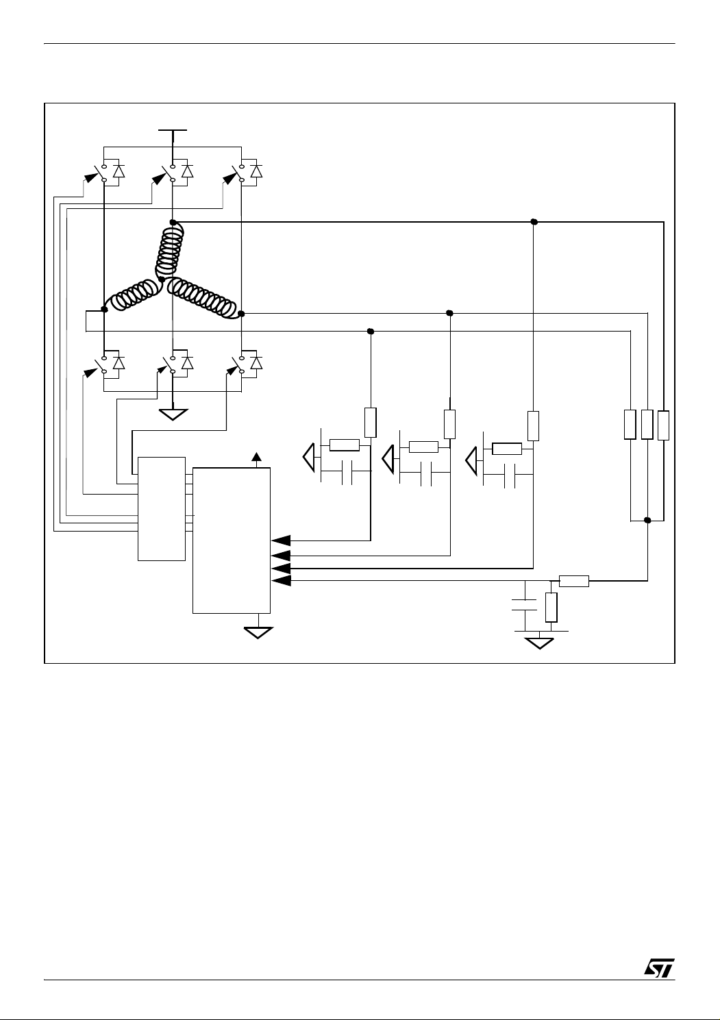
3.1 CLASSIC METHOD
The classic method involves dividing and filtering the signal coming from the non-powered
phase to make it readable by the 5V microcontroller as shown in
built and is used as the voltage reference to detect the zero-crossing event of the BEMF
signal. With this method, the PWM signal which is logically ANDed with the switch control
signal can be applied either on the high or on the low side switches as explained in the next
section. The ST7MC is able to detect the BEMF zero-crossing signal during either the PWM
signal ON time or OFF time.
Figure 5. A virtual ground is
7/39
Page 8
PWM MANAGEMENT FOR 3-PHASE BLDC MOTOR DRIVES USING THE ST7MC
Figure 5. Classic sensorless control method
HV
T0
T3
D0 D2 D4
T2
M
A
D3
T5
Level
shifter
B
D5
Low
Side
outputs
High
Side
outputs
ST7FMC
T4
T1
C
5V
Rotor
position
inputs
internal
Vref
D1
External
Vref
Virtual
ground
Note: The digital filter of ST7MC allows use of the classical method wiring without an analog
filter. In that case we can remove the virtual neutral network and replace this by just a voltage
divider on the High VOLTAGE BUS. In this situation, sampling at PWM "OFF" is possible only
for PWM applied on the high side switch. Please refer to Application Note AN1946 for more
details on this method.
8/39
Page 9
PWM MANAGEMENT FOR 3-PHASE BLDC MOTOR DRIVES USING THE ST7MC
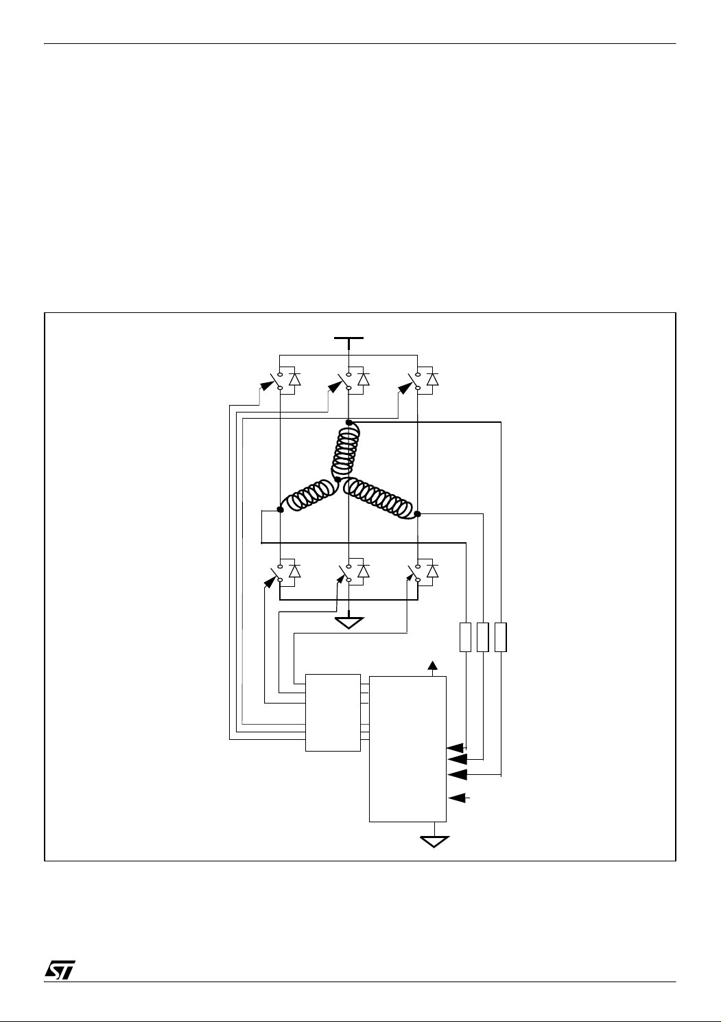
3.2 ST METHOD
With the ST Method, by using the free-wheeling diodes during the OFF time of the PWM
signal, the M potential is put to ground and the ST7MC microcontroller samples the BEMF
signal voltage during the OFF time of the PWM signal. This involves the fact that the PWM has
to be applied on the high side and that an OFF time is needed as explained in the next section
of this application note. However, fewer external components are required as it is no longer
necessary to divide and filter the signal coming from the non-powered winding. As shown in
Figure 6, only 3 external resistors are needed to limit the current input in the microcontroller
pins.
Figure 6. ST sensorless control Method
HV
T0
T3
D0 D2 D4
T2
M
A
D3
T5
Level
Shifter
B
D5
Low
Side
outputs
High
Side
outputs
ST7FMC
T4
T1
C
5V
Rotor
position
inputs
internal
Vref
D1
External
Vref
9/39
Page 10

PWM MANAGEMENT FOR 3-PHASE BLDC MOTOR DRIVES USING THE ST7MC
4 PWM MANAGER IN VOLTAGE MODE AND CURRENT MODE
The PWM signal logically ANDed with the switch control signal is used to control the power applied to the motor. It can either control the voltage on the motor with a fixed PWM duty cycle
or the current by means of an integrated current control circuitry.
When the PWM signal controls the voltage, the motor is driven in voltage mode. When it is
controlling the current, the motor is driven in current mode.
Voltage mode allows you to control the speed easily by changing the motor reference voltage.
It does not give you fine control of the current but you can limit the current and consequently
the torque to a maximum value. The voltage control is done by the PWM duty cycle.
Current mode allows you to permanently control the torque by changing the motor reference
current, because torque is proportional to current. The current in the windings is regulated in
real time and there is a true DC current flowing through the DC Bus. Current mode also allows
the current for each of the 6 steps to be finely controlled as the current control is done during
the PWM cycle.
Depending on whether the motor is driven in current or voltage mode, the PWM signal does
not have the same origin as shown in
Figure 7.
10/39
Page 11
PWM MANAGEMENT FOR 3-PHASE BLDC MOTOR DRIVES USING THE ST7MC
Figure 7. The PWM manager
MEASUREMENT
WINDOW
GENERATOR
PWM MANAGER
12-bit counter
(I)
(V)
Phase U
(I)
CURRENT
VOLTAGE
(V)
MODE
1
(V)
PCN bit
PHASE
U, V, W
Phases
CFAV bit
OAON bit
+
-
ADC
CHANNEL
MANAGER
12-bit THREE-PHASE
PWM GENERATOR
MCO5
MCO4
MCO3
MCO2
MCO1
MCO0
NMCES
OAP
OAN
OAZ(MCCFI1)
MCCFI0
MCCREF
C
(V)
(I)
V
DD
R
1
R
2
R
3
Phase U
Phase V
Phase W
MCPWMU
MCPWMV
MCPWMW
The PWM manager manages two different integral parts of the way the ST7MC drives the
motor:
– Current regulation or limitation
– Generation of the PWM signal applied on the switches
The PWM manager has two distinct motor driving modes: voltage mode and current mode. In
both cases, the motor control 12-bit timer peripheral has an essential role.
In Figure 7, the PWM manager uses the paths indicated by the (I) symbol for current mode
and by the (V) symbol for voltage mode.
11/39
Page 12
PWM MANAGEMENT FOR 3-PHASE BLDC MOTOR DRIVES USING THE ST7MC
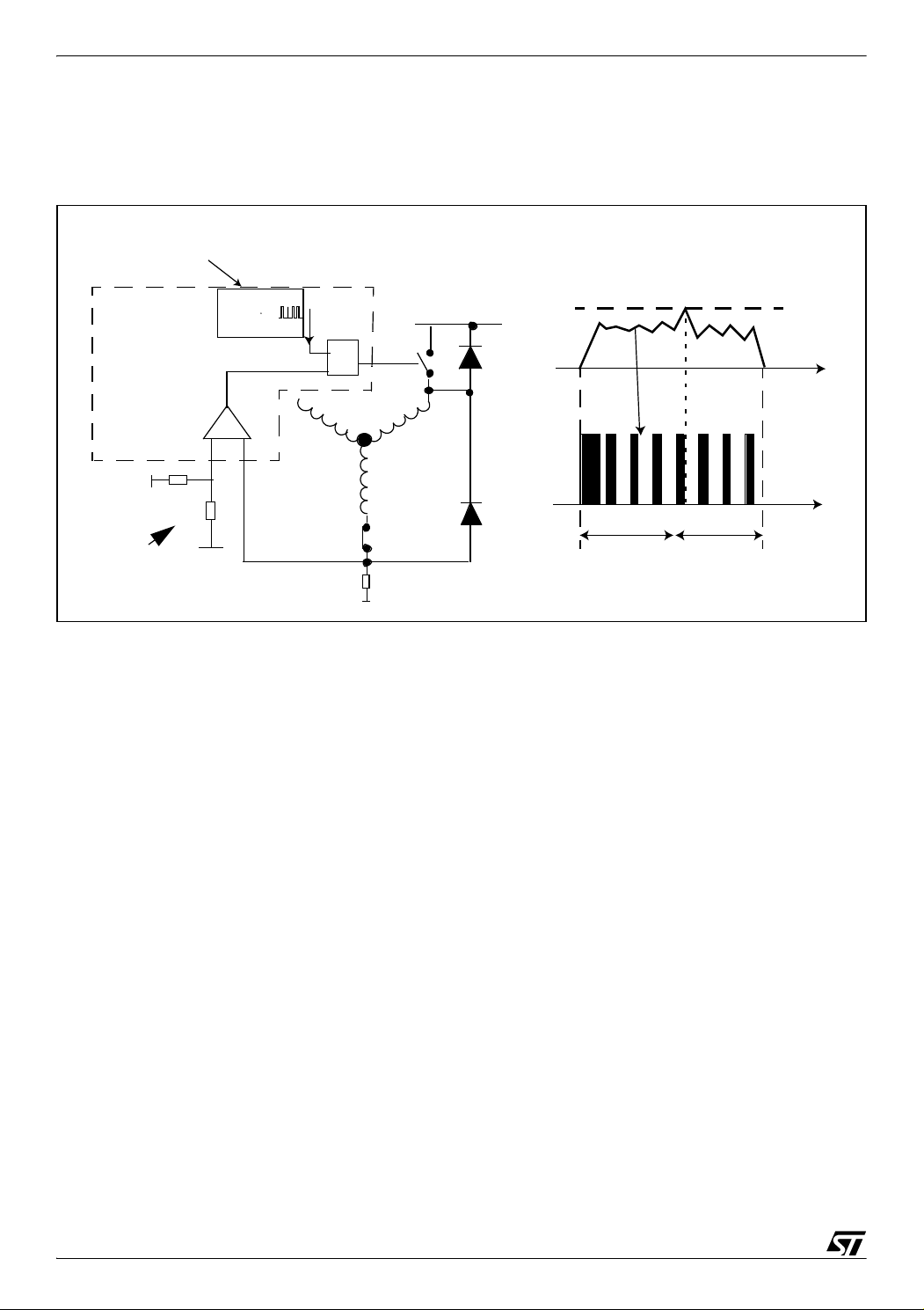
4.1 PWM MANAGER IN VOLTAGE MODE
4.1.1 Description
Figure 8. Current limitation in voltage mode control
ST7MC
PWM U output
Max current
ST7MC
Microcontroller
TIMER
set
R
HV
T1
reference
I
t
A
Motor
Voltage
step time step time
T1-T4
T1-T6
VR02139M
t
Vdd
Rext
Rext
Max current
reference
-
+
T4
In voltage mode, the PWM of the 12-bit timer (through the compare U register) gives the
voltage which is supplied to the motor, it is the voltage control of the motor. This PWM signal
is the one logically ANDed with the control switches signal in order to be able to detect the
zero-crossing and demagnetization events.
In voltage control mode, we can set a limitation to the current. The current limitation can be set
by the user with an external resistor divider as shown in
Figure 7 (R1 and R2) and Figure 8
(Rext). Usually this current limitation is the one given by the motor manufacturer. When the
current feedback reaches the maximum reference current at the comparator input, the tran
sistor to which the PWM is applied is put in off state until the current feedback becomes less
than the maximum current limit. So, one of the inputs of the internal comparator is the max
imum current limitation, the other input is the current feedback from the motor (MCCFI0 pin or
the output of the internal operational amplifier if used as shown in
Figure 7).
-
-
This current limitation is for protection and should normally never be reached when running
the motor correctly.
Figure 9 is a capture made with an oscilloscope of the different signals in Voltage mode:
We can see that the current feedback from the motor never reaches the current limitation and
the increase and decrease of the current in the motor corresponds to the PWM signal on the
waveform 2.
12/39
Page 13

PWM MANAGEMENT FOR 3-PHASE BLDC MOTOR DRIVES USING THE ST7MC
Figure 9. Oscilloscope waveforms: Voltage Mode
1. Current in Phase A
2. Signal on High Side
Switch of Phase A on
Triple Half Bridge
Configuration
3. Current Limitation
3. Current Limitation
4. Current Feedback
Note: In speed regulation, the PWM duty cycle value only needs to be correct when starting
the motor. Once the target speed is reached, the PWM duty cycle will be adjusted automati
cally by the ST7MC.
-
4.1.2 PWM signal register setting in Voltage mode
In voltage mode, the 12-bit timer is used to set the PWM signal.
Compare 0 registers:
The compare 0 high and low registers are for setting the frequency of the PWM.
COMPARE 0 PRELOAD REGISTER HIGH (MCP0H)
Read/Write (except bits 7:4)
Reset Value: 0000 1111 (0Fh)
7 0
- - - - CP0H3 CP0H2 CP0H1 CP0H0
Bits 7:4 = Reserved.
Bits 3:0 = CP0H[3:0] Most Significant Bits of Compare 0 preload value.
COMPARE 0 PRELOAD REGISTER LOW (MCP0L)
Read/Write
Reset Value: 1111 1111 (FFh)
7 0
CP0L7 CP0L6 CP0L5 CP0L4 CP0L3 CP0L2 CP0L1 CP0L0
Bits 7:0 = CP0L[7:0] Low byte of Compare 0 preload value.
13/39
Page 14

PWM MANAGEMENT FOR 3-PHASE BLDC MOTOR DRIVES USING THE ST7MC
Compare U registers:
The compare U high and low registers are for setting the duty cycle of the PWM signal in
voltage mode.
COMPARE PHASE U PRELOAD REGISTER HIGH (MCPUH)
Read/Write
Reset Value: 0000 0000 (00h)
7 0
CPUH7 CPUH6 CPUH5 CPUH4 CPUH3 CPUH2 CPUH1 CPUH0
Bits 7:0 = CPUH[7:0] Most Significant Byte of phase U preload value
COMPARE PHASE U PRELOAD REGISTER LOW (MCPUL)
Read/Write Read/Write (except bits 2:0)
Reset Value: 0000 0000 (00h)
7 0
CPUL7 CPUL6 CPUL5 CPUL4 CPUL3 - - -
Bits 7:5 = CPUL[7:3] Low bits of phase U preload value.
Bits 2:0 = Reserved.
4.2 PWM MANAGER IN CURRENT MODE CONTROL
4.2.1 Description
Figure 10. Current regulation in current mode control
ST7MC
Microcontroller
TIMER
12-bit internal timer
PWM output
clock
- +
set
R
T4
A
T1
HV
current
reference
clock
Motor
Voltage
I
step time
T1-T4
t
t
t
step time
T1-T6
VR02139N
14/39
Page 15

PWM MANAGEMENT FOR 3-PHASE BLDC MOTOR DRIVES USING THE ST7MC
In current mode, the PWM output by the 12-bit timer (either MCPWMU, V or W) represents the
reference current to be applied to the motor. The PWM duty cycle is the current level at which
we want to polarise the motor. At 100% duty cycle, the signal output is at 5V, this corresponds
to the maximum current to be applied to the motor for maximum torque. The PWM duty cycle
is obtained by dividing the reference current we want in the motor (depending on the torque
needed) by the maximum current. For example, if the maximum current is 1A and if the refer
ence current has to be 0.2A, the PWM duty cycle will be 20%.
An external resistor and capacitor are added as shown in Figure 7 (R3) and Figure 10 in order
to generate the reference current based on a digital to analog converter (DAC) of the PWM
signal.
So, for the internal comparator, one of the inputs is the current feedback of the motor (MCCFI0
pin or the output of the internal operational amplifier if used), the other input is the reference
current given by the filtered PWM signal from the 12-bit timer.
We see in Figure 7 and Figure 10 that the internal clock is used in current mode control. The
internal clock outputs a PWM signal as well. The frequency of this signal is user-selectable
from several values from 390Hz to 50KHz through 4 bits and the off-time of this signal is also
user-selectable (from 2.5µs to 40µs) with a minimum value of 2.5µs needed to allow the sta
bilization of the system if the ST method is used to allow the sampling of the back-EMF signal
during off-time. The PWM signal frequency output by the clock represents the current fre
quency used to supply the motor. The off-time of this PWM signal is variable, with a lower limit
of 2.5µs in the sensorless mode ST method. The PWM signal output by the internal clock is
applied to the designated switch. This mechanism has the following procedure as shown in
Figure 10:
-
-
-
When the current feedback from the motor reaches the reference current given by the 12-bit
timer PWM signal at the comparator input, the internal clock signal is reset. The switch where
the PWM is applied is put in an OFF state until the current feedback is lower than the refer
ence current as shown in Figure 10. That’s why the duty cycle of the internal clock is variable.
A minimum off-time has to be defined by the software programmer in sensorless ST method
but the duty cycle is modified depending on the motor behaviour.
Figure 11 is a capture done with an oscilloscope of the different signals in Current mode.
We can see that as soon as the current back from the motor reaches the level of the current
limitation, the PWM signal on waveform 2, meaning the PWM signal on the high side switch of
the corresponding phase is put off.
15/39
-
Page 16

PWM MANAGEMENT FOR 3-PHASE BLDC MOTOR DRIVES USING THE ST7MC
Figure 11. Oscilloscope waveforms: Current Mode
1. Current in Phase A
2. Signal on High Side
Switch of Phase A on
Triple Half Bridge
Configuration
3. Current Regulation
Signal through PWM
Compare U filtered
4. Current Feedback
Note: In speed regulation, the 12-bit timer PWM duty cycle only has to have the right value to
start the motor. Once the target speed is reached, the PWM duty cycle will be adjusted auto
matically by the ST7MC.
4.2.2 PWM signal register setting in Current mode
In current mode, a combination of an internal clock and the output of the current comparator is
used to set the PWM signal, the registers described below are the ones used to set the fre
quency and the minimum OFF time if needed from the PWM signal for the internal clock.
PRESCALER & SAMPLING REGISTER (MPRSR)
Read/Write
Reset Value: 0000 0000 (00h)
7 6 5 4 3 2 1 0
SA3 SA2 SA1 SA0 X X X X
Bits 7:4 = SA[3:0]: Sampling Ratio.
These bits contain the sampling ratio value for current mode. This sets the frequency of the
PWM according to the following table
-
-
16/39
Page 17

PWM MANAGEMENT FOR 3-PHASE BLDC MOTOR DRIVES USING THE ST7MC
Table 1. Frequency selection
SA3 SA2 SA1 SA0 Sampling Frequency
0 0 0 0 50.0 KHz
0 0 0 1 40.0 KHz
0 0 1 0 33.33 KHz
0 0 1 1 25.0 KHz
0 1 0 0 20.0 KHz
0 1 0 1 18.1 KHz
0 1 1 0 15.4 KHz
0 1 1 1 12.5 KHz
1 0 0 0 10 KHz
1 0 0 1 6.25 KHz
1 0 1 0 3.13 KHz
1 0 1 1 1.56 KHz
1 1 0 0 1.25 KHz
1 1 0 1 961 Hz
1 1 1 0 625 Hz
1 1 1 1 390 Hz
PWM REGISTER (MPWME)
Read/Write
Reset Value: 0000 0000 (00h)
7 6 5 4 3 2 1 0
X PWMW PWMV PWMU OT3 OT2 OT1 OT0
The current reference is provided to the comparator by Phase U, V or W of the PWM Generator (up to 12-bit accuracy) and the signal from the three compare registers U, V or W can be
output by setting the PWMU, PWMV or PWMW bits.
Bits 3:0 = OT[3:0]: Off Time selection
These bits are used to select the OFF time in sensorless current mode as shown in the following table
17/39
Page 18

PWM MANAGEMENT FOR 3-PHASE BLDC MOTOR DRIVES USING THE ST7MC
Table 2. off time table
Off Time sensorless
OT3 OT2 OT1 OT0
0 0 0 0 2.5 µs
0 0 0 1 5 µs
0 0 1 0 7.5 µs
0 0 1 1 10 µs
0 1 0 0 12.5 µs
0 1 0 1 15 µs
0 1 1 0 17.5 µs
0 1 1 1 20 µs
1 0 0 0 22.5 µs
1 0 0 1 25 µs
1 0 1 0 27.5 µs
1 0 1 1 30 µs
1 1 0 0 32.5 µs
1 1 0 1 35 µs
1 1 1 0 37.5 µs
1 1 1 1 40 µs
mode (SR=0)
(DS[3:0]=0)
Sensor Mode (SR=1) or sampling
during ON time in sensorless
(SPLG =1 and/or DS[3:0] bits)
No minimum off time
4.3 SUMMARY VOLTAGE/CURRENT MODE
In voltage mode, the 12-bit timer PWM signal (compare U register) gives the voltage to be applied to the motor. This PWM signal is applied to the switches. The internal clock is not used
in this mode.
A current limitation is implemented in voltage mode. The current limitation can be set by an external divider resistor or by an other PWM signal filtered.
In current mode, the 12-bit timer PWM signal gives the reference current to be applied to the
motor. This signal has to be filtered by an external RC. The internal clock is used and the
PWM signal from the internal clock is applied to the switches.
In current mode, the current is regulated by comparing the reference current and the feedback
current from the motor.
18/39
Page 19

PWM MANAGEMENT FOR 3-PHASE BLDC MOTOR DRIVES USING THE ST7MC
5 MANAGEMENT OF PWM AND READING OF BEMF
Depending on the control method used to drive the motor, the PWM signal to detect the BEMF
zero voltage crossing signal can be applied in 2 ways:
– On the high side: During the step, the PWM is applied only on the high side switch, the low
side is ON during the complete step.
– On the low side: During the step, the PWM is applied only on the low side switch, the high
side is ON during the complete step.
In the ST7MC device, OE [5:0] bits in the MPAR register are used to define whether the corresponding outputs are in high or low side switch position. Then OO [5:0] bits in MPHST register define if the channel is active or not and finally OS [2:0] bits in MCRB register distribute
the PWM on the active channels high or low side. Please refer to the product datasheet for the
motor control device in the channel manager section for more details or to
complete configuration.
Figure 12. Current during PWM ON time
HV
Section 6 to see a
T0
T3
The 2 switches T2 and T3 are ON
D0 D2 D4
T2
HV
A
2
D3
T5
T4
B
M
C
D5
T1
D1
5.1 PWM ON THE HIGH SIDE
When the related switches are ON, the current passes through the two switches and two
motor windings (these are switches T2 and T3 in the example in
Figure 12).
The potential at point M is HV/2. If nothing is done, the BEMF can not be read by the ST7MC
because the voltage is too high to be read by the microcontroller.
Using the classic method, the BEMF is divided and filtered as is the rebuilt virtual ground and
so the BEMF zero-crossing event can be read when the PWM is ON on the high side switch.
19/39
Page 20

PWM MANAGEMENT FOR 3-PHASE BLDC MOTOR DRIVES USING THE ST7MC
When the PWM signal is ON when using the Classic method, the voltage at the virtual ground
will be HV/2 divided and filtered and the voltage at point C will be (HV/2 + BEMF) divided and
filtered so the comparison can be done by the comparator in the microcontroller as it will stay
within the microcontroller supply voltage range (0 - Vdd) after division and filtering.
When the high side switch PWM is OFF, the current inside the motor continues to flow in the
same direction (
Figure 13). While the switch is off, the current can only use the diode (D5 in
our example).
In this case the potential in A is the Von of the T3 switch, the potential in B is -Vf of D5 and the
potential at M is (Von-Vf)/2. It is close to zero because in most cases Von = Vf.
In this case the microcontroller can read the complete BEMF voltage referred to the ground
terminal on the phase C.
This is the configuration used for the ST method where the sampling of the BEMF signal is
only done during the Off time of the PWM signal. No dividers nor filters are needed externally
as we are looking at a signal that is close to the MCU ground level.
Note: This sampling method of the BEMF signal is also appropriate for the classic method. In
fact the sampling of the BEMF can be done either during ON or OFF time of the PWM for the
classic method.
Figure 13. PWM on high side: Current during OFF time
HV
B
D5
Free-wheeling
diode: D5
T4
C
T1
T0
T3
PWM on T2
T2
D0 D2 D4
PWM
M
A
0V
D3
T5
current during OFF TIME
D1
20/39
Page 21

PWM MANAGEMENT FOR 3-PHASE BLDC MOTOR DRIVES USING THE ST7MC
5.2 PWM ON THE LOW SIDE
When the related switches are ON (example of Figure 12) the current passes through the two
switches and two motor windings.
When the low side is switched OFF, the current inside the motor continues to flow in the same
direction (
Figure 14). While the switch is OFF, the current can only use the diode (D0 in our ex-
ample).
In this case the potential at A is (HV+Vf), the potential at B is (HV-Von) and the potential at M
is (2xHV+Von-Vf)/2. We can consider it to be HV (because in most cases Von = Vf).
In this case the microcontroller can read the BEMF voltage only if the Classic method is used
during ON time of the PWM signal because the signal in C is divided and filtered before the mi
crocontroller input pin. Considering the ST method, the sampling of the BEMF is done only
during the OFF time of the PWM and as with the ST method, the signal is not divided and fil
tered in C before the microcontroller pin, this method can not be used as the voltage in C is
close to HV during the PWM off time.
– Von is the voltage of the switch when it is turned ON
-
-
– Vf is the forward voltage of a diode
Figure 14. PWM on low side: Current during OFF time
HV
T0
T3
PWM
PWM on T3; Free-wheeling diode D0
D0 D2 D4
T2
HV
A
D3
T5
T4
B
M
D5
T1
C
D1
21/39
Page 22

PWM MANAGEMENT FOR 3-PHASE BLDC MOTOR DRIVES USING THE ST7MC
5.3 EXAMPLE OF CONFIGURATION OF THE ST7MC REGISTERS
As explained in section 2 “Sensorless control methods”, we have described 2 main sensorless
control methods which the ST7MC is compatible with. Please refer to AN1946 for more de
tails. The steps to correctly configure the ST7MC registers depending on the sensorless control method used are as follows:
– Generate a Pulse Width Modulation signal. If the ST sensorless control method is used, then
a 2.5µs minimum off time is needed to read the BEMF voltage during the off time (useless in
Classic method detection).
In Voltage mode (the VOC1 bit is reset in the MCRA register), when driving a PM BLDC motor
(the PCN bit is reset in the MDTG register) in six-step drive, a single PWM signal is used to
supply the input stage. This PWM signal which is applied to the switches is generated using
the 12-bit PWM counter for frequency and the 13 bit compare U register for duty cycle
(MCPUL:MCPUH registers).
In Current mode (VOC1 bit is set in the MCRA register), the PWM output signal is generated
by a combination of the output of the measurement window generator and the output of the
current comparator and is directed to the output channel manager as well. This can be done
by setting the PWM frequency through SA[3:0] bits in the MPRSR register and the minimum
off time using the OT[3:0] bits in the MPWME register. The off time is also dependent on the
output of the current comparator as explained in
Section 4 of this document.
-
– Apply this PWM on the high side or low side switches depending on the sensorless control
method used. To do so, you have to configure the microcontroller with the right configuration.
In order to configure correctly the registers, this sequence has to be followed.
– Split the switches in two parts by means of the high side/low side configuration. This is done
using the OE [5:0] bits in the MPAR register.
PARITY REGISTER (MPAR)
Read/Write
Reset Value: 0000 0000 (00h)
7 6 5 4 3 2 1 0
X X OE5 OE4 OE3 OE2 OE1 OE0
Bits 5:0 = OE[5:0]: Output Parity Mode.
0: Output channel is High
1: Output channel Low
For example: T1, T3, T5 low side and T0, T2, T4 high side.
22/39
Page 23

PWM MANAGEMENT FOR 3-PHASE BLDC MOTOR DRIVES USING THE ST7MC
– Select the group you want to read the BEMF from by programming the REO bit in the MPOL
register. The group the BEMF is read from depends on the sensorless control method used.
If the ST method is used, the high side group has to be selected because the PWM has to
be applied on the high side as seen in the previous chapter, therefore, the BEMF can be read
only from the high side group, REO bit is reset. If the classic method is used, the BEMF can
be read either from the high side group or from the low side group, it depends on where the
PWM signal will be applied as described below. So in this configuration, the REO bit can be
set or reset. Select also the polarity of the output channel through the MPOL register.
POLARITY REGISTER (MPOL)
Read/Write (some bits write-once)
Reset Value: 0011 1111 (3Fh)
7 6 5 4 3 2 1 0
ZVD REO OP5 OP4 OP3 OP2 OP1 OP0
Bit 7 = ZVD: Z vs D edge polarity.
0: Zero-crossing and End of Demagnetization have opposite edges
1: Zero-crossing and End of Demagnetization have same edge
Bit 6 = REO: Read on High or Low channel bit
0: Read the BEMF signal on High channels
1: Read on Low channels
Note: This bit always has to be configured whatever the sampling method.
Bits 5:0 = OP[5:0]: Output channel polarity.
These bits are used together with the OO[5:0] bits in the MPHST register to control the output
channels.
0: Output channel is Active Low
1: Output channel is Active High.
– Select the PWM direction after Demagnetization (D) event just before the Zero-crossing (Z)
event. The demagnetization event and the corresponding PWM configuration will be ex
plained in Section 5. So the PWM direction can be selected using the OS1 bit in MCRB register. The same is true for the group to read the BEMF from, the PWM can be applied
differently depending on the sensorless control method used. If the ST method is used, then
the PWM signal has to be applied on the high side, which means that the OS1 bit is reset in
MCRB register. If the classic sensorless control method is used, then the PWM signal can
be applied either on the high side or on the low side. In both cases, the microcontroller is able
23/39
Page 24

PWM MANAGEMENT FOR 3-PHASE BLDC MOTOR DRIVES USING THE ST7MC
to detect the BEMF. So, in that case OS1 bit can be set or reset. It depends mainly on the
application and on the user.
MPHST register bits OO[5:0] are used to put the corresponding output channel active or not.
This has to be configured each step over the repetition of the six steps.
PHASE STATE REGISTER (MPHST)
Read/Write
Reset Value: 0000 0000 (00h)
7 6 5 4 3 2 1 0
X X OO5* OO4* OO3* OO2* OO1* OO0*
Bits 5:0 =OO[5:0]*: Channel On/Off bits
These bits are used to switch channels on/off at the next commutation
0: Channel Off, the relevant switch is OFF, no PWM possible
1: Channel On the relevant switch is ON, PWM is possible
OO[5:0] Bit Meaning
OO[5:0] Output Channel State
0 Inactive
1 Active
* = Preload bits, new value taken into account at next C event
In addition to the PWM configuration flexibility, the ST7MC microcontroller features a dead
time generator embedded in the motor control peripheral. This is used mainly for the genera
tion of the 3 sinewave 120° shifts for the drive of an AC induction 3-phase motor but it can be
used to perform “synchronous rectification” as explained in the next chapter when driving a
PM BLDC motor.
-
24/39
Page 25

PWM MANAGEMENT FOR 3-PHASE BLDC MOTOR DRIVES USING THE ST7MC
6 SYNCHRONOUS RECTIFICATION
6.1 SYNCHRONOUS RECTIFICATION PRINCIPLE
Whatever method is used, the classic method or the ST method, as soon as a PWM signal is
logically ANDed with the switch control signal, the free wheeling diodes of the triple half bridge
configuration are used during the off time off the PWM signal and the current continues to flow
in the same direction in the motor. The ST7MC features a dead time generator that allows ap
plication of complementary PWM on the switch adjacent to the one where PWM is applied.
With this feature, the conduction losses can be reduced. This is called the “synchronous rec
tification”.
Precautions must be taken to avoid short circuits in half bridges. This is ensured by driving
high and low side switches with complementary signals and by managing the time between
the switching-off and the switching-on instants of the adjacent switches. This time is the dead
time and has to be adjusted depending on the devices connected to the PWM outputs and
their characteristics (intrinsic delays of level-shifters, delays due to power switches,...).
-
-
-
In the ST7MC, the dead time is set on six dedicated bits in a register allowing a range of dead
times from 125ns to 16µs. When Fmtc is 16MHz. Dead time can be set with steps of 125, 250
or 500ns.
As an example on Figure 14, if the dead time generator is activated, then during the off time of
the PWM on T3, T0 will be switched-on so the current will flow through the switch and not
through the free-wheeling diode D0.
Figure 15 shows the relationship between the output signals of the deadtime register on the
adjacent switches and its inputs.
Once activated, the dead time generator generates two output signals on the adjacent
switches: A and B.
The A output signal is the same as the input phase signal except for the rising edge, which is
delayed relative to the input signal rising edge.
The B output signal is the opposite of the input phase signal except the rising edge which is
delayed relative to the input signal falling edge.
25/39
Page 26

PWM MANAGEMENT FOR 3-PHASE BLDC MOTOR DRIVES USING THE ST7MC
Figure 15. Dead times waveform
Reference
Input signal
Output A
Delay
Output B
Delay
5V
0V
5V
0V
5V
0V
Figure 16 and Figure 17 show waveforms of the signal on 2 adjacent switches during synchro-
nous rectification. Figure 17 is a zoom of Figure 16
The dead time has been set in this example to 0.75µs.
Figure 16. Oscilloscope waveform: synchronous rectification 1
1. Current Waveform in Phase A
26/39
2. signal on the high side switch
of phase A
3. signal on the adjacent switch,
the low side switch of phase A
when the synchronous
rectification is enabled and a
dead time is set
Page 27

PWM MANAGEMENT FOR 3-PHASE BLDC MOTOR DRIVES USING THE ST7MC
Figure 17. Oscilloscope waveform: synchronous rectification 2
1. Current Waveform in Phase A
2. signal on the high side switch
of phase A
3. signal on the adjacent switch,
the low side switch of phase A
when the synchronous
rectification is enabled and a
dead time is set
6.2 SYNCHRONOUS RECTIFICATION CONFIGURATION
When driving a PM BLDC motor (PCN bit is reset in MDTG register), the PWM applied to the
output channel depends if the motor is driven in voltage or current mode but the dead times
are applied in the same way regardless of the source of the PWM signal.
As soon as the dead time generator is activated (DTE bit is set in MDTG register), a complementary PWM is applied to the adjacent switch. The dead time value is set-up through the bits
DTG [5:0] in MDTG register. The range can go from 125ns to 16µs with steps of 125ns, 250ns
and 500ns when Fmtc is 16MHz.
Note: It is also possible to add a chopper on the PWM signal output using bits HFE[1:0] and
HFRQ[2:0] in the MREF register.
DEAD TIME GENERATOR REGISTER (MDTG)
Read/Write (except bits 5:0 write once-only)
Reset Value: 1111 1111 (FFh)
7 0
PCN DTE DTG5 DTG4 DTG3 DTG2 DTG1 DTG0
Bit 7 = PCN: Number of PWM Channels.
0: Only PWM U signal is output to the PWM manager for six-step mode motor control (e.g. PM
BLDC motors)
1: The three PWM signals U, V and W are output to the channel manager (e.g. for three-phase
sinewave generation)
27/39
Page 28

PWM MANAGEMENT FOR 3-PHASE BLDC MOTOR DRIVES USING THE ST7MC
Bit 6 = DTE*: Dead Time Generator Enable
0: Disable the Dead Time generator
1: Enable the Dead Time generator and apply complementary PWM signal to the adjacent
switch
Bits 5:0 = DTG[5:0]*: Dead time generator set-up.
These bits set-up the deadtime duration and resolution
* = write once-only bit if PCN bit is set, read/write if PCN bit is reset. To clear the DTE bit if
PCN=1, it is mandatory to clear the PCN bit first.
28/39
Page 29
PWM MANAGEMENT FOR 3-PHASE BLDC MOTOR DRIVES USING THE ST7MC
7 WINDING DEMAGNETIZATION
When the microcontroller switches from one step to the next, the non-powered winding needs
a certain demagnetization time. During this time, the current in the winding continues in the
same direction but decreases to zero. It is not possible to see the BEMF voltage as long as
this current is still present, because during this time the voltage on the winding is tied to 0V or
HV by the free-wheeling diode.
Due to the winding self-induction, the demagnetization time decreases if the reverse voltage
on the winding increases. We want to decrease the demagnetization time of the winding so
that the window to detect the BEMF zero voltage crossing event is wider. So the goal to de
crease this time and to accelerate the end of demagnetization event is to apply the maximum
reverse voltage on the winding that needs to be demagnetized. To do so, depending on the
previous step configuration as we are going to describe in this section, we can apply either the
PWM on the low side switch or on the high side switch to accelerate the demagnetization.
Let’s look at two examples to illustrate the two possible cases:
-
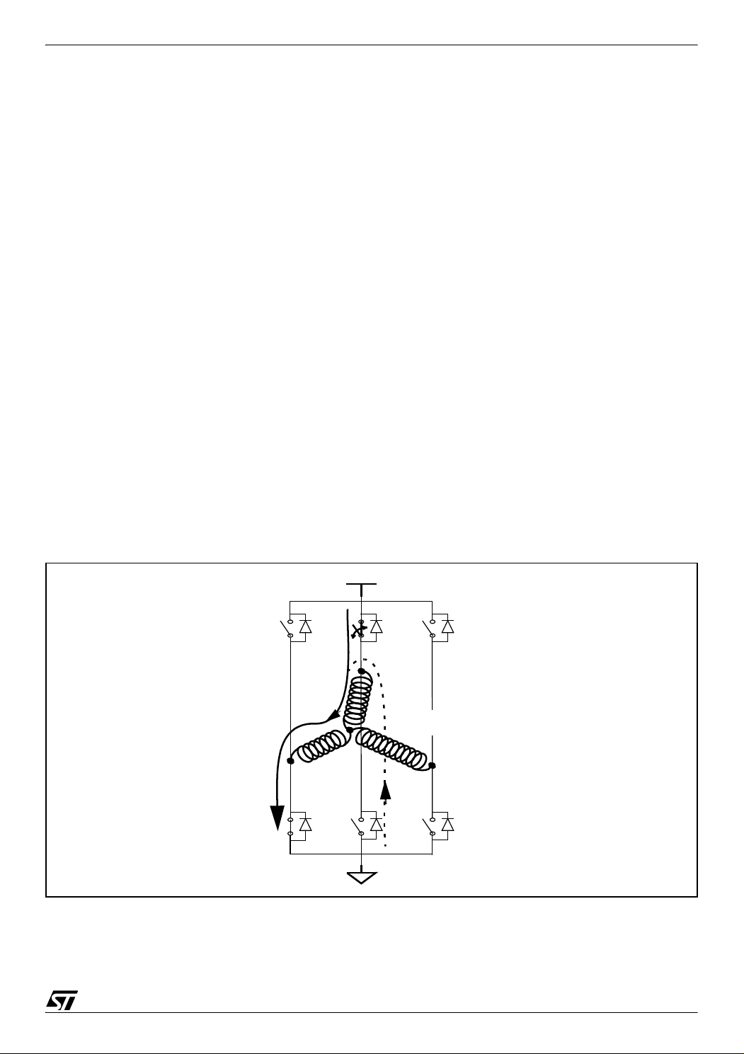
7.1 ACCELERATION OF DEMAGNETIZATION WHEN PWM IS APPLIED ON THE LOW SIDE SWITCH
Figure 18 shows step Σ4 (switches T2-T3 are ON) with the normal current and the free-
wheeling current (dotted line) during the PWM OFF time of the high side switch T2.
Figure 18. Step Σ4 (switches T2-T3 are ON)
HV
T0
T3
D0 D2 D4
T2
Normal
current
M
A
D3
T5
T4
B
free-wheeling current
for BEMF reading (ST method)
C
D5
T1
D1
29/39
Page 30

PWM MANAGEMENT FOR 3-PHASE BLDC MOTOR DRIVES USING THE ST7MC
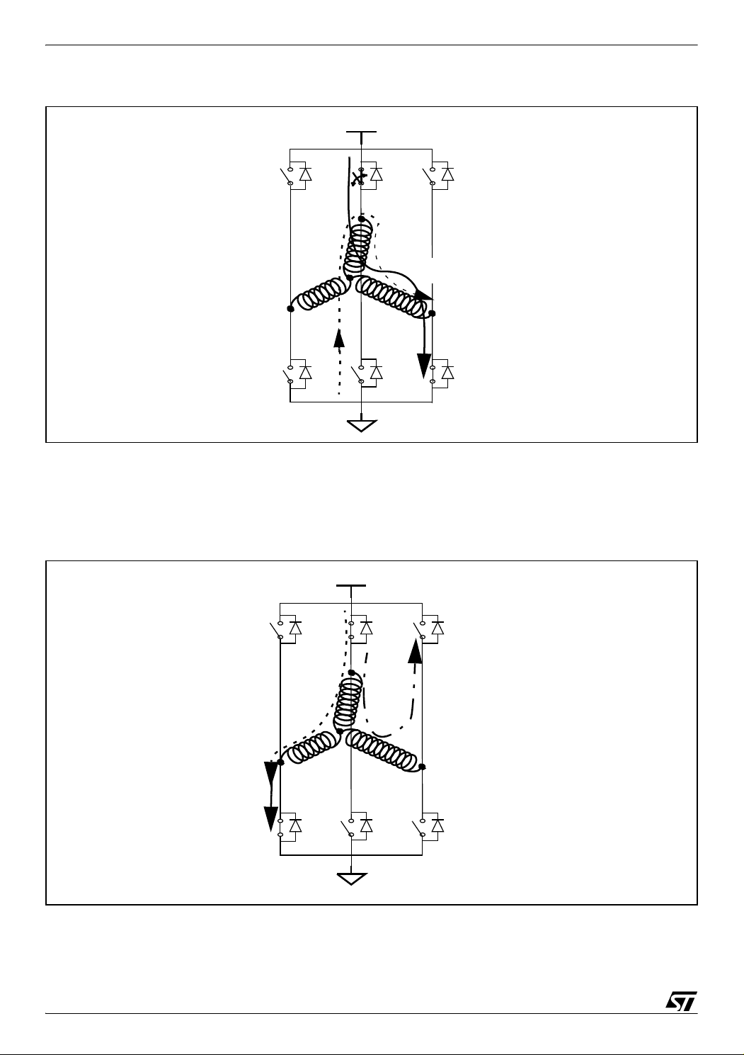
When switching from step Σ4 (switches T2-T3 are ON) to step Σ5 (switches T4-T3 are ON), a
free-wheeling, decreasing demagnetization current is still present through the B terminal
(dashed line) and an increasing magnetization current appears through the C terminal (dotted
Figure 19 shows these two currents during the PWM ON time.
line).
Figure 19. Step Σ5 (switches T4-T3 are ON) during the demagnetization PWM ON time
HV
T0
A
T3
PWM on T2
T2
D0 D2 D4
B
M
D3
T5
T4
Normal mode
magnetization
current
C
D5
T1
free wheeling
demagnetization
current
D1
F
This means, during the PWM ON time:
– The potential of B is zero
– The potential of M is close to HV/3
Now depending on the switch we are going to apply the PWM signal, the demagnetization
time of winding B will be decreased and the end of demagnetization event will be accelerated
during this PWM signal OFF time. The numerous dedicated registers in the ST7MC peripheral
allow the flexibility to choose where to apply the PWM signal between the different events. The
maximum reverse voltage to decrease the demagnetization time is achieved during the OFF
time of the PWM signal.
30/39
Page 31

PWM MANAGEMENT FOR 3-PHASE BLDC MOTOR DRIVES USING THE ST7MC
Figure 20. Acceleration of demagnetization during low side switch PWM OFF time
HV
T0
T3
PWM
D0 D2 D4
T2
A
D3
T5
T4
B
M
C
D5
T1
Demagnetization
current
Normal
current
D1
In our example, during step Σ4 (switches T2-T3 are ON), the VMB voltage on the MB winding
was positive. At the beginning of step Σ5 (switches T4-T3 are ON), the voltage on terminal B
will be tied to 0V and the shortest demagnetization configuration is the one that provides the
highest voltage at point M to apply the maximum reverse voltage and decrease the demagnet
ization time.
It is easy to verify that the highest voltage (2HV/3) is obtained when the PWM is applied only
on the low side switch T3. During the OFF time of this PWM signal (configuration shown in
Figure 20), the voltage at point M is 2HV/3. Otherwise if the PWM signal is applied on the high
side switch T4, then during the OFF time of the PWM signal, the voltage at point M is 0V. So,
in this configuration, the PWM signal has to be applied on the low side switch T3 after the com
mutation event in order to accelerate the demagnetization time during the OFF time of this
PWM signal.
-
-
7.2 ACCELERATION OF DEMAGNETIZATION WHEN PWM IS APPLIED ON THE HIGH SIDE SWITCH
Figure 21 shows step Σ3 (switches T2-T1 are ON) with the normal current and the free-
wheeling current (dotted line) during the PWM OFF time of the high side switch T2.
31/39
Page 32
PWM MANAGEMENT FOR 3-PHASE BLDC MOTOR DRIVES USING THE ST7MC
Figure 21. Step Σ3 (switches T2-T1 are ON)
HV
T0
T3
D0 D2 D4
T2
Normal
current
M
A
D3
T5
T4
B
free-wheeling current
for BEMF reading (ST method)
C
D5
T1
D1
When switching from step Σ3 (switches T2-T1 are ON) to step Σ4 (switches T2-T3 are ON), a
free-wheeling, decreasing demagnetization current is still present through the C terminal
(dashed line in
Figure 22) and an increasing magnetization current appears through the B ter-
minal (dotted line). Figure 22 shows these two currents during the PWM ON time.
Figure 22. Step Σ4 (switches T2-T3 are ON) during the demagnetization PWM ON time
HV
T0
Normal mode
magnetization
current
T3
D0 D2 D4
A
D3
PWM on T2
This means, during the PWM ON time:
– The potential of B is HV
32/39
T2
T5
T4
B
M
D5
free wheeling
demagnetization
current
C
T1
D1
Page 33

PWM MANAGEMENT FOR 3-PHASE BLDC MOTOR DRIVES USING THE ST7MC
– The potential of M is close to 2HV/3
Now depending on the switch we are going to apply the PWM signal ON, the demagnetization
time of winding C will be decreased and the end of demagnetization event will be accelerated
during this PWM signal OFF time. The goal is to apply the maximum reverse voltage on
winding C.
Figure 23. Acceleration of demagnetization during high side switch PWM off time
HV
T0
Normal mode
magnetization
current
T3
D0 D2 D4
A
D3
PWM on T2
T2
B
M
T5
T4
D5
T1
Normal
current
demagnetization
current
C
D1
In our example, during step Σ3 (switches T2-T1 are ON), the VMC voltage on the MC winding
was negative. At the beginning of step Σ4 (switches T2-T3 are ON), the voltage on terminal C
will be tied to HV and the shortest demagnetization configuration is the one that provides the
lowest voltage at point M to apply the maximum reverse voltage and decrease the demagnet
ization time.
It is easy to verify that the lowest voltage HV/3 is obtained when the PWM is applied only on
the high side switch T2. During the OFF time of this PWM signal, the voltage at point M is HV/
3 (configuration shown in
Figure 23). Otherwise if the PWM signal is applied on the low side
switch T3, then during the OFF time of the PWM, the voltage at point M is HV. So, in this configuration, the PWM signal has to be applied on the high side switch T2 after the commutation
event in order to accelerate the demagnetization time.
-
33/39
Page 34

PWM MANAGEMENT FOR 3-PHASE BLDC MOTOR DRIVES USING THE ST7MC
7.3 REGISTERS CONFIGURATION TO ACCELERATE THE DEMAGNETIZATION.
The ST7MC allows you to program different PWM configurations in sensorless mode. In
sensor mode, the demagnetization event is useless as the feedback information is not read
from the windings.
In order to minimize the demagnetization time in sensorless mode, the ST7MC allows you to
modify the PWM direction between the step commutation and the end of demagnetization.
In sensorless mode the OS2 bit in register MCRB enables the PWM on the high side or low
side channels between the commutation and the demagnetization event.
Table 3. OS bits in MCRB register
OS2 bit
0 On High Channels
1 On Low Channels
PWM after C and
before D
OS1 bit
0 On High Channels
1 On Low Channels
0 On High Channels
1 On Low Channels
PWM after D and
D event: Demagnetization
C event: Commutation
Z event: BEMF zero voltage crossing event
before Z
OS0
0
1
0
1
0
1
0
1
PWM after Z and
before next C
On high
channels
On low
channels
On high
channels
On low
channels
On high
channels
On low
channels
On high
channels
On low
channels
34/39
Page 35

PWM MANAGEMENT FOR 3-PHASE BLDC MOTOR DRIVES USING THE ST7MC
8 CONFIGURATION EXAMPLE
This section gives a configuration example for a six-step 120° motor drive for a PM BLDC
motor in sensorless, current and autoswitched mode. The sensorless control method used
would be the ST method.
The configuration registers can be divided in two parts: Table 4 lists the configuration bits that
only need to be written once, Table 5 gives the step-dependent configuration bits. The registers in Table 2 must be updated within each commutation interrupt routine in order to select
the configuration for the next step.
Table 4. General Configuration Registers
Register
MPAR
MCRA
MCRB
MCRC OI HZ SZ SC SPLG VR2 VR1 VR0
MDTG PCN DTE DTG5 DTG4 DTG3 DTG2 DTG1 DTG0 Only PWM U is output to the PWM
MPHST
Notes:
- Bits marked with X depend on the motor and / or the application:
PZ depends on the noise present in the application,
DCB depends on the motor symmetry;
VR[2:0] bits depend on the noise level on the BEMF input pins.
- Bits marked with S have to be modified after each commutation (step dependent configuration). These
bits are summarized in
7 6 5 4 3 2 1 0
TES1 TES0 OE5 OE4 OE3 OE2 OE1 OE0
0 0 1 0 1 0 1 0
MOE CKE SR DAC V0C1 SWA PZ DCB The motor runs in autoswitched
1 1 0 0 1 1 X X
Res CPB HDM SDM OCV OS2 OS1 OS0
0 S S S S S 0 1
0 1 0 0 0 X X X
0 0 0 0 0 0 0 0
IS1 IS0 OO5 OO4 OO3 OO2 OO1 OO0
S S S S S S S S
Table 4. Those bits are taken in account only at the next commutation event.
Val ue
Comments
Outputs 0, 2, 4 are HIGH channels
Outputs 1, 3, 5 are LOW channels
mode,
current mode, sensorless mode.
PWM after end of demagnetization:
on HIGH channels.
Hardware Z event
Sampling at the end of PWM off time
manager
No Dead time generator
Input selection and output data
change at each step.
35/39
Page 36

PWM MANAGEMENT FOR 3-PHASE BLDC MOTOR DRIVES USING THE ST7MC
Table 5. Step Configuration Registers
Step
Σ
1
Σ
2
Σ
3
Σ
4
Σ
5
Current direction A to B A to C B to C B to A C to A C to B
High side T0 T0 T2 T2 T4 T4
Low side T5 T1 T1 T3 T3 T5
OO<5-0> output bits 100001 000011 000110 001100 011000 110000
Measure done on terminal:
Connected to pin
IS<1:0> selection bits value
MPHST
Back EMF shape
CPB value for BEMF detection
C B A C B A
MCIC MCIB MCIA MCIC MCIB MCIA
10 01 00 10 01 00
10100001 01000011 00000110 10001100 01011000 00110000
Falling Rising Falling Rising Falling Rising
0 1 0 1 0 1
(ZVD=0)
Voltage on measured point at the
0V HV 0V HV 0V HV
start of demagnetization
Transition at end of
demagnetization
Hardware demagnetization
HDM-HDM bit value
0V->BEMF
(rising)
always
possible
10 11 10 11 10 11
HV-
>BEMF
(falling)
not always
possible
0V->BEMF
(rising)
always
possible
HV>BEMF
(falling)
not always
possible
0V->BEMF
(rising)
always
possible
(Hard - Soft Demagnetization
Mask bits)
PWM side selection for acceler-
Low Side High Side Low Side High Side Low Side High Side
ating demagnetization
Driver selection for accelerating
T5 T0 T1 T2 T3 T4
demagnetization
OS2 bit 0 1 0 1 0 1
MCRB xx010001 xx111101 xx010001 xx111101 xx010001 xx111101
Σ
6
HV->BEMF
(falling)
not always
possible
36/39
Page 37

PWM MANAGEMENT FOR 3-PHASE BLDC MOTOR DRIVES USING THE ST7MC
9 CONCLUSION
As seen in this document, the ST7MC with the features of its dedicated peripheral offers a lot
of combinations for the PWM management when driving a BLDC motor. Thanks to a high
hardware integration (both digital and analog) and a high flexibility of configuration through
dedicated registers, the PWM management can be fine-tuned and optimized to reach and
maintain the best efficiency of the motor whatever the control method.
This flexibility combined with the fact that the ST7MC family comes with the 8-bit ST7 core, a
very well known and stable core, and is offered in a wide range of packages (8Kbytes to
60Kbytes memory size Flash/ROM and from 32 pins to 80 pins) allow this part to be suitable
for all the motor control applications requiring a scalar motor control.
The associated development kit, ST7MC-KIT/BLDC, that is provided with full C libraries software and reference hardware design allows you to get his application up and running in a minimum amount of time for a better “time to market”.
In conclusion, a good time to market, high performances and cost savings are the keys of a
successful design done with the ST7MC.
37/39
Page 38

PWM MANAGEMENT FOR 3-PHASE BLDC MOTOR DRIVES USING THE ST7MC
10 REVISION HISTORY
Table 6. Document revision history
Date Revision Changes
06-Jan-2005 1 Initial release
12-Jul-2007 2 Removed references to obsolete products
38/39
Page 39

PWM MANAGEMENT FOR 3-PHASE BLDC MOTOR DRIVES USING THE ST7MC
Please Read Carefully:
Information in this document is provided solely in connection with ST products. STMicroelectronics NV and its subsidiaries (“ST”) reserve the
right to make changes, corrections, modifications or improvements, to this document, and the products and services described herein at any
time, without notice.
All ST products are sold pursuant to ST’s terms and conditions of sale.
Purchasers are solely responsible for the choice, selection and use of the ST products and services described herein, and ST assumes no
liability whatsoever relating to the choice, selection or use of the ST products and services described herein.
No license, express or implied, by estoppel or otherwise, to any intellectual property rights is granted under this document. If any part of this
document refers to any third party products or services it shall not be deemed a license grant by ST for the use of such third party products
or services, or any intellectual property contained therein or considered as a warranty covering the use in any manner whatsoever of such
third party products or services or any intellectual property contained therein.
UNLESS OTHERWISE SET FORTH IN ST’S TERMS AND CONDITIONS OF SALE ST DISCLAIMS ANY EXPRESS OR IMPLIED
WARRANTY WITH RESPECT TO THE USE AND/OR SALE OF ST PRODUCTS INCLUDING WITHOUT LIMITATION IMPLIED
WARRANTIES OF MERCHANTABILITY, FITNESS FOR A PARTICULAR PURPOSE (AND THEIR EQUIVALENTS UNDER THE LAWS
OF ANY JURISDICTION), OR INFRINGEMENT OF ANY PATENT, COPYRIGHT OR OTHER INTELLECTUAL PROPERTY RIGHT.
UNLESS EXPRESSLY APPROVED IN WRITING BY AN AUTHORIZED ST REPRESENTATIVE, ST PRODUCTS ARE NOT
RECOMMENDED, AUTHORIZED OR WARRANTED FOR USE IN MILITARY, AIR CRAFT, SPACE, LIFE SAVING, OR LIFE
SUSTAINING APPLICATIONS, NOR IN PRODUCTS OR SYSTEMS WHERE FAILURE OR MALFUNCTION MAY RESULT IN
PERSONAL INJURY, DEATH, OR SEVERE PROPERTY OR ENVIRONMENTAL DAMAGE. ST PRODUCTS WHICH ARE NOT
SPECIFIED AS "AUTOMOTIVE GRADE" MAY ONLY BE USED IN AUTOMOTIVE APPLICATIONS AT USER’S OWN RISK.
Resale of ST products with provisions different from the statements and/or technical features set forth in this document shall immediately void
any warranty granted by ST for the ST product or service described herein and shall not create or extend in any manner whatsoever, any
liability of ST.
ST and the ST logo are trademarks or registered trademarks of ST in various countries.
Information in this document supersedes and replaces all information previously supplied.
The ST logo is a registered trademark of STMicroelectronics. All other names are the property of their respective owners.
© 2007 STMicroelectronics - All rights reserved
STMicroelectronics group of companies
Australia - Belgium - Brazil - Canada - China - Czech Republic - Finland - France - Germany - Hong Kong - India - Israel - Italy - Japan -
Malaysia - Malta - Morocco - Singapore - Spain - Sweden - Switzerland - United Kingdom - United States of America
www.st.com
39/39
 Loading...