

Page 1

AN1947
APPLICATION NOTE
ST7MC PMAC SINE WAVE MOTOR CONTROL
SOFTWARE LIBRARY
INTRODUCTION
This application note describes a 3-phase synchronous permanent magnet motor control software library developed for the ST7MC drive with sinusoidal waveform. The ST7MC microcontroller contains a peripheral dedicated to 3-phase brushless motor control, making it suitable
for AC induction motors and permanent magnet DC/AC motors (PMDC/PMAC, also called
BLDC).
The library described here is made of several C modules that contain a set of convenient functions for the generation of the sinusoidal waveform, the synchronization mechanism and
closed loop control of PMAC induction motors and is compatible with both COSMIC
(www.cosmic-software.com) and METROWERKS (www.metrowerks.com) compilers.
The control of a Permanent magnet motor in six-step mode is detailed in application note
AN1905. The control of an AC induction motor is detailed in application note AN1904.
This software allows users to quickly evaluate both the MCU and the available tools, and to
have a motor running in a very short time when used together with the ST7MC starter kit
(ST7MC-KIT/BLDC) and the demonstration AMETEK BLDC motor. It also eliminates the need
for time-consuming development of sine wave generation and speed regulation algorithms by
providing ready to use functions that let the user concentrate on his application layer.
The prerequisite for using this library is the basic knowledge of C programming, AC motor
drives and power inverter hardware. In-depth know-how of ST7MC functions is only required
for customizing existing modules and when adding new ones for complete application devel
opment.
-
AN1947 Rev. 2 1/36
1
Page 2

Table of Contents
INTRODUCTION . . . . . . . . . . . . . . . . . . . . . . . . . . . . . . . . . . . . . . . . . . . . . . . . . . . . . . . 1
1 WORKING ENVIRONMENT SET-UP . . . . . . . . . . . . . . . . . . . . . . . . . . . . . . . . . . . . . . 7
1.1 DEVELOPMENT TOOLS . . . . . . . . . . . . . . . . . . . . . . . . . . . . . . . . . . . . . . . . . . . 7
1.1.1 Integrated Development Environments (IDE) . . . . . . . . . . . . . . . . . . . . . . . . . . . . . . 7
1.1.2 Emulators . . . . . . . . . . . . . . . . . . . . . . . . . . . . . . . . . . . . . . . . . . . . . . . . . . . . . . . . . . 7
1.1.3 Programmers . . . . . . . . . . . . . . . . . . . . . . . . . . . . . . . . . . . . . . . . . . . . . . . . . . . . . . . 8
1.1.4 Starter Kit . . . . . . . . . . . . . . . . . . . . . . . . . . . . . . . . . . . . . . . . . . . . . . . . . . . . . . . . . . 8
1.2 LIBRARY SOURCE CODE . . . . . . . . . . . . . . . . . . . . . . . . . . . . . . . . . . . . . . . . . 8
1.2.1 Download . . . . . . . . . . . . . . . . . . . . . . . . . . . . . . . . . . . . . . . . . . . . . . . . . . . . . . . . . . 8
1.2.2 File structure . . . . . . . . . . . . . . . . . . . . . . . . . . . . . . . . . . . . . . . . . . . . . . . . . . . . . . . 9
1.3 UTILITIES . . . . . . . . . . . . . . . . . . . . . . . . . . . . . . . . . . . . . . . . . . . . . . . . . . . . . . . 9
1.3.1 lib.h file . . . . . . . . . . . . . . . . . . . . . . . . . . . . . . . . . . . . . . . . . . . . . . . . . . . . . . . . . . . . 9
1.4 TECHNICAL LITERATURE . . . . . . . . . . . . . . . . . . . . . . . . . . . . . . . . . . . . . . . . . 9
2 PMAC BASIC PRINCIPLE . . . . . . . . . . . . . . . . . . . . . . . . . . . . . . . . . . . . . . . . . . . . . 10
2.1 HOW A PM MOTOR CAN BE RUN IN SYNCHRONOUS SINE-WAVE MODE 10
2.2 VARIOUS CONFIGURATIONS OF HALL SENSORS . . . . . . . . . . . . . . . . . . . . 11
2.3 PHASE ANGLE . . . . . . . . . . . . . . . . . . . . . . . . . . . . . . . . . . . . . . . . . . . . . . . . . 11
3 GETTING STARTED WITH PMAC LIBRARY . . . . . . . . . . . . . . . . . . . . . . . . . . . . . . 13
3.1 HARDWARE CONFIGURATION . . . . . . . . . . . . . . . . . . . . . . . . . . . . . . . . . . . . 13
3.1.1 Tools Required . . . . . . . . . . . . . . . . . . . . . . . . . . . . . . . . . . . . . . . . . . . . . . . . . . . . . 13
3.1.2 Connect the hardware . . . . . . . . . . . . . . . . . . . . . . . . . . . . . . . . . . . . . . . . . . . . . . . 13
3.2 HOW TO RUN A PM MOTOR FOR THE FIRST TIME WITH THE LIBRARY AND
HOW TO CONFIGURE THE PHASE ANGLE 14
3.3 COMPILING THE LIBRARY AND LOADING THE SOFTWARE . . . . . . . . . . . 16
4 CONFIGURATION FILE . . . . . . . . . . . . . . . . . . . . . . . . . . . . . . . . . . . . . . . . . . . . . . . 18
4.1 CONFIGURATION PARAMETERS FOR LIBRARY USE . . . . . . . . . . . . . . . . . 19
4.2 CONFIGURATION EXAMPLE . . . . . . . . . . . . . . . . . . . . . . . . . . . . . . . . . . . . . . 23
4.2.1 Three hall sensors 60° or 120° settings . . . . . . . . . . . . . . . . . . . . . . . . . . . . . . . . . . 23
4.2.2 Two hall sensors 90° settings . . . . . . . . . . . . . . . . . . . . . . . . . . . . . . . . . . . . . . . . . 23
4.2.3 One hall sensor settings . . . . . . . . . . . . . . . . . . . . . . . . . . . . . . . . . . . . . . . . . . . . . 23
4.2.4 Open loop settings . . . . . . . . . . . . . . . . . . . . . . . . . . . . . . . . . . . . . . . . . . . . . . . . . . 23
4.2.5 Closed loop settings . . . . . . . . . . . . . . . . . . . . . . . . . . . . . . . . . . . . . . . . . . . . . . . . . 23
36
2/36
1
Page 3

Table of Contents
5 LIBRARY FUNCTIONALITIES . . . . . . . . . . . . . . . . . . . . . . . . . . . . . . . . . . . . . . . . . . 23
5.1 CAPTURE INTERRUPT . . . . . . . . . . . . . . . . . . . . . . . . . . . . . . . . . . . . . . . . . . . 23
5.2 START UP PROCEDURE . . . . . . . . . . . . . . . . . . . . . . . . . . . . . . . . . . . . . . . . . 26
5.3 DIRECTION PROCEDURES . . . . . . . . . . . . . . . . . . . . . . . . . . . . . . . . . . . . . . . 29
5.4 REGULATION . . . . . . . . . . . . . . . . . . . . . . . . . . . . . . . . . . . . . . . . . . . . . . . . . . 30
5.5 BRAKING STRATEGY . . . . . . . . . . . . . . . . . . . . . . . . . . . . . . . . . . . . . . . . . . . . 31
6 RESULTS . . . . . . . . . . . . . . . . . . . . . . . . . . . . . . . . . . . . . . . . . . . . . . . . . . . . . . . . . . 31
6.1 OSCILLOSCOPE ACQUISITION OF PHASE CURRENT WAVEFORM . . . . . 31
6.2 MOTOR CONTROL RELATED CPU LOAD IN THE APPLICATION . . . . . . . . 34
6.2.1 Estimation . . . . . . . . . . . . . . . . . . . . . . . . . . . . . . . . . . . . . . . . . . . . . . . . . . . . . . . . 34
7 REVISION HISTORY . . . . . . . . . . . . . . . . . . . . . . . . . . . . . . . . . . . . . . . . . . . . . . . . . . 35
3/36
Page 4
ST7MC PMAC SINE WAVE MOTOR CONTROL SOFTWARE LIBRARY
Why use PMAC?
Standard induction motors, normally designed to run at base speeds between 850 to 3500
rpm, are not particularly well suited for low-speed operation, as their efficiency drops with the
reduction in speed. They may also be unable to deliver sufficient smooth torque at low speeds.
The use of a gearbox is the traditional mechanical solution to this problem. However, the
gearbox is a complicated piece of machinery that takes up space, reduces efficiency, and
needs both maintenance and significant quantities of oil. Replacing the gearbox with perma
nent magnet motors/drive configurations saves space and installation costs, energy and maintenance, and provides more flexibility in production and facility design. These motors use
magnets to produce the magnetic rotor field rather than the magnetizing component of the
stator current like in the induction motor.
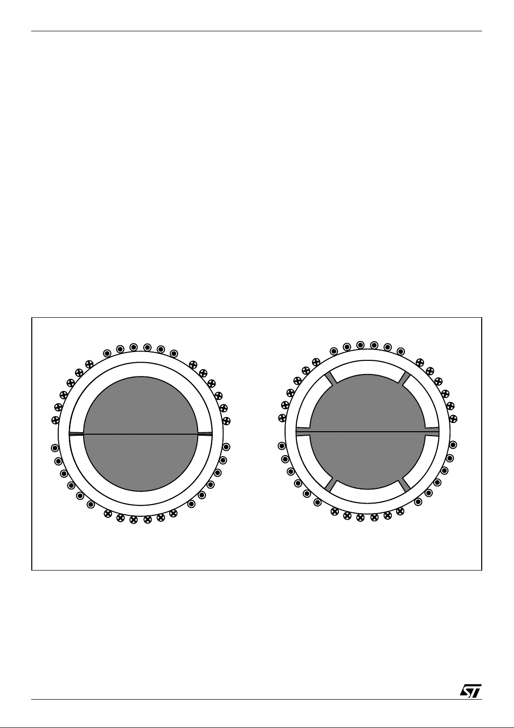
Figure 1 shows a cross section of a typical PM motor. The rotor has an iron core in the surface
of which is mounted a thin permanent magnet. An alternating magnet of opposing magnetization produces radially directed flux density across the air gap. This flux then reacts with currents in the stator windings to produce torque.
-
Figure 1. Cross Section of PM Motor
a
N
-b
a
N
-c
-b
S S
N
c
S
b
-a
1 Poles Pairs 3 Poles Pairs
The two most common types of brushless PM motors are classified as:
c
S
-a
-c
N
b
– synchronous, with a uniformly rotating stator field as an induction motor. This is also referred
to as PMAC,
– switched or trapezoidal, with stator fields that are switched in discrete steps. This is also re-
ferred to as PMDC.
4/36
2
Page 5
ST7MC PMAC SINE WAVE MOTOR CONTROL SOFTWARE LIBRARY
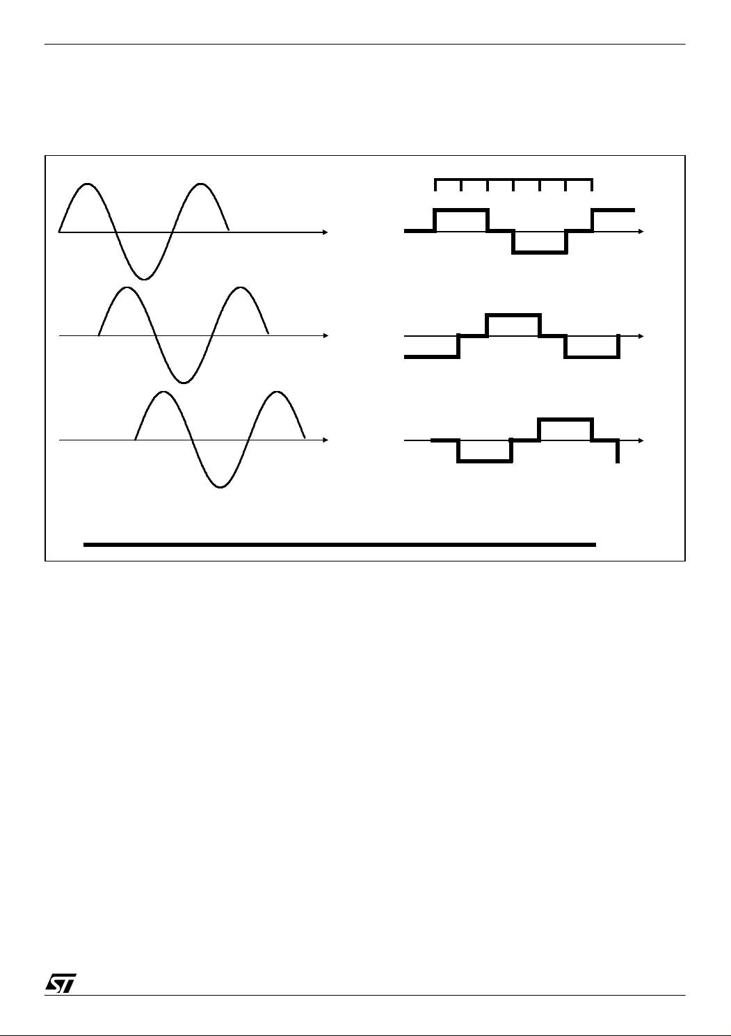
Figure 2 provides a direct comparison of ideal current excitation waveforms for typical three-
phase sinusoidal and trapezoidal PM machines.
Figure 2. Sinusoidal (PMAC) and Trapezoidal (PMDC or 6-step) Current Excitation
120°
240°
(a) Sinusoidal
Phase A
Phase B
Phase C
1
120°
2
240°
3
(b) Trapezoidal
456
2
The trapezoidal PM machine (also called PMDC or BLDC) is specifically designed to develop
nearly constant output torque when excited with a six-step switched current waveform. The
stator windings of the trapezoidal PM machine are concentrated into narrow phase belts. The
resulting back-EMF voltage induced in each stator phase winding during rotation can be mod
elled quite accurately as a trapezoidal waveform.
The sinusoidal PM machine also called PMAC or synchronous PM is specifically designed to
be excited with a sinusoidal current waveform. The stator windings of the sinusoidal PM ma
chine are instead typically distributed over multiple slots in order to approximate a sinusoidal
distribution. The resulting back-EMF waveforms generated by sinusoidal PM machine are, in
fact, sinusoidally shaped.
Except for the intrinsic characteristics of stator windings, a PM machine can be excited with
both drive methods without a great loss of efficiency, instead the main difference between the
two types of excitation is the acoustic noise generated. The abrupt variation of the trapezoidal
phase current generally introduces a great amount of acoustic and electronic noise in compar
ison to the sinusoidal phase current. Frequently the reduction of noise when a PM motor is excited with sinusoidal current in comparison to trapezoidal is appreciable even audibly and the
5/36
-
-
-
Page 6

ST7MC PMAC SINE WAVE MOTOR CONTROL SOFTWARE LIBRARY
efficiency loss cause by an incorrect type of waveform excitation is negligible. The drawback
of using the PMAC method is that the PMAC software library requires at least one sensor to
detect the rotor position. The elimination of the position sensor in sinusoidal PMAC machines
is more challenging since all three phases are continuously excited. This differs in the 6-step
PMDC method where one of the three phases is unexcited during each 60° electrical interval,
making it possible to get information about bemf zerocrossing. ST7MC is not designed to con
trol PMAC machines without sensors.
ST7MC Library Version 1.0.0 overview (CPU running at 8 MHz):
– Stator Frequency Range: From 0.2 Hz up to 680.0 Hz with the resolution dependent on the
PWM frequency (typically ~0.1Hz)
– Voltage Resolution: 8-bit modulation index
– 9 to 10-bit PWM generation for sine wave (typical resolution in the inaudible PWM range)
– PWM Frequency: can be set by default to 1.95, 3.9, 7.8, 12.5 and 15.66 kHz, with centered
pattern PWM generation
-
– Brake capabilities
– Speed reversal
– Speed acquisition from Hall sensors signal
– Speed regulation and control routines
– Free C source code
The 12.5 kHz switching frequency is proposed by default, providing a PWM resolution close to
10 bit with a 16-MHz CPU clock. In addition, this frequency is a good compromise between the
reduction of switching losses and acoustic noise (rejected in the inaudible range due to cen
tred mode PWM patterns).
Note: These figures are for information only; data provided in this software library may be dependent on the use of the final application and peripheral resources. It must also be noted that
it was built using robust oriented structures, therefore preventing the speed or code size from
being fully optimized.
Table 1 below summarizes the memory required by the software library, as it is delivered.
These metrics include non motor control related code, implemented for demo purposes (such
as ADC management, software time bases, etc.). These must therefore be considered only as
indicative figures, which will be lower in the final application.
-
6/36
Page 7

ST7MC PMAC SINE WAVE MOTOR CONTROL SOFTWARE LIBRARY
Table 1. Memory size metrics
ROM (bytes) RAM (bytes)
Cosmic 4.4d Metrowerks 1.1 Cosmic 4.4d Metrowerks 1.1
Closed Loop 5528 5965 164 189
Open Loop 4557 4747 164 166
1 WORKING ENVIRONMENT SET-UP
This section presents the available material needed to start working with the ST7MC and the
library discussed in this document.
1.1 DEVELOPMENT TOOLS
1.1.1 Integrated Development Environments (IDE)
This library has been compiled using Cosmic & Metrowerks C compilers, launched with
STVD7 release 2.5.4 (ST Visual Debugger) and STVD7 release 3.x.x.
A complete software package consists of:
– An IDE interface: ST's proprietary STVD7 (free download available on internet: www.stm-
cu.com), or third party IDE (e.g. Softec Microsystems' STVD7 for InDART-STX).
– A third party C-compiler: either Cosmic or Metrowerks (if needed, time limited evaluation ver-
sions can be obtained upon request).
The choice of the C Toolchain is left to the appreciation of the user. Both COSMIC and
METROWERKS are fully supported, and the dedicated workspace (compatible with 'STVD7'
& 'STVD7 for Indart') can be directly opened in the root of the library installation folder
(PMAC_Metrowerks.wsp, PMAC_Cosmic.wsp, pmacmotor.stw).
Note: You can use the 4K limited free version of Cosmic compiler to compile the software library. To do this you must disable the RS232 communication in the config.h as follows:
//#define ENABLE_RS232
In this case, to read the Phase Angle value you can run the program in Debugger mode, stop
it and use the Watch features.
1.1.2 Emulators
Two types of real-time development tools are available for debugging applications using
ST7MC:
– In-circuit debugger from Softec (sales type: STXF-INDART/USB).
The inDART-STX from Softec Microsystems is both an emulator and a programming tool. This
is achieved using the In-circuit debug module embedded on the MCU. The real-time features
7/36
Page 8

ST7MC PMAC SINE WAVE MOTOR CONTROL SOFTWARE LIBRARY
of the Indart include access to working registers and 2 breakpoint settings. However trace is
not available.
– ST7MDT50-EMU3 emulator
Full-featured emulator: real-time with trace capability, performance analysis, advanced breakpoints, light logical analyser capabilities, etc. It can also be a programming tool when used
with the delivered ICC ADDON module (where STMC-ICC is selected as the hardware target
in STVP7). This ICC-ADDON module allows In-Circuit-Debugging with STVD7.
1.1.3 Programmers
In order to program a MCU with the generated S19 file, you should also install the ST Visual
Programmer software (please visit our internet web-site) and use a dedicated programming
interface (stick programmer for example for In-Circuit-Programming). The Visual Program
ming tool provides an easy way to erase, program and verify the MCU content.
Please note that the inDART-STX from Softec Microsystems is also a programming tool (installation of DataBlaze Programmer software is required).
-
1.1.4 Starter Kit
The present software library was fully validated using the main hardware board (a complete inverter and control board) included in ST7MC-KIT/BLDC starter kit, and the demonstration PM
motor from AMETEK. The ST7MC-KIT/BLDC starter kit also includes a low-cost inDART hard
ware emulator, making this tool an ideal set for starting a project and evaluating/using the library.
Therefore, for rapid implementation and evaluation of the software discussed in this application note, it is recommended to acquire the ST7MC-KIT/BLDC starter kit and one of the two
compatible C-toolchain (or at least time limited evaluation versions).
1.2 LIBRARY SOURCE CODE
1.2.1 Download
The complete source files are available for free on the ST website (www.stmcu.com), as a zip
file in the Technical Literature and Support Files section. A Graphical User Interface (ver. 2.0)
which supports this type of motor is to be released soon by Softec. Check
www.softecmicro.com for updates.
Important Note: It is highly recommended to check for the latest releases of the library before
starting a new development, and then verify from time to time release notes to be aware of
8/36
Page 9

ST7MC PMAC SINE WAVE MOTOR CONTROL SOFTWARE LIBRARY
new features that might be of interest for the project. Registration mechanisms are also available on the web sites of ST and Softec Microsystems to automatically get update information.
1.2.2 File structure
Once the files are unzipped, the following library structure appears.
– Library release 1.0.0
This library contains the workspace for both the STVD7 2.5.x and STVD7 3.x IDEs. Two separate folders are provided, with different file structure based on the same set of source files.
This is to ensure the compatibility with STVD7 for inDART-STX, based on STVD7 2.5.4.
All build information is provided in makefiles and linker command files, in dedicated folders:
config\Cosmic and config\Metrowerks. Object files are also provided in dedicated folders.
Figure 3. Library Structure for release 1.0.0
PMAC
\config
\cosmic
\metrowerks
\object
\cosmic
\metrowerks
\source
\debug
\release
1.3 UTILITIES
1.3.1 lib.h file
The purpose of this header file is to provide useful macros and type re-definitions which will be
used throughout the entire library:
– Re-definition of data types using the following convention: a first letter indicating if a variable
is signed (s) or unsigned (u), plus a number indicating the number of available bits (for in
-
stance: u8, s16, etc.),
– Defines for assembly mnemonics used in C source code: Nop(), Trap(),...
– Common macros used for bit-level access (SetBit, ClrBit,...), to get the dimension of an array
(DIM[x]), etc.
1.4 TECHNICAL LITERATURE
More information can be found on the ST website (www.st.com/mcu).
9/36
Page 10
ST7MC PMAC SINE WAVE MOTOR CONTROL SOFTWARE LIBRARY
More specifically, latest documents and software can be found at:
http://mcu.st.com/devicedocs-ST7MC2N6-15.html
In addition, a Knowledge base (FAQ) and Forum are available at:
http://www.st.com/stonline/products/support/micro/st7/st7mc.htm.
2 PMAC BASIC PRINCIPLE
2.1 HOW A PM MOTOR CAN BE RUN IN SYNCHRONOUS SINE-WAVE MODE
PMAC machines are synchronous so the average torque can be produced only when the excitation is synchronized with the rotor frequency and instantaneous position. The most direct
and powerful means of ensuring that this requirement is always met is to continuously
measure the rotor's absolute angular position and rotational speed, so that the excitation can
be switched among the PMAC motor phases in exact synchronism with the rotor's motion.
This concept, known commonly as self-synchronization uses direct feedback of the rotor an
gular position to ensure that the PMAC machine never loss synchronization. Commonly Hall
sensors are used to get information about the angular position of rotor, finding the magnetic
flow direction caused by the permanent magnet running with the rotor.
-
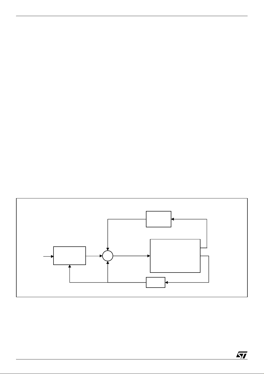
In Figure 4 is showed the block diagram of the PMAC self-synchronization algorithm implemented in the software library.
Figure 4. SELF-SYNCHRONIZATION ALGORITHMS FOR PMAC
Φ
A* sin(2πf+Φ)
A
The motor is supplied by a sinusoidal voltage waveform with amplitude A*, frequency f, and
phase Φ. The motor supplied by this signal is forced to run with frequency f*. For each con
troller cycle, to maintain the synchronism the new frequency of the rotor is measured and sup-
V/F
Limitation
A*
f
Phase
Synch.
f=f*
Motor
f*
-
10/36
Page 11

ST7MC PMAC SINE WAVE MOTOR CONTROL SOFTWARE LIBRARY
plied to the motor by the controller. Together with the frequency synchronization the phase Φ
must be synchronized according the position of the rotor read by the Hall sensors.
To avoid giving a high voltage value based on the current frequency, a V/F limitation curve is
used to fix the maximum voltage value supplied for that stator frequency.
2.2 VARIOUS CONFIGURATIONS OF HALL SENSORS
In commerce there are motors with different numbers of Hall sensors and various Hall sensor
configurations. The most common PM motors have three, two or one hall sensors. Motors with
three hall sensors can be arranged in two configuration types: 120° spatial distribution or 60°
spatial distribution. Motors with 2 hall sensors have spatial distribution of 90°.
Figure 5 sum-
marizes the most common Hall sensor configurations and the relative waveforms of the signals that are observed from the Hall sensors during an electrical cycle of the rotor.
2.3 PHASE ANGLE
We refer as “Phase Angle” the angle between the H1 edge transition and the 90° of A winding
sinus phase. This value must be set to get the synchronism between rotor and stator and to
optimize the efficiency of the motor. This value can be different for different speed and/or load
condition. See
Figure 6.
11/36
Page 12

ST7MC PMAC SINE WAVE MOTOR CONTROL SOFTWARE LIBRARY
Figure 5. Hall sensors configuration
3 Sensor 120°
H1
120°
H2 H3
H1
H2
H3
2 Sensor 90°
H1
90°
H2
H1
H2
3 Sensor 60°
H1
H2
H1
H2
H3
1 Sensor 180°
H1
H1
H3
60°
12/36
Page 13

ST7MC PMAC SINE WAVE MOTOR CONTROL SOFTWARE LIBRARY
Figure 6. Phase Angle is the angle between edge of H1 and 90° of A winding Sinus
Phase
Stator Voltage – Phase A
H1
Rotor
Flux
Stator
Flux
Rotor
Flux
Stator
Flux
C
H1
A
N
S
Phase_Angle
A
S
N
B
H1
Stator Voltage – Phase A
Phase_Angle
B C
H1
3 GETTING STARTED WITH PMAC LIBRARY
3.1 HARDWARE CONFIGURATION
3.1.1 Tools Required
– STMC Starter Kit
– Power Supply (Low or High voltage according to the motor needs)
– Oscilloscope, one current probe, three voltage probes
– Null modem cable for RS232 communications
3.1.2 Connect the hardware
– Connect the ST7MC starter kit board with the ICC isolator board through an ISP cable and
connect the ICC isolator board with the inDART board through an ISP cable.
13/36
Page 14

ST7MC PMAC SINE WAVE MOTOR CONTROL SOFTWARE LIBRARY
– Connect the inDART board to the PC through USB cable.
– Connect the motor phases to the J12 connector of ST7MC starter kit board and the hall sen-
sor signal to the J19 connector in any order.
– Set w14, w15, w16 to the unmarked jumper positions (hall sensor position). Open w13 jump-
er. Set w1 according to the power supply (Low voltage or High voltage)
– Connect the power supply to J3 connector of ST7MC starter kit board.
Note: To run the motor in High Voltage (>50 Vac) you must connect all the J8 jumpers (1-2, 3-
4. 5-6, 7-8) to filter the noise on the Hall sensor signals.
3.2 HOW TO RUN A PM MOTOR FOR THE FIRST TIME WITH THE LIBRARY AND HOW TO CONFIGURE THE PHASE ANGLE
To make the software run the motor correctly it's necessary to properly connect the phases
and hall sensor signals to the board. When we use one or two sensors there isn't a particular
correct setting as in both cases we can connect the wires in any order.
In case of three hall sensors (each 60 and 120 degree) we must perform the following procedure.
Set the software to run with only one sensor, open loop control method. Set the option to read
the phase angle through RV3 and set the RS232 communication. To do this you can open the
configuration file MTCParam.h and modify the following parameter:
#define Pole_Pair_Num "with the number of poles pairs of the motor"
#define Hall_Sensor_Num 1
Then we must ensure that the following line is uncommented in PMACparam.h.
#define Phase_Angle_RV3
This allows the Phase Angle to be set with the RV3 potentiometer.
And we must ensure that in Config.h the control mode is set to open loop with the following
line.
#define CONTROL 0
Another step that must be performed is to activate the RS232 communication by uncommenting the following line in Config.h.
#define ENABLE_RS232
14/36
Page 15

ST7MC PMAC SINE WAVE MOTOR CONTROL SOFTWARE LIBRARY
Then, compile the library using STVD7 for Indart STx and the Cosmic or Metrowerk compiler
and load the executable file into ST7MC microcontroller memory.
Before running the motor it's better to check if w14, w15, w16 are in the unmarked jumper positions (hall sensor position).
Set RV1 to ¼ of the full CW position to limit the stator voltage. Push the SW1 button (On/Off).
Rotate the RV3 from CCW to CW until the motor starts to run.
If the motor doesn't start, rotate RV1 CW a little to increase the stator voltage and retry to find
a position of RV3 that allows the motor to run.
If the motor runs in the opposite to the desired direction, swap phase B and phase C connection J12 and restart.
When the motor runs in the correct direction with one hall sensor you can stop the motor and
recompile the software with the three hall sensor settings.
#define Hall_Sensor_Num 3
Load the software and run the motor. Leave RV1 in the current position. Push SW1. Rotate
the RV3 from CCW to CW until the motor start to run.
Monitor the phase A current with the oscilloscope. If the motor runs but the phase current is
completely different from the sinusoidal waveform you must swap H2 with H3 connection in
the J19 connector.
To see if the connections are correct, you can view the hall sensors signals and the debug pin
signal from the microcontroller (MCDEM pin 43) to see if the sequence is right or wrong. You
can compare the signal you get with the
Figure 7.
Figure 7. Wrong and correct hall sensor sequence and debug pin
Wrong sensor sequence
Correct sensor sequence
15/36
Page 16

ST7MC PMAC SINE WAVE MOTOR CONTROL SOFTWARE LIBRARY
You can see in the Figure 7 that in the correct sequence there is a toggle of the debug pin for
each toggle of any one of hall sensors signal.
The position of RV3 can be rotated until the optimum Phase Angle is reached the optimum
value. Commonly we have two important Phase Angle values: one that minimizes the current
absorption and one that maximizes the speed. It is recommended to use the first as the op
timum Phase Angle.
Once the motor runs and the optimum Phase Angle is set, this value can be read by connecting the ST7MC starter kit board to the PC through a Null Modem cable and using Hyper
Terminal with the following parameters
– Bits per second: 38400
– Data bit: 8
– Parity: None
– Stop bit: 1
– Flow control: None
-
Then, we can set the phase angle as a fixed value by adding the optimum Phase Angle value
obtained from previous step to the two following lines from PMACparam.h. The same value
must be used in both defines if you want to keep the Phase Angle value constant for any stator
frequency.
#define Phi_min(u8) xx
#define Phi_max(u8) xx
And the following line must be commented
//#define PHASE_ANGLE_RV3
At this point, the software library has now been configured to run the motor and we have set
the right phase angle value.
3.3 COMPILING THE LIBRARY AND LOADING THE SOFTWARE
The steps below must be followed to generate the correct firmware to use the Starter Kit in
stand alone mode.
Notes:
1.The following steps require that the inDart - STX for ST7 System Software be installed.
16/36
Page 17

ST7MC PMAC SINE WAVE MOTOR CONTROL SOFTWARE LIBRARY
2. In order to compile a project linked to the STMicrocoelectronics Motor Control library, it is
possible to use :
– Full version of either the Metrowerks or Cosmic C compiler.
– Limited version of the Cosmic compiler (downloadable directly from www.cosmic-soft-
ware.com ).
Cosmic tools for STMicro ST7 family, free version limited to 4k.
Requires registration.
In this case it necessary to modify the following lines in in 32K.lkf file inside the folder config\cosmic as follows:
# STARTUP FILE
#C:\COSMIC\ST7\LIB\crts.st7
C:\COSMIC\CXST7_4K\LIB\crts.st7
# INTEGER LIBRARY FOR SMALL MEMORY MODEL
#C:\COSMIC\ST7\LIB\libims.st7
C:\COSMIC\CXST7_4K\LIB\libims.st7
# MACHINE LIBRARY FOR ALL MEMORY MODELS
#C:\COSMIC\ST7\LIB\libm.st7
C:\COSMIC\CXST7_4K\LIB\libm.st7
And set the correct path in the Project->Toolchains Path. Cosmic Builder Path:
C:\COSMIC\CXST7_4K
Run the STDV7 IDE. From the main menu, choose File > Open Workspace. Select the
"PMACMOTOR_COSMIC.wsp" if you use Cosmic compiler or
"PMACMOTOR_METROWERKS.wsp" if you use the Metrowerks compiler.
Select the "Build" command from the "Project" menu. The project will be compiled and built,
and an executable file will be generated.
Connect the InDart board with the ICC isolation board and supply the starter kit.
Press the debug button and then the MCU configuration button. Select the Device Code:
ST7FMC2N6B.
The option bytes must be configured by pressing the “Set option bytes” button and then by following the setup as displayed in Figure 8.
17/36
Page 18

ST7MC PMAC SINE WAVE MOTOR CONTROL SOFTWARE LIBRARY
Figure 8. Editing the Option Bytes
Then the software is ready to be loaded in the Flash of the ST7MC microcontroller by clicking
on the "Program” button. Then program window then appears and you must configure the set
tings as shown in Figure 9.
Figure 9. Loading software to Flash
-
Once the program has been loaded in to the micro, disconnect the cable between the Starter
Kit board and the ICC isolator board.
4 CONFIGURATION FILE
The PMAC software library can be easily configured using the following configuration files:
– Config.h: for setting general configuration parameters such as the control method, PWM res-
olution and for Kp & Ki tuning and RS232 communication
– MTCParam.h: for setting motor-specific parameters like the number of pole pairs, number of
hall sensors and dead time duration
18/36
Page 19

ST7MC PMAC SINE WAVE MOTOR CONTROL SOFTWARE LIBRARY
– PMACParam.h: for setting more specific parameters regarding PMAC control like startup pa-
rameters, frequency range, target frequency for closed loop operation, phase angle setting
and V/F curve
– MainParam.h: for setting the brake parameters.
4.1 CONFIGURATION PARAMETERS FOR LIBRARY USE
Config.h file
– CONTROL: This define sets the desired control method.
0 = Open Loop, 1 = Closed Loop
#define CONTROL0
– PWM_RESOLUTION: This define sets the resolution of PWM.
0 = 9-bit resolution (15.66 kHz, 7.9kHz, 3.9kHz, 1.95kHz of PWM), 1 = 10-bit resolution (12.5
kHz of PWM).
#define PWM_RESOLUTION1
– PI_PARAM_TUNING: This define sets up Ki & Kp to be read by RV2 RV3.
#define PI_PARAM_TUNING
– ENABLE_RS232: This define enables communication between the board and PC through a
serial cable.
#define ENABLE_RS232
MTCParam.h file
– POLE_PAIR_NUM: This define sets the number of the motor’s pole pairs.
#define POLE_PAIR_NUM ((u8)1) /* Number of motor's pole pairs */
– HALL_SENSOR_NUM: This define sets the Number of Hall sensors (3, 2 or 1)
#define HALL_SENSOR_NUM 1 /* Number of Hall Sensors */
– DEAD_TIME: This define sets the Dead time duration. The defined value is loaded into the
MDTG register value so that you can use the following formula.
MDTG
PCN DTE DTG
5
DTG
4
DTG
3
DTG
2
DTG
1
DTG
0
19/36
Page 20

ST7MC PMAC SINE WAVE MOTOR CONTROL SOFTWARE LIBRARY
DTG5 DTG4 Tdtg Dead time expression Dead time value Tdtg* Range*
0 X 2xTmtc (DTG[4..0]+1) x Tdtg From 1 to 32 Tdtg 125ns 0.125us to 4us
1 0 4xTmtc
(DTG[3..0]+17) x Tdtg From 17 to 32 Tdtg
1 1 8xTmtc 500ns 8.5us to 16us
#define DEADTIME((u8)4) // Define a Dead time of 625ns
250ns 4.25us to 8us
PMACParam.h file (start-up phase)
– VOLT_SLEW_RATE: This define sets the time in ms for each increment by one unit of stator
voltage during the startup phase in both open and closed loop.
#define VOLT_SLEWRATE ((u8)15) /* Slope of startup voltage */
– STARTUP_STATOR_FREQ: This define sets the stator frequency during asynchronous
startup
#define STARTUP_STATOR_FREQ ((u16) 50) /* Frequency of the Asynchronous
phase of startup must be major or equal than LOWEST_FREQ*/
– START_TIMEOUT: This define sets the timeout of the start-up phase.
#define START_TIMEOUT((u16)5000) /* Resolution: 1ms */
– HIGHEST_FREQ: This sets the Max stator frequency with a resolution of 0.1 Hz
– LOWES_FREQ: this sets the minimum stator frequency with a resolution of 0.1 Hz
#define HIGHEST_FREQ((u16)5000)/* Sine wave Max Frequency 500 Hz*/
#define LOWEST_FREQ((u16)5) /* Sine wave Min Frequency 0.5 Hz*/
– TARGET_FREQ_CL: This define sets the target rotor frequency with the closed loop control
method with a resolution of 0.1 Hz
#define TARGET_FREQ_CL 500 /* Target frequency 50 Hz */
– PHI_MIN, PHI_MAX, PHI_LOWFREQ, PHI_HIGHFREQ: Phase angle definition. See Figure
6 and Figure 10.
20/36
Page 21

ST7MC PMAC SINE WAVE MOTOR CONTROL SOFTWARE LIBRARY
Figure 10. Phase Angle versus frequency curve
Phase Angle
PHI_MAX
PHI_MIN
PHI_LOWFREQ PHI_HIGHFREQ
#define PHI_MIN (u8) 140
#define PHI_MAX (u8) 160
#define PHI_LOWFREQ (u16) 500// 50 Hz
#define PHI_HIGHFREQ (u16) 2500// 250 Hz
Frequency
– PHASE_ANGLE_RV3: This define configures the Phase angle to be set using RV3 potenti-
ometer.
#define PHASE_ANGLE_RV3 /* If defined the Phase angle is read by RV3 */
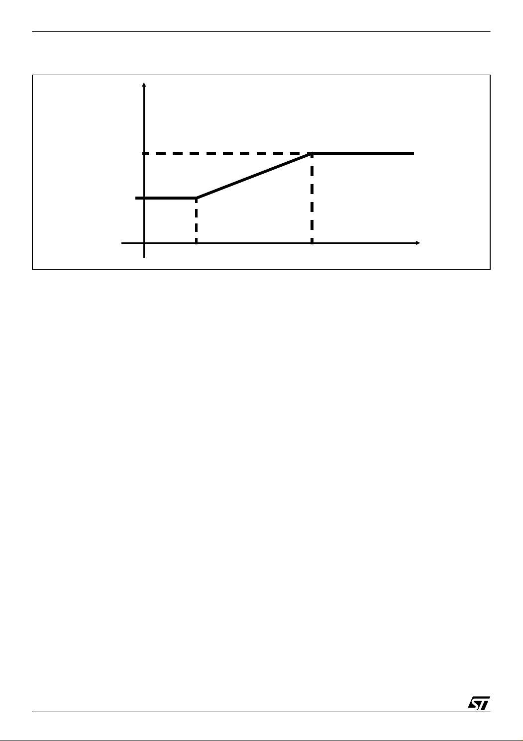
– V_MAX, V_MIN, VF_LOWFREQ_LIMIT, VF_HIGHFREQ_LIMIT: These defines set the V/F
curve. See
Figure 11. V/F curve definition. The V/F curve is used to limit the maximum stator
voltage applied to the value below that curve. This curve fixes a maximum stator voltage value in relation to the actual stator frequency.
21/36
Page 22
ST7MC PMAC SINE WAVE MOTOR CONTROL SOFTWARE LIBRARY
Figure 11. V/F curve definition
Stator Voltage
V_MAX
V_MIN
VF_LOWFREQ_LIM VF_HIGHFREQ_LIM
#define V_MAX ((u8)255)
#define V_MIN ((u8)100)
#define VF_LOWFREQ_LIMIT ((u16)200)// 20 Hz
#define VF_HIGHFREQ_LIMIT ((u16)1000)// 100 Hz
Frequency
– V_F_LIM: This define represents the V/F limitation and can be excluded by commenting.
//#define V_F_LIM // Exclude V/F limitation if commented
Caution: Disabling the V/F limitation can be dangerous.
– SLEW_LIMIT: This define sets the voltage variation rate during run time, expressed in milli-
seconds. The stator voltage can increment or decrement by one unit each SLEW_LIMIT millisecond.
#define SLEW_LIMIT((u8)10)// 10 milliseconds
– REG_LOOP_TIME: This define sets the sampling frequency of the PI regulator, expressed
in milliseconds.
#define REG_LOOP_TIME((u8)10)
MainParam.h
– BRAKE_VOLTAGE: This is the voltage modulation index of the sinusoidal waveform applied
during the brake. The greater this value, the stronger the brake is but also the higher the cur
rent that flows into the motor during the brake.
22/36
-
Page 23

ST7MC PMAC SINE WAVE MOTOR CONTROL SOFTWARE LIBRARY
– BRAKE_MIN_SPEED: This is the minimum rotor speed to be reached before to end the
brake phase express in 0.1 Hz. See
Section 5.5 Braking Strategy
4.2 CONFIGURATION EXAMPLE
4.2.1 Three hall sensors 60° or 120° settings
In MTCparam.h
#define HALL_SENSOR_NUM3
4.2.2 Two hall sensors 90° settings
In MTCparam.h
#define HALL_SENSOR_NUM 2
4.2.3 One hall sensor settings
In MTCparam.h
#define HALL_SENSOR_NUM 1
4.2.4 Open loop settings
In Config.h
#define CONTROL 0
4.2.5 Closed loop settings
In Config.h
#define CONTROL 1
In PMACparam.h
#define TARGET_FREQ_CL 500 // 50Hz of target frequency
5 LIBRARY FUNCTIONALITIES
5.1 CAPTURE INTERRUPT
The flowchart of the Capture Event is shown in Figure 12.
23/36
Page 24

ST7MC PMAC SINE WAVE MOTOR CONTROL SOFTWARE LIBRARY
Figure 12. Capture event interrupt Flowchart
MTC_C_D_IT
MPHST_prev = MPHST
Yes
MPHST = MCIB
Yes
MPHST = MCIC
Yes
MPHST = MCIA
Yes
MPHST_prev
= MCIA
MPHST_prev
= MCIB
MPHST_prev
= MCIC
Direction = CW
Yes
MPHST = MCIC
Yes
MPHST = MCIA
Yes
MPHST = MCIB
Yes
MPHST_prev
= MCIA
MPHST_prev
= MCIB
MPHST_prev
= MCIC
Yes
Hall Sensor
Num = 3
MPHST_prev
= MCIA
Yes
MPHST = B
Hall Sensor
Num = 2
Yes
MPHST_prev
= MCIA
MPHST = A
Yes
Step_Index = 0
24/36
Yes
PBDR & 0x02
Direction = CW
Step_Index =
HALL_SENSOR_NUM
Phase = Pase Angle + PhaseVal [Step_Index]
Yes
Step_Index =
HALL_SENSOR_NUM
Rotor Speed
Measurement
Return
PBDR & 0x02
Step_Index = 0 Step_Index ++
Page 25

ST7MC PMAC SINE WAVE MOTOR CONTROL SOFTWARE LIBRARY
The capture event occurs when the selected MCIx input receives one edge transition from the
sensors from low to high or from high to low. This lets the software know the rotor position and
sets the correct phase value to be provided by the sine wave generation routine.
The software distinguishes between 3 cases:
– 3 Hall sensors
– 2 Hall sensors
– 1 Hall sensor
The software must set the port MCIx from where the next expected transition occurs. So the
software must discern between the hall sensors sequence.
If you have set three sensors and the sequence is H1-H2-H3 then:
– If MCIA transition occurs, the next expected will be MCIB
– If MCIB transition occurs, the next expected will be MCIC
– If MCIC transition occurs, the next expected will be MCIA
Otherwise if we have set the sequence H3-H2-H1 then:
– If MCIA transition occurs, the next expected will be MCIC
– If MCIB transition occurs, the next expected will be MCIA
– If MCIC transition occurs, the next expected will be MCIB
This is the same for each 60° and 120° hall sensor. The software should be written keeping in
mind that a clockwise direction of the rotor generates the sequence H3-H2-H1.
If you have set two sensors, regardless the hall sensor sequence, the software follows the
rule:
– If MCIA transition occurs, the next expected will be MCIB
– If MCIB transition occurs, the next expected will be MCIA
If you have set one sensor, the transition expected is only in the port MCIA.
Then, after each capture event, the software must calculate the correct phase to be applied to
the stator voltage sine wave. The main synchronization is between winding A and hall sensor
H1 so the software checks if the actual transition is on the MCIA input. If the transition on
MCIA occurs the sine wave generated relative to windings A is forced to phase 0° if MCIA
switches from low to high or to phase 180° if MCIA switches from high to low. This is per
formed checking the state of PB2 connected with MCIA.
-
PhaseVal is a vector that contains the phase value to be supplied on each sensor transition,
expressed in u16 value so we have:
25/36
Page 26

ST7MC PMAC SINE WAVE MOTOR CONTROL SOFTWARE LIBRARY
PhaseVal: 6 values for 3 sensors
0° 60° 120° 180° 240° 300°
0 10923 21845 32768 43691 54613
PhaseVal: 4 values for 2 sensor
0° 90° 180° 270°
0 16384 32768 49152
PhaseVal: 2 values for 1 sensor
0° 180°
0 32768
Step_Index is a variable which points into the PhaseVal to the last phase used for resynchronization so when the software receives one capture event that isn't in the MCIA input the
Step_Index is incremented and the resynchronization will be performed.
Finally, the software performs the rotor speed measurement with the information of two consecutive hall sensor edge events. The rotor speed measurement is performed to force the
synchronism between stator and rotor frequency.
5.2 START UP PROCEDURE
The startup procedures are defined in ACMotor.c module:
– ACM_InitSoftStart()
– ACM_SoftStart()
– ACM_SoftStartOL(TargetVoltage)
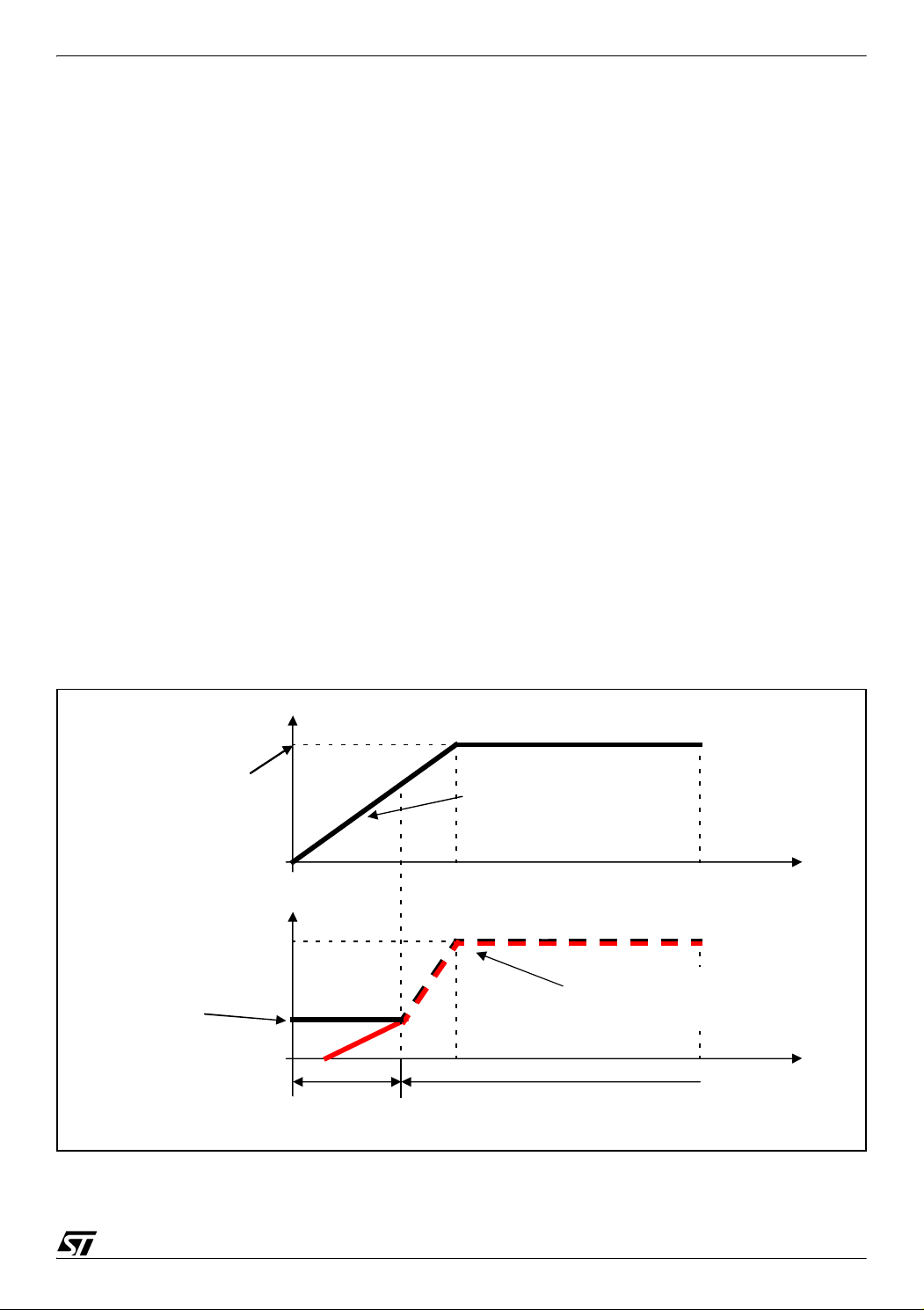
Open loop strategy
Provide a ramp of stator voltage with fixed slewrate set in VOLT_SLEW_RATE. Initially the
stator frequency is fixed to the value set up in STARTUP_STATOR_FREQ. When the rotor
frequency reaches STARTUP_STATOR_FREQ the synchronous mode starts and stator fre
quency is fixed to be equal to the reported rotor frequency. The startup phase finishes when
the stator voltage reaches TargetVoltage. This value is actually the reference stator voltage
fixed by RV1. See
Figure 13.
-
26/36
Page 27
ST7MC PMAC SINE WAVE MOTOR CONTROL SOFTWARE LIBRARY
Closed loop strategy
Provide a ramp of stator voltage with fixed slewrate set in VOLT_SLEW_RATE. Initially the
stator frequency is fixed to the value set up in STARTUP_STATOR_FREQ. When the rotor
frequency reaches STARTUP_STATOR_FREQ the synchronous mode starts and the stator
frequency is fixed to be equal to the reported rotor frequency and the startup phase finishes.
Figure 14.
See
ACM_InitSoftStart: this procedure is common to open and closed loop control methods and
must be called before ACM_SoftStart or ACM_SoftStartOL. It is used to perform the fol
lowing tasks:
– Initialize the Hall sensor acquisition.
– Set the initial value of stator voltage and frequency (stator voltage equal to zero and stator
frequency to LOWEST_FREQ).
– Set the time interval in ART (Automatic Reload Timer) equal to VOLT_SLEWRATE (succes-
sively for each ART interrupt the SoftStart or SoftStartOL procedures increase the stator voltage by one).
-
– Set the timeout if in a closed loop.
Figure 13. Open loop startup strategy
Stator Voltage*
Fixed by RV1, that is the
reference stator voltage for
open loop mode*
Stator Frequency
Rotor Frequency
Startup_Stator_Freq
Asynchronous mode
*
For Stator Voltage is intend the voltage modulation index [0,255]
Voltage_SlewRate
between the increasing by one of
stator voltage
Synchronous mode
: The time
Time Out
During Synchronous mode the
Frequency
rotor frequency.
is imposed to be equal to the
Time
Stator
Time Time Out
27/36
Page 28

ST7MC PMAC SINE WAVE MOTOR CONTROL SOFTWARE LIBRARY
Figure 14. Closed loop startup strategy
Stator Frequency
Rotor Frequency
Target Rotor Freq
Startup_Stator_Freq
* For Stator Voltage is intend the voltage modulation index [0,255]
Stator Voltage*
imposed by RV1
Startup phase
Asynchronous mode
Regulation Phase
Voltage_SlewRate
increasing by one of stator voltage
Synchronous mode
: The time between the
Time Out
During Syncronous mode the
Frequency
rotor frequency.
is imposed to be equal to the
If Time_out is reach during the Startup
phase fails to start.
Time
Stator
Time Time Out
ACM_SoftStartOL(TargetVoltage): this is used to perform the open loop startup strategy.
The function has one parameter called TargetVoltage that set the maximum stator voltage
modulation index (from 0 to 255) that can be reached during the startup phase. The function
performs the following task:
– Each VOLT_SLEW_RATE millisecond increases the stator voltage by one unit until the Tar-
getVoltage is reached.
– If the rotor frequency is below LOWEST_FREQ then the stator frequency is set to the mini-
mum admissible value (LOWEST_FREQ).
– If the rotor frequency is above LOWEST_FREQ the synchronism is imposed setting Stator
frequency equal to rotor frequency.
This function is called from the main loop by the function StartMotor. StartMotor sets the TargetVoltage to a value obtained from RV1. In open loop, RV1 sets the stator voltage modulation
index so the startup phase finishes when this value is reached.
ACM_SoftStartOL returns a value of type SystStatus_t that can be:
– START if the startup phase is ongoing,
– RUN if the startup phase is finished.
StartMotor returns this value in the main loop to change the actual status if needed.
28/36
Page 29

ST7MC PMAC SINE WAVE MOTOR CONTROL SOFTWARE LIBRARY
Note: StartMotor is a function that is compiled differently depending on whether closed loop or
open loop is defined.
ACM_SoftStart(): this is used to perform the closed loop startup strategy. The function performs the following tasks:
– Soft start by increasing the voltage from zero to a predefined value.
– Initialization of the Hall sensor acquisition for closed loop mode.
– Monitoring of the Hall sensor feedback to limit the starting voltage (and therefore limit the
starting torque).
– At the end of the Soft start initialize the regulation procedure.
This function is called from the main loop by the function StartMotor (the version compiled
with closed loop define).
ACM_SoftStart returns a value of type StartStatus_t that can be:
– START_ONGOING if the startup phase is ongoing,
– START_OK if the startup phase is successfully finished,
– START_FAIL if time out is reached and the rotor frequency if below the minimum value.
The startMotor (Closed Loop) returns a value of type SystStatus_t that can be:
– START if the startup phase is ongoing,
– RUN if the startup phase is successfully finished,
– FAULT if the startup phase fails.
The value returned is used in the main loop to change the actual status.
5.3 DIRECTION PROCEDURES
The direction procedures are defined in the MTC.c module:
– MTC_Toggle_Direction()
– MTC_Set_ClockWise_Direction()
– MTC_Set_CounterClockWise_Direction()
– MTC_GetRotationDirection()
These functions are used to set, modify or get an indication of the actual rotating direction. Rotation direction change is achieved by modifying the sign of the variable holding the phase
shift between the three phases (either 120° or -120°).
Note: The clockwise direction is defined randomly. The real direction will only depend on the
physical connection of the motor.
29/36
Page 30

ST7MC PMAC SINE WAVE MOTOR CONTROL SOFTWARE LIBRARY
The return value of MTC_GetRotationDirection() is of type Direction_t and can be CLOCKWISE or COUNTERCLOCKWISE.
Warning: No tests are performed on the motor status (running or stopped) inside these func-
tions.
You must therefore be sure that the motor is stopped before calling any of the three routines
able to modify the rotation direction. On the contrary, if the direction is changed while the
motor is running, it can immediately become a generator, thus injecting reactive energy in the
high voltage DC bus capacitor, causing the voltage to go above the capacitor’s maximum
voltage rating.
5.4 REGULATION
The functions that perform the regulation are defined in the ACMotor.c module:
– ACM_InitSpeedReg()
– ACM_SpeedRegulation()
The ACM_InitSpeedReg function must be called before calling the regulation routine
ACM_Speedregulation (typically after completing the ACM_SoftStart function). It guarantees
a smooth transition from open loop to closed loop operations.
It performs the initialization of the integral term of the PI regulator (VoltageIntegralTerm) formula shown below and resets the PI regulator clamping flags.
The VoltageIntegralTerm is set using the formula:
Voltage = Integral + Proportional > Integral = Current Voltage - Proportional
ACM_SpeedRegulation performs a closed loop rotor speed control (in terms of the rotor frequency) to obtain the voltage to be supplied on the stator winding. This function uses a PI
(Proportional and Integral) regulation algorithm to determine the most appropriate voltage
value to get the expected rotor frequency. The function returns the modulation index voltage
(u8).
Caution 1 This function is executed regardless of the regulator sampling time; this period
must be managed by the calling function actually DoMotorControl().
Caution 2 The sine wave parameters are not modified in this routine; the MTC_UpdateSine
function has to be called after this function using the voltage value returned.
Note: For more information about all other routines in the library see the application note 1904
“ST7MC THREE-PHASE AC INDUCTION MOTOR CONTROL SOFTWARE LIBRARY”. The
PMAC software library, indeed, contains the same functions and configuration files as the AC
Induction motor software library with the exception of the above explained in this AN.
30/36
Page 31

ST7MC PMAC SINE WAVE MOTOR CONTROL SOFTWARE LIBRARY
5.5 BRAKING STRATEGY
During the braking process, a sinusoidal waveform is provided to the motor to generate a statoric field 90° in advance with respect to the rotoric field. The sinusoidal waveform supplied for
the brake has a ramp of voltage modulation index that reaches a user defined value. This
braking is active until the motor slows down to the minimum rotor frequency fixed by the user.
During the braking process, the self synchronization mechanism is maintained.
6 RESULTS
6.1 OSCILLOSCOPE ACQUISITION OF PHASE CURRENT WAVEFORM
PMAC motor with three 120° Hall sensors
Figure 15 (a) shows the oscilloscope acquisition during the startup phase.
Channel description:
– CH1: Hall sensor H1
– CH2: Hall sensor H2
– CH3: Hall sensor H3
– CH4: Current probe on phase A
Figure 15. PMAC motor with three 120° Hall sensors
(a) Startup Phase (b) Run phase
Figure 15 (b) shows the oscilloscope acquisition during the run phase.
Channel description:
– CH1: Hall sensor H1
31/36
Page 32

ST7MC PMAC SINE WAVE MOTOR CONTROL SOFTWARE LIBRARY
– CH2: Hall sensor H2
– CH3: Hall sensor H3
– CH4: Current probe on phase A
AMETEK motor with three 60° Hall sensors and with only one sensor setting
Figure 16 (a) shows the oscilloscope acquisition during the run phase using three hall sen-
sors.
Channel description:
– CH1: MC01 HiRes (stator voltage of phase A)
– CH2: MC03 HiRes (stator voltage of phase B)
– CH3: MC05 HiRes (stator voltage of phase C)
– CH4: Current probe on phase A
Figure 16. AMETEK motor three 60° Hall sensors or one sensor mode.
(a) three 60° Hall sensors (b) one sensor mode
In Figure 16 (b) shows the oscilloscope acquisition during the run phase using only one sensor
mode.
Channel description:
– CH1: MC01 HiRes (stator voltage of phase A)
– CH2: MC03 HiRes (stator voltage of phase B)
– CH3: MC05 HiRes (stator voltage of phase C)
– CH4: Current probe on phase A
32/36
Page 33

ST7MC PMAC SINE WAVE MOTOR CONTROL SOFTWARE LIBRARY
Dynamic performance of a PI controller
In the Figures below are showed two graphs of the speed measured of the Ametek motor run
in PMAC mode with 3 Hall sensors. The graphs show the rotor speed variation (express in 0,1
Hz) that follow an abrupt rise of target frequency from 0 Hz to 150 Hz (a value of 1500 in the
graph).
The first graph is performed using Kp = 50 and Ki = 10 and sampling time of 10 ms.
The second is performed using Kp=200 and Ki = 10.
Figure 17. Dynamic performance (Kp = 50 and Ki = 10)
1800
1600
1400
1200
1000
800
600
400
Frequency (x10 Hz)
200
0
1 30 59 88 117 146 175 204 233 262 291 320 349 378 407 436 465 494 523 552 581 610 639 668 697 726 755 784 813 842 871 900
Time ( x ~0.3ms )
Figure 18. Dynamic performance (Kp=200 and Ki = 10)
1600
1400
1200
1000
800
600
400
Frequency (x10 Hz)
200
0
1 24 47 70 93 116 139 162 185 208 231 254 277 300 323 346 369 392 415 438 461 484 507 530 553 576 599 622 645 668 691 714 737 760 783
Time ( x ~0.3ms )
33/36
Page 34

ST7MC PMAC SINE WAVE MOTOR CONTROL SOFTWARE LIBRARY
6.2 MOTOR CONTROL RELATED CPU LOAD IN THE APPLICATION
6.2.1 Estimation
The CPU load consumption induced by the motor control mainly comes from three tasks
which are listed below.
Sine wave generation
This is the main source of work for the CPU and it is done in interrupts (MTC_U_CL_SO_IT)
at a fixed rate: the related value is thus constant whatever the sine wave frequency or voltage;
with the default setting MREP = 3 the CPU load measured is 25%
Speed feedback processing
This is also done in interrupt (MTC_C_D_IT), at a rate proportional to the motor speed. For instance, running at 5000RPM, this gives:
5000RPM / 30 = 166.6Hz rotational frequency
CPU load for 1 sensor setting: 0.4% (23µs duration time)
CPU load for 3 sensors setting: 3% (30µs duration time)
PI regulator
This term includes the MTC_GetRotorFreq,
ACM_SpeedRegulation and the MTC_UpdateSine functions (totally 1.7ms).
This contribution is inversely proportional to the sampling time of the PI regulator.
For instance, if Tsampling = 20ms, this will lead to:
(1.7) / 20 =8.5%.
Total CPU load
Here below is an example for a Ametek motor running at 5000RPM:
Total CPU load = 8.5% (PI) + 25% (sine) + 3% (speed feedback) = 36.5%.
Note: for open loop applications, speed feedback, synchronization and sine wave generation are the only
parameters to be taken into account.
34/36
Page 35

ST7MC PMAC SINE WAVE MOTOR CONTROL SOFTWARE LIBRARY
7 REVISION HISTORY
Table 2. Document revision history
Date Revision Changes
14-Dec-2004 1 Initial release
16-Jul-2007 2 Removed references to obsolete products
35/36
Page 36

ST7MC PMAC SINE WAVE MOTOR CONTROL SOFTWARE LIBRARY
Please Read Carefully:
Information in this document is provided solely in connection with ST products. STMicroelectronics NV and its subsidiaries (“ST”) reserve the
right to make changes, corrections, modifications or improvements, to this document, and the products and services described herein at any
time, without notice.
All ST products are sold pursuant to ST’s terms and conditions of sale.
Purchasers are solely responsible for the choice, selection and use of the ST products and services described herein, and ST assumes no
liability whatsoever relating to the choice, selection or use of the ST products and services described herein.
No license, express or implied, by estoppel or otherwise, to any intellectual property rights is granted under this document. If any part of this
document refers to any third party products or services it shall not be deemed a license grant by ST for the use of such third party products
or services, or any intellectual property contained therein or considered as a warranty covering the use in any manner whatsoever of such
third party products or services or any intellectual property contained therein.
UNLESS OTHERWISE SET FORTH IN ST’S TERMS AND CONDITIONS OF SALE ST DISCLAIMS ANY EXPRESS OR IMPLIED
WARRANTY WITH RESPECT TO THE USE AND/OR SALE OF ST PRODUCTS INCLUDING WITHOUT LIMITATION IMPLIED
WARRANTIES OF MERCHANTABILITY, FITNESS FOR A PARTICULAR PURPOSE (AND THEIR EQUIVALENTS UNDER THE LAWS
OF ANY JURISDICTION), OR INFRINGEMENT OF ANY PATENT, COPYRIGHT OR OTHER INTELLECTUAL PROPERTY RIGHT.
UNLESS EXPRESSLY APPROVED IN WRITING BY AN AUTHORIZED ST REPRESENTATIVE, ST PRODUCTS ARE NOT
RECOMMENDED, AUTHORIZED OR WARRANTED FOR USE IN MILITARY, AIR CRAFT, SPACE, LIFE SAVING, OR LIFE
SUSTAINING APPLICATIONS, NOR IN PRODUCTS OR SYSTEMS WHERE FAILURE OR MALFUNCTION MAY RESULT IN
PERSONAL INJURY, DEATH, OR SEVERE PROPERTY OR ENVIRONMENTAL DAMAGE. ST PRODUCTS WHICH ARE NOT
SPECIFIED AS "AUTOMOTIVE GRADE" MAY ONLY BE USED IN AUTOMOTIVE APPLICATIONS AT USER’S OWN RISK.
Resale of ST products with provisions different from the statements and/or technical features set forth in this document shall immediately void
any warranty granted by ST for the ST product or service described herein and shall not create or extend in any manner whatsoever, any
liability of ST.
ST and the ST logo are trademarks or registered trademarks of ST in various countries.
Information in this document supersedes and replaces all information previously supplied.
The ST logo is a registered trademark of STMicroelectronics. All other names are the property of their respective owners.
© 2007 STMicroelectronics - All rights reserved
STMicroelectronics group of companies
Australia - Belgium - Brazil - Canada - China - Czech Republic - Finland - France - Germany - Hong Kong - India - Israel - Italy - Japan -
Malaysia - Malta - Morocco - Singapore - Spain - Sweden - Switzerland - United Kingdom - United States of America
www.st.com
36/36
 Loading...