

Page 1

AN1946
APPLICATION NOTE
SENSORLESS BLDC MOTOR CONTROL
AND BEMF SAMPLING METHODS WITH ST7MC
1 INTRODUCTION
Permanent Magnet Brushless DC Motors are replacing brush motors in numerous applications as they offer significant energy efficiency improvements, lower acoustic noise and better
reliability to name a few advantages. To be driven and controlled properly, 3-phase Perma
nent Magnet Brushless motors require a 3 half bridge "inverter" topology to deliver a 6-step or
sine wave signal. They also require the electronic commutation of motor phases to respect the
synchronization between statoric flux and the permanent magnet of the rotor.
Generally, a BLDC motor drive uses one or more sensors giving positional information to keep
synchronization. Such implementation results in a higher drive cost due to sensor wiring and
implementation in the motor. Moreover, sensors cannot be used in applications where the
rotor is in closed housing and the number of electrical entries must be kept to a minimum such
as in a compressor, or in applications where the motor is immersed in a liquid such as some
pumps.
-
Therefore, for cost and technical reasons, the BLDC sensorless drive is an essential capability
of a brushless motor controller. The ST7MC allows various implementations of sensorless
BLDC control with the lowest possible system cost while maintaining the highest performance.
This paper describes in detail these topologies, their advantages and drawbacks, as well as
their practical implementation. Most of the examples in this paper make use of the ST7MCKIT/BLDC Starter kit which allows easy implementation of most topologies described.
AN1946 Rev. 2 1/35
1
Page 2

Table of Contents
1 INTRODUCTION . . . . . . . . . . . . . . . . . . . . . . . . . . . . . . . . . . . . . . . . . . . . . . . . . . . . . . . . .1
2 SENSORLESS DRIVE PRINCIPLE . . . . . . . . . . . . . . . . . . . . . . . . . . . . . . . . . . . . . . . . . . 3
2.1 SAMPLING METHOD . . . . . . . . . . . . . . . . . . . . . . . . . . . . . . . . . . . . . . . . . . . . . . . . . . . . . . . . .6
3 SAMPLING AT END OF PWM OFF STATE (ST PATENTED "3 RESISTOR" METHOD) 7
3.1 DESCRIPTION . . . . . . . . . . . . . . . . . . . . . . . . . . . . . . . . . . . . . . . . . . . . . . . . . . . . . . . . . . . . . . .7
3.2 ST7MC-KIT/BLDC PRACTICAL IMPLEMENTATION . . . . . . . . . . . . . . . . . . . . . . . . . . . . . . . .8
3.3 PRACTICAL RESULTS . . . . . . . . . . . . . . . . . . . . . . . . . . . . . . . . . . . . . . . . . . . . . . . . . . . . . . . .9
4 SAMPLING DURING PWM ON STATE (INDUSTRY STANDARD “CLASSICAL” BEMF
METHOD) . . . . . . . . . . . . . . . . . . . . . . . . . . . . . . . . . . . . . . . . . . . . . . . . . . . . . . . . . . . . . . . 11
4.1 DESCRIPTION . . . . . . . . . . . . . . . . . . . . . . . . . . . . . . . . . . . . . . . . . . . . . . . . . . . . . . . . . . . . . .11
4.2 PRACTICAL IMPLEMENTATION OF SAMPLING DURING PWM ON . . . . . . . . . . . . . . . . . .13
4.2.1 Components dimensioning . . . . . . . . . . . . . . . . . . . . . . . . . . . . . . . . . . . . . . . . . . . . . . .14
4.2.2 Size of Reference Voltage . . . . . . . . . . . . . . . . . . . . . . . . . . . . . . . . . . . . . . . . . . . . . . . .15
4.2.3 Size of BEMF sensing network . . . . . . . . . . . . . . . . . . . . . . . . . . . . . . . . . . . . . . . . . . . .15
4.3 PRACTICAL IMPLEMENTATION OF THE "CLASSICAL" METHOD, USING THE ST7MC-KIT/
BLDC STARTER KIT 17
4.4 PRACTICAL RESULTS . . . . . . . . . . . . . . . . . . . . . . . . . . . . . . . . . . . . . . . . . . . . . . . . . . . . . . .18
5 SAMPLING DURING PWM ON STATE USING DIGITAL FILTER . . . . . . . . . . . . . . . . . 20
5.1 DESCRIPTION . . . . . . . . . . . . . . . . . . . . . . . . . . . . . . . . . . . . . . . . . . . . . . . . . . . . . . . . . . . . . .20
5.2 PRACTICAL IMPLEMENTATION . . . . . . . . . . . . . . . . . . . . . . . . . . . . . . . . . . . . . . . . . . . . . . .21
5.2.1 Sizing of network on motor phase . . . . . . . . . . . . . . . . . . . . . . . . . . . . . . . . . . . . . . . . . .22
5.2.2 Sizing of Network of Voltage Reference . . . . . . . . . . . . . . . . . . . . . . . . . . . . . . . . . . . . .23
5.3 RECORDS OF DIGITAL SAMPLING DURING PWM ON . . . . . . . . . . . . . . . . . . . . . . . . . . . . . 24
6 MIXED SAMPLING AT END OF PWM OFF AND DURING PWM ON . . . . . . . . . . . . . . 25
7 BEMF SAMPLING AT HIGH FREQUENCY METHOD (USED IN PULSE AMPLITUDE
MODULATION METHOD) . . . . . . . . . . . . . . . . . . . . . . . . . . . . . . . . . . . . . . . . . . . . . . . . . . 27
8 CHOICE OF SAMPLING METHOD . . . . . . . . . . . . . . . . . . . . . . . . . . . . . . . . . . . . . . . . . 27
9 CONCLUSION . . . . . . . . . . . . . . . . . . . . . . . . . . . . . . . . . . . . . . . . . . . . . . . . . . . . . . . . . 28
10 APPENDIX - IMPROVED BEMF DETECTION FOR LOW SPEED AND LOW VOLTAGE
APPLICATIONS . . . . . . . . . . . . . . . . . . . . . . . . . . . . . . . . . . . . . . . . . . . . . . . . . . . . . . . . . .29
10.1 THEORY . . . . . . . . . . . . . . . . . . . . . . . . . . . . . . . . . . . . . . . . . . . . . . . . . . . . . . . . . . . . . . . . . . 29
10.2 PROBLEMS . . . . . . . . . . . . . . . . . . . . . . . . . . . . . . . . . . . . . . . . . . . . . . . . . . . . . . . . . . . . . . . .30
10.2.1Solution . . . . . . . . . . . . . . . . . . . . . . . . . . . . . . . . . . . . . . . . . . . . . . . . . . . . . . . . . . . . . .31
10.3 RESULT . . . . . . . . . . . . . . . . . . . . . . . . . . . . . . . . . . . . . . . . . . . . . . . . . . . . . . . . . . . . . . . . . . .32
10.4 CONCLUSION . . . . . . . . . . . . . . . . . . . . . . . . . . . . . . . . . . . . . . . . . . . . . . . . . . . . . . . . . . . . . .33
11 REVISION HISTORY . . . . . . . . . . . . . . . . . . . . . . . . . . . . . . . . . . . . . . . . . . . . . . . . . . . 34
2/35
2
35
Page 3
AN1946
2 SENSORLESS DRIVE PRINCIPLE
The sensorless drive is based on the detection of the Back Electro Magnetic Force (BEMF) induced by the movement of a permanent magnet rotor in front of stator winding.
This method also requires the use of a trapezoidal signal in order to have a zero crossing of
the BEMF.
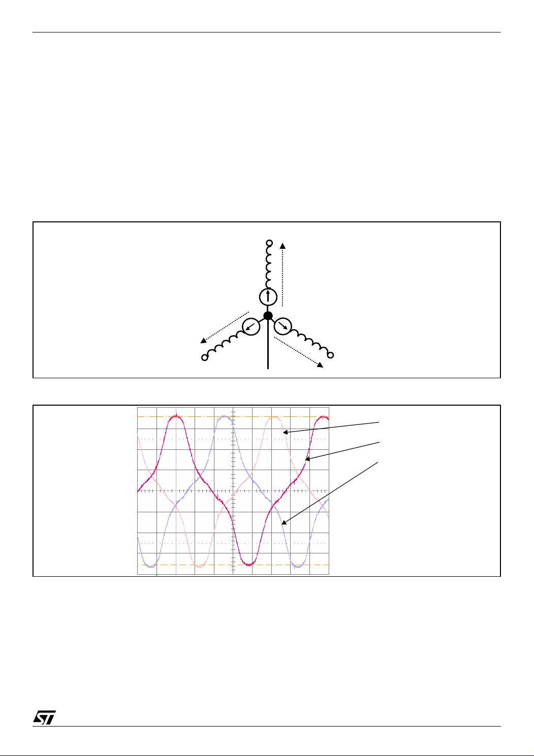
Figure 2 below shows the three BEMF voltages referenced to the neutral point for a motor run-
ning at constant speed without excitation (the motor is not supplied, and the rotor is manually
rotated).
Figure 1. Model of BLDC Motor with the Wire in Star Connection.
A
E
a
E
c
E
b
B
Neutral
C
Figure 2. Phase voltage versus Neutral For each stator winding
Ea
Eb
Ec
For a given fixed motor design (number of stator winding turns, mechanical rotor characteristics and rotor magnet characteristics) the BEMF Amplitude is proportional to the rotor speed.
The sensorless method uses the zero crossing of BEMF to synchronize phase commutations.
To detect BEMF the specific 120° six-step drive is used. "120° six-step drive" forces zero cur
rent twice in each phase during a six step period. This allows BEMF zero crossing to be detected and read.
-
3/35
Page 4
AN1946
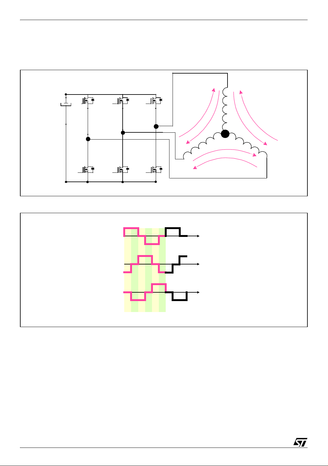
The step sequence and corresponding motor phase current are shown in Figure 3 and Figure
4 below.
Figure 3. Six-Step current circulation
+HV DC
T5
W
T6
-
Figure 4. Six-Step sequence
T3
V
T4
Current in winding A,B,C
A
T1
U
T2
1
6
4
5
A
B
C
2
3
t
B
C
1234
T1 T1 T3 T3 T5 T5
T4 T6 T6 T2 T2 T4
More specifically, for each step, one phase of the motor is not energized, which allows detection of the BEMF zero crossing in this phase.
For each phase two zero crossings must be detected during a period:
One "rising crossing" when BEMF passes from negative to positive,
One "falling crossing" when BEMF passes from positive to negative.
In the non-energized winding (phase C here), the current is zero and the voltage measured is
the BEMF of the motor (
4/35
Figure 5).
56
t
t
Page 5
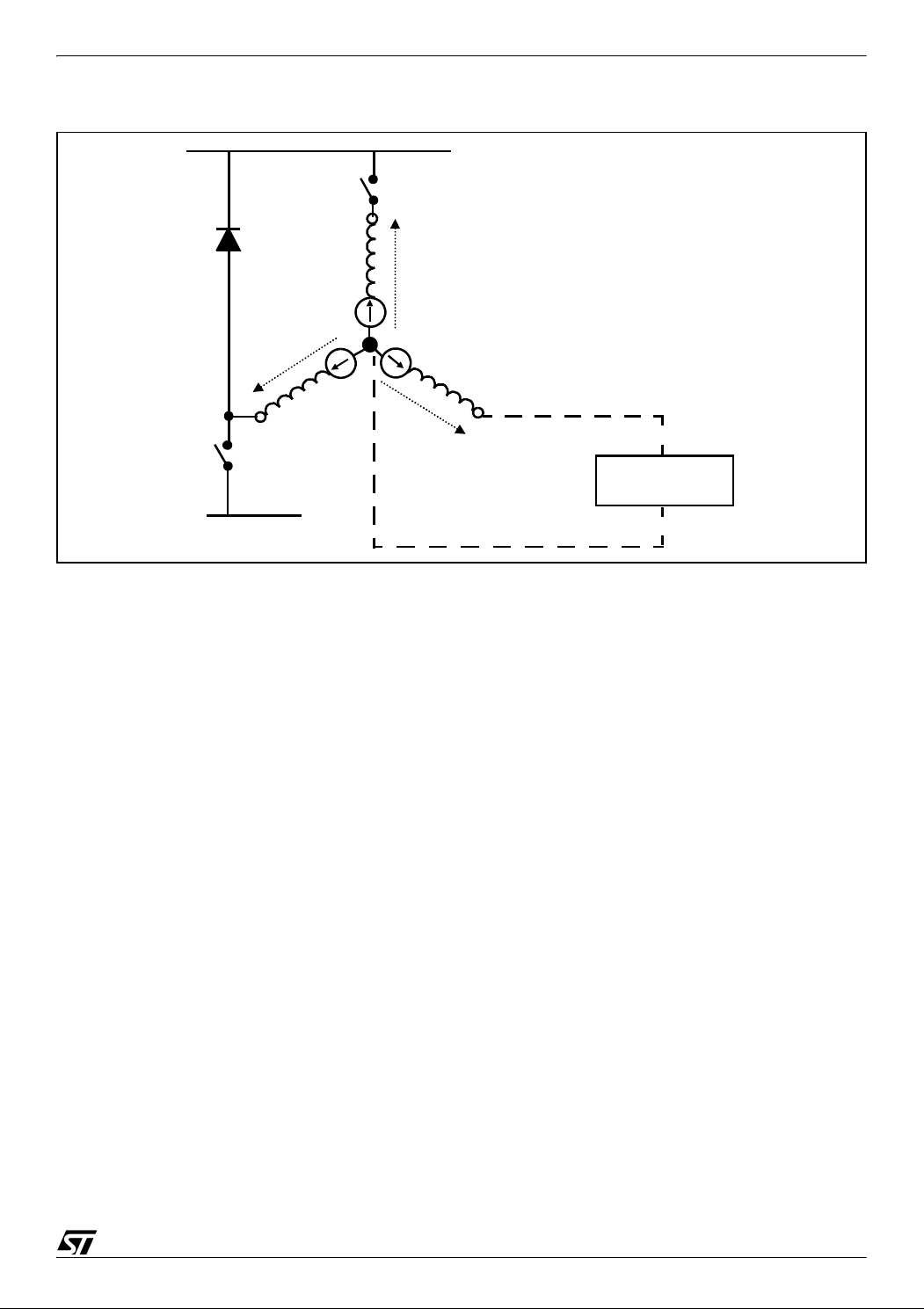
Figure 5. BEMF measurement synoptic.
A
e
a
e
c
AN1946
BUS
e
b
N
C
B
Voltmeter
POWER GND
Based on the above BEMF detection principle, several methods are available to precisely determine the BEMF zero crossing point. All these methods have advantages and drawbacks
which will be discussed in the next section. These methods also take into account the fact that
in most cases the neutral point of the motor is not accessible; either because the motor is
delta-wound, or because no wire is extracted. In any case the methods presented in the next
section allow the designer to select the most suitable approach to meet his application require
ments.
Note 1: Because BEMF is proportional to the rotor speed, this implies that the rotor should
turn at a minimum speed to generate sufficient BEMF. This minimum speed varies from one
motor to another. For very low speeds it may be required to amplify BEMF in order to control
the motor. This is presented in the appendix of this application note.
-
Note 2: As mentioned above, the sensorless BEMF methods described can only be implemented using a trapezoidal signal drive. A sine wave signal drive doesn't provide zero
crossing signals and cannot be implemented with the topologies shown above. It is to be
noted however that motors originally designed to be driven with a sine wave signal (these mo
tors are wound in such way that the stator flux has a continuous variation contrary to BLDC
wound motors which have non-continuous stator flux commutation) can be controlled with a
trapezoidal signal drive and ST7MC, without any impact on performance.
5/35
-
Page 6
AN1946
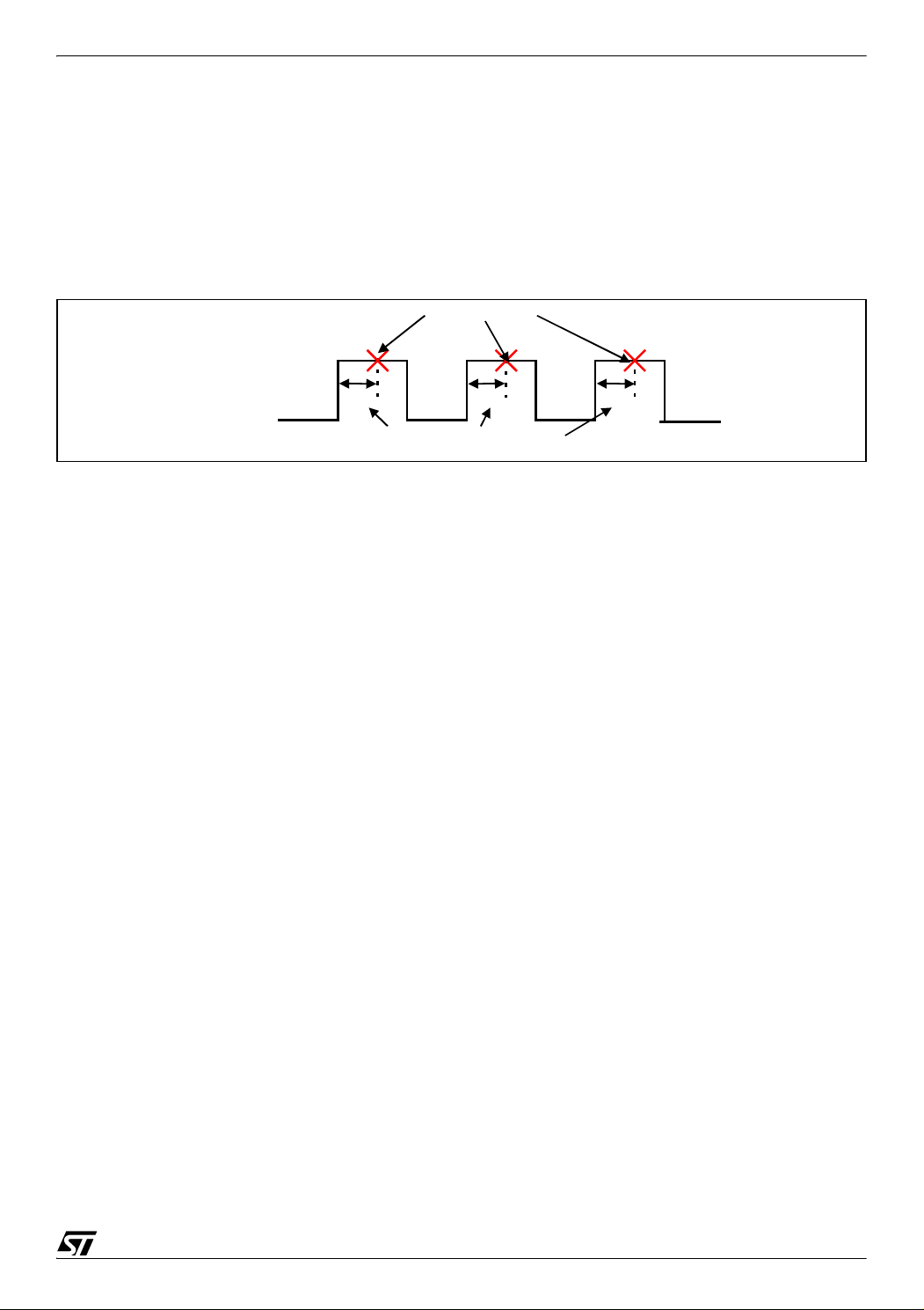
2.1 SAMPLING METHOD
The ST7MC microcontroller allows the implementation of four methods to sample and detect
BEMF zero crossing to run a BLDC motor in sensorless mode.
Sampling during PWM OFF State at PWM frequency (SPLG=0 & DS[3:0]=0)
“ON”
PWM signal
“OFF”
Sampling order
Sampling during PWM ON state only at PWM frequency (SPLG=0 & DS[3:0]=xxx)
Sampling order
“ON”
PWM signal
d
“OFF”
Programmable Delay
d
d
Sampling during PWM ON state only at High frequency (SPLG=1 & DS[3:0]=xxx)
sampling
“OFF”
f
SCF
d
d
PWM signal
“ON”
d
Programmable Delay
Sampling either during OFF or ON state at High frequency (SPLG=1 & DS[3:0]=0)
f
sampling
SCF
PWM signal
“ON”
“OFF”
These allow for various controls and hardware topologies to be implemented.
Each method is presented below with benefits, drawbacks and rules to select the right method
for a given motor/application.
6/35
Page 7
AN1946
3 SAMPLING AT END OF PWM OFF STATE (ST PATENTED "3 RESISTOR" METHOD)
3.1 DESCRIPTION
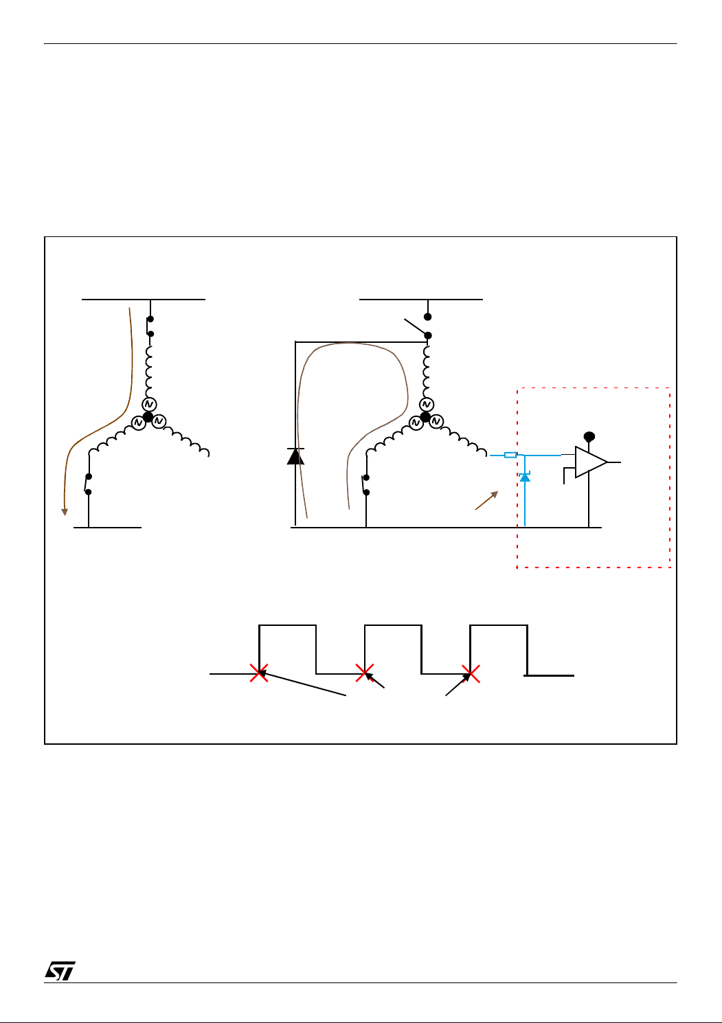
BEMF sampling is fully digital based on the PWM duty cycle. Figure 6 below gives the physical
configuration of a motor when PWM is in an OFF state allowing BEMF to be measured during
the non-energized phase.
Figure 6. BEMF sampling at end of PWM OFF
300V
T1 PWM "ON"
A
V/2
C
B
T4 always ON
GND
Current in A & B Phases
when T1 “ON”
bemf
PWM signal
D2
B
T4 always ON
GND
Current in A & B Phases
when T1 “OFF”
“ON”
“OFF”
300V
T1 PWM "OFF"
A
GND
C
bemf
voltage clamping
+ 5V
ST7MC
Sampling order
During the Off state of PWM, the current circulation in active winding of the motor passes
through D2, the adjacent diode of switch T1.
Due to the fact that the potential of the neutral point is grounded, the voltage comparator obtains complete information about the BEMF voltage of the non-energized phase on its input
via C. Application Note AN1130 gives more information about this sampling method.
7/35
Page 8
AN1946
Advantages:
To sample the BEMF of the BLDC motor, the ST patented method needs only three resistors
(to limit input current in I/O) as external components. This simplifies the practical implementa
tion which consists of connecting the three resistors from the three motor phases to the MCIA,
MCIB, and MCIC Microcontroller inputs which:
– allows the whole sensing signal for the BEMF to be obtained,
– gives high sensitivity, used to:
– Get a large speed range on the drive motor,
– Run the motor at very low speed,
– Start the motor with maximum torque
– avoids the need for an analog filter, which suppresses filtering delays
– provides high signal to noise ratio
Drawback:
A minimum PWM OFF time is needed and the maximum available duty cycle should be limited.
-
For some applications we need to go up to maximum (100%) duty cycle, this cannot be
reached with the ST detection method and we have to switch to the classical detection method
which is described later.
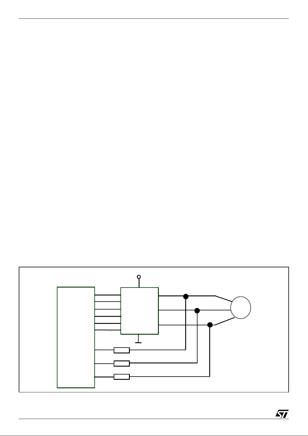
3.2 ST7MC-KIT/BLDC PRACTICAL IMPLEMENTATION
By default the ST7MC-Kit/BLDC starter kit board is configured to use the ST patented "3 resistors" method.
Figure 7. Sampling at end of PWM off implementation
V
DC
W
U
V
Motor
6_MCOx
ST7FMC
MCIA
MCIB
Three
Phase
Power
Converter
8/35
MCIC
Page 9

AN1946
The implemented resistors are used to limit the input current in the pad diode which clamps
the voltage on MCIA, MCIB and MCIC microcontroller inputs.
The current in the clamping diode should not exceed 5mA and should typically be around
2mA.
For a high voltage (400V) DC bus, 200k resistors are to be used. For safety and power dissipation, two 100k resistors in serial are implemented on each phase.
Resistors implemented on the starter kit board are two 82k which is suitable both for the 24V
motor included and also for high voltage motors.
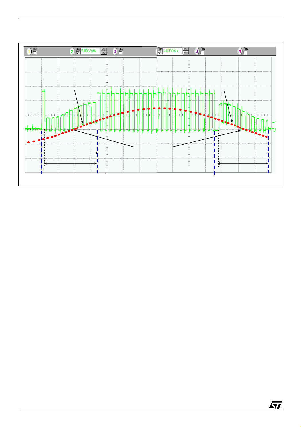
3.3 PRACTICAL RESULTS
The sampling below (Figure 8) shows the voltage signal on one phase of the motor drive in 6step mode.
During both steps where the phase is not energized, corresponding to the floating state of the
winding, we can follow the progression of BEMF:
For the "rising transition" between T1 & T2 where BEMF passes from a negative to
positive value;
For the "falling transition" between T4 & T5 where BEMF passes from a positive to
negative value.
We can note the PWM superposition with the BEMF signal for both "ON" and "OFF" states of
the PWM.
For compare values set to zero, we get the zero crossing information only when the PWM is
in an "OFF" state.
9/35
Page 10
AN1946
Figure 8. Sampling at end of PWM "OFF" state
Back-EMF
Back-EMF
Z ero C ro ssing
Z ero C ro ssing
Floating phase
Floating phase
Conducting phase
Conducting phase
T3
T1
T1
T2
T2
T3
Back-EMF
Back-EMF
Floating phase
Floating phase
T4
T4
T5
T5
The zero crossing detection can also be done when PWM is in an "ON" state if the compare
value is set to the half value of the DC bus. This sampling method is discussed in further detail
later.
The fact that a 100% PWM duty cycle cannot be achieved with this method may be a drawback when the motor needs to be used to the limit of its capabilities.
The main advantage of the "3 resistors method" is that, being fully digital it allows maximum
efficiency over a very wide speed range, typically 1 to 100.
Finally, the key advantage of this method is its cost which is the lowest available on the market
now.
10/35
Page 11
AN1946
4 SAMPLING DURING PWM ON STATE (INDUSTRY STANDARD “CLASSICAL” BEMF METHOD)
4.1 DESCRIPTION
In this configuration, due to sampling during PWM "ON" state, the neutral point is not
grounded like in the previous method.
Figure 9. Sampling during PWM “ON” State Once
Sampling order
“ON”
PWM signal
d
“OFF”
Programmable Delay
d
d
We have to get an access to this neutral point to be able to measure the BEMF voltage.
In many applications like compressor drives, it is not possible to implement a wire giving access to a neutral point. To get this voltage information we use various methods to rebuild a virtual neutral.
We can already note that both sampling methods during PWM ON (sample at PWM frequency
or sample at high frequency) can be implemented using:
– Discrete frozen analog filter build with resistor and capacitor, or
– Embedded digital filter of ST7MC.
The zero crossing of the BEMF measurement is done using an analog filter.
With this classical analog method the BEMF is detected through two networks.
One network is used to sense the BEMF on the floating phase and allow passing from a high
voltage level to a low voltage level compatible with the comparator input. The switching of the
PWM signal gets on the voltage adaptation request to be filter.
A second network allows the voltage reference of floating phase to be obtained necessary to
do the BEMF detection.
This second network could be realized following three schemas:
a) The rebuild of the virtual neutral motor using three resistors and again a voltage divider and
filter.
b) A voltage divider of High DC bus Voltage to get a reference voltage compatible with the
input voltage of the comparator (2.5V for example) and which follows the DC bus fluctuation.
c) In the event of constant DC bus without fluctuation, this second network can be removed
and be replaced by the internal reference voltage of the microcontroller comparator.
11/35
Page 12

AN1946
Figure 10 gives the implementation of the classical method using a voltage divider and filter.
Figure 10. Implementation of the Classical Method using a Voltage Divider and Filter
HV
N
N'
POWER GND
virtual ground
divider & filter
+ 5V
~
divider & filter
In the implementation using the Classical method, where for the observed phase we used a
voltage divider and filter, the reference voltage used can be either:
– The High Voltage DC bus, or
– The internal comparator Microcontroller reference as show in Figure 11.
Figure 11. Voltage reference on HV Bus or Internal voltage reference
HV
12/35
N
HV/2
POWER GND
divider & filter
+ 5V
~
Vref
divider & filter
Page 13

AN1946
Advantages
With the classical method, BEMF sampling is done during the PWM “ON” state allowing up to
a maximum PWM duty cycle (100%).
Drawbacks
Due to the voltage divider being used to sense BEMF, this method is less sensitive that the ST
method. This sampling method is dependent on the motor speed because the different net
works are influenced by BEMF levels and components are to be dimensioned according to the
nominal operation point of the motor.
4.2 PRACTICAL IMPLEMENTATION OF SAMPLING DURING PWM ON
The starter kit board is delivered with a daughter board allowing classical sampling method
use.
Figure 12 gives an example of network use to implement the classical method with an analog
filter.
Figure 12. Classical method of implementation with daughter board.
-
6_MCOx
MCIA
MCIB
MCIC
ST7FMC
MCVREF
R6
C2 C3
V
Three
Phase
Power
Converter
R4
R2
R11
DC
U
V
W
C4
R10
C1
R5
R3
R1
R7
R8
Motor
R9
13/35
Page 14

AN1946
4.2.1 Components dimensioning
The sizing of network components is mainly dependant on the speed due to the variable level
of BEMF. The following computations are done considering the zero value of the observed
BEMF when we are near of the zero crossing time.
Dimensioning the RC Networks
During the PWM "ON" state we have the following motor phase polarization:
Phase A and B of the motor conduct current and phase C is the floating phase on which we
can detect the BEMF.
An application running on mains (230Vac) is described, and control of the motor is done using
the PWM principle running at a fixed frequency (18.1 KHz).
The Voltage Reference can be built using the virtual neutral of the motor using three resistors
R7, R8 and R9, or using a voltage divider from the DC bus to be compatible with the input
voltage of the comparator (5V). Another way is to use the internal voltage reference of
ST7FMC and adapt the phase network divider to this voltage reference.
Figure 13. Two alternatives for virtual neutral rebuild
I phase
A
B
C
R8
R7
C1
R9
Vn
R10
MCVREF
R11
Motor
(a)
C1
V
DC
R
R10
R11
MCVREF
(b)
14/35
Page 15

AN1946
4.2.2 Size of Reference Voltage
a) The voltage level of virtual neutral Vn, for a mains application can be approximated to half
of the maximum DC bus.
V
DC
----------
V
n
2
325
-------- -162V===
2
We have to adapt the voltage level of virtual neutral to level acceptable by microcontroller. The
target here is to fix the voltage reference with which BEMF is compared to Half of Microcon
troller supply (5V).
The adaptation of the voltage is done with R10 & R11 resistors.
R10 = 270K and R11 = 3.9K gives
MCREF = 2.3V
The C1 capacitor allows filtering of the signal from the PWM drive of the motor.
At a PWM frequency of f =18.1 KHz the corresponding period is 55µs.
-
The equivalent resistor to R10 & R11 can be approximated to R11.
C1
-----------------------------------------= -> C12.2nF=
2
1
π×f×
R11
×()
With a coefficient of 10, this gives: C1= 22 nF
b) With a voltage divider on the DC bus, the voltage adaptation is done with R, R10 & R11 resistors.
The target here is to fix the reference voltage with which BEMF is compared to half of the Microcontroller supply (5V). So 2.5V corresponds to the value of the neutral point when PWM is
ON.
R = 120K, R10 = 270K and R11 = 2.7K which gives
MCREF = 2.49V
c) For the use of an internal reference voltage this is set to 2.5V.
4.2.3 Size of BEMF sensing network
For each motor winding we have an identical network (R1 & R2 for Phase C) allowing the
voltage to be adapted to the one acceptable by the microcontroller and again we need a ca
pacitor (C4) to filter the signal.
-
15/35
Page 16

AN1946
Figure 14. Analog Sampling Implementation
I phase
A
MCIC
C4
B
C
C1
R7
R8
R10
R11
R9
Vn
R1
R2
Motor
MCVREF
The sampling of BEMF is done during PWM ON, so the BEMF is centered on half of the DC
bus:
V
DC
----------
V
n
2
325
-------- -162V===
2
We have to adapt the voltage level of BEMF to the virtual neutral level already fixed to half of
the Microcontroller supply (5V).
This voltage adaptation is done with the R1 & R2 resistors.
R1 = 180K and R2 = 2.7K gives
MCIC = 2.3V if we consider a zero value for Ec BEMF.
The C4 capacitor allows filtering of the signal due to the PWM drive of the motor.
At a PWM frequency of f =18.1 KHz the corresponding period is 55µs.
The equivalent resistor to R1 & R2 can be approximated to R2.
C4
--------------------------------------= -> C43.2nF=
1
2 π× f× R2×()
With a coefficient of 10, the value is fixed for: C4= 27 nF which is the lower normalized value.
For the classical sampling method ST7FMC allows sampling to be made at the PWM "ON"
state after a programmable delay or PWM "ON" state at high frequency after a programmable
delay.
16/35
Page 17

AN1946
Samplings at high frequency during PWM "ON" avoids getting jitter due to PWM frequency on
the BEMF detection, and the Z event counter allows filtering during detection and rejection of
spurious information.
4.3 PRACTICAL IMPLEMENTATION OF THE "CLASSICAL" METHOD, USING THE ST7MC-KIT/ BLDC STARTER KIT
The ST7FMC starter kit board allows using a Daughter Board to run a BLDC motor using the
classical BEMF detection circuit.
The Daughter Board is plugged onto the J11, W14, W15 & W16 connectors of the starter kit
board as represented below.
Figure 15. Daughter Board place on Starter kit board
Microcontroller Phase
Input Connector
The photo in Figure 16 shows a daughter board using a virtual neutral rebuild plug on the
mother starter kit board.
17/35
Page 18

AN1946
Figure 16. Daughter Board Plug on Starter Kit Board
Daughter Board
Plug on Starter Kit Board
4.4 PRACTICAL RESULTS
The following two figures show waveforms of both virtual neutral and Phase voltages at the
input of the microcontroller for a motor running on mains.
The hardware end of the demagnetization detection is used and Z sampling is done during
PWM “ON”.
Figure 17 shows the observation of the demagnetization falling end event and the rising Zero
crossing event for BEMF.
18/35
Page 19

AN1946
Figure 17. Falling Demagnetization for Rising Zero crossing detection
Phase Current
Demagnetization Debug Signal
Virtual Neutral
Phase Voltage
D
CZ
Figure 18 shows the observation of the demagnetization rising end event and falling Zero
crossing event for BEMF.
Figure 18. Rising Demagnetization for falling Zero crossing detection
Phase Current
Zero Crossing Debug Signal
Virtual Neutral
Phase Voltage
CZ
D
19/35
Page 20

AN1946
5 SAMPLING DURING PWM ON STATE USING DIGITAL FILTER
5.1 DESCRIPTION
The ST7MC microcontroller allows implementation of sampling with its full digital filter during
PWM “ON” without an analog filter and is easier to network, to size and to implement.
Bits DS [3:0] of the MCONF register allow the configuration of the delay to be inserted before
sampling after PWM ON
Sampling of BEMF can be done once at each PWM ON or at high frequency. For both sampling methods, an event counter (using the ZEF [3:0] bits in the MZFR register) allows filtering
to avoid spurious detection.
In this method the BEMF of the observed phase is sampled during the PWM ON state.
Figure 19. Sampling during PWM “ON” state at high frequency
sampling
“ON”
f
SCF
PWM signal
d
“OFF”
Programmable Delay
d
d
We have to implement a voltage divider to take care of the neutral voltage when the BEMF
crosses the zero voltage. At this point, the zero voltage is centered on half of the DC bus.
Figure 20. Digital Sampling during PWM ON
HV
N
HV/2
divider
+ 5V
~
POWER GND
Vref
20/35
divider
Page 21

AN1946
Advantages
This method of BEMF sampling is done during PWM “ON” state allowing up to a maximum
duty cycle (100%). Use of high frequency sampling without analog filtering and with the possi
bility of digital filtering gives more flexibility to this method.
Drawbacks
This method is less sensitive than the ST method because the voltage divider is used to sense
BEMF.
5.2 PRACTICAL IMPLEMENTATION
The following schema shows the network for sampling during PWM ON using a digital filter implemented with the use of an external reference voltage following the DC bus variation.
The network on the DC bus used to realize the reference voltage can be removed in the situation where the DC bus is constant.
In its place we use the internal programmable reference (from 0.2V to 3.5V) of the ST7MC.
-
Figure 21. Digital PWM ON Sampling Implementation
V
DC
U
V
W
R5
R3
R1
R2
6_MCOx
MCIA
MCIB
MCIC
R6
Three
Phase
Power
Converter
R4
ST7FMC
R10
MCVREF
R11
Motor
21/35
Page 22

AN1946
5.2.1 Sizing of network on motor phase
On each motor winding, if we consider a zero value of the BEMF voltage for the observed
phase, we need a couple of resistors to pass the voltage from half of the DC bus to the level
chosen for the reference voltage.
Sampling of BEMF is done during PWM ON, so the BEMF is centered on half of the DC bus:
V
DC
----------
V
n
2
325
-------- -162V===
2
We have to adapt the voltage level of BEMF to the fixed reference voltage to be compatible
with the Microcontroller supply (5V).
Figure 22. Network on Observed Phase
I phase
A
B
C
R1
MCIC
R2
This voltage adaptation is done with R1 & R2 resistors.
R1 = 164K and R2 = 2.2K gives
motor
MCIC = 2.1V if we consider a nil value for ec BEMF.
22/35
Page 23

AN1946
5.2.2 Sizing of Network of Voltage Reference
The voltage comparator of ST7MC needs a voltage reference corresponding to the potential
of motor phase winding common neutral point and equal to half of DC bus.
This voltage reference corresponds to the network sizing calculation on the motor phase
(2.1V).
Figure 23. Network for Voltage Reference
V
DC
R10
MCVREF
R11
This voltage reference is built from the power converter DC bus to manage of any variation.
For the main application the DC bus is equal to 325V.
The voltage divider allows the voltage to pass from the DC bus (325V) to the determined
voltage reference (2.1V).
This voltage adaptation is made with R10 & R11 resistors.
R10 = 180K and R11 = 1.2K giving
MCVREF = 2.15V
If we have a stable DC bus, the internal voltage reference of ST7MC can be used and in this
case is set to 2V.
23/35
Page 24

AN1946
5.3 RECORDS OF DIGITAL SAMPLING DURING PWM ON
The figures below show sampling during PWM ON with a digital filter.
Figure 24. Rising BEMF sampling during PWM ON Vref=2V
C
Z
MCZEM Zero Crossing Debug Output
Phase Motor Current
Voltage Comparator Input
Figure 25. Falling BEMF sampling during PWM ON Vref=2V
C
Z
24/35
MCZEM Zero Crossing Debug Output
Phase Motor Current
Voltage Comparator Input
Page 25

AN1946
6 MIXED SAMPLING AT END OF PWM OFF AND DURING PWM ON
Sampling at the end of PWM OFF limits the duty cycle and hence does not allow 100% of the
duty cycle on the motor.
Sampling during PWM ON needs a minimum ON state to be able to do sampling, so this can
be a limitation in case of a low load of the motor.
For both sampling methods there is a limitation.
We can use the features of ST7MC passing from one sampling method to the other, covering
all the PWM states.
The solution we present here proposes to start the motor using sampling at the end of PWM
OFF allowing the motor to be run with a short PWM On and at low speed.
The BEMF sampling at PWM OFF needs only a serial resistor between the motor winding and
the input voltage comparator of the microcontroller.
The sampling during PWM ON needs a voltage divider to get a voltage level compatible with
the input of the voltage comparator.
The software driver of a classical I/O of a microcontroller used to drive the switch to enable a
voltage divider on each input of the voltage comparator allows one configuration to pass to the
other without perturbation of signal when sampling is done at end of PWM "OFF".
25/35
Page 26

AN1946
Figure 26. Mixed PWM state Sampling Implementation
V
DC
6_MCOx
MCIA
MCIB
MCIC
ST7FMC
PB
MCVREF
Three
Phase
Power
Converter
R4
R6
R2
R11
W
U
V
R5
R3
R1
R10
Motor
The application note AN2030 gives more detail on this mixed method allowing the motor to be
run from low PWM ON state to 100% PWM duty cycle.
Advantages
With this mixed method of BEMF sampling, we keep the high sensitivity of the ST method
based on sampling at the end of PWM "OFF" state for low speed where BEMF is low and we
can run the motor at maximum speed using sampling during PWM "ON" state allowing up to
a maximum PWM duty cycle (100%). Use of high frequency sampling without analog filtering
and with possibility of digital filter gives more flexibility to this method.
Drawbacks
Due to the voltage divider used to sense BEMF during PWM "ON" state we have less sensitivity than for sampling at the end of PWM "OFF" state.
26/35
Page 27

AN1946
7 BEMF SAMPLING AT HIGH FREQUENCY METHOD (USED IN PULSE AMPLITUDE MODULATION METHOD)
The ST7FMC allows BEMF sampling at High Frequency whatever the PWM state. This sampling is useful in applications where the Pulse Amplitude Modulation (PAM) is used.
In this case, a PWM signal is used to monitor the level of the DC voltage bus using a DC/DC
converter and motor commutations are done using a pure 6-step signal.
The sampling of BEMF is done permanently at high frequency on the non-energized phase.
This method allows the reduction in the switching noise of power converters due to the pure 6step drive.
8 CHOICE OF SAMPLING METHOD
The Table below lists the main features of different possible sampling methods with ST7MC:
N°
1
2
3
4
5 High frequency
Sampling
Method
End of PWM
"OFF"
Classic PWM
"ON"
PWM "ON" High
Frequency
Mixed PWM
"ON" and PWM
"OFF"
Strong point Weak point Comment
High Sensitivity
Allow 100% PWM
duty cycle
Allow 100% PWM
duty cycle, use of
digital filter
High Sensitivity at
low speed and
100% PWM
Independent of
PWM state
No 100% PWM
duty cycle
Analog Filter, Minimum on state
Minimum on state
Use additional I/O
and management
of speed transition
Need a specific
management of
DC bus
Preferable method where 100%
duty cycle of PWM is not needed.
Motor speed dependent due to
use of analog filter
If 100% duty cycle is needed and
no request for low speed this
method is preferable
Best method if 100% duty cycle is
needed and request of low speed
drive
Dedicated to applications where
switching noise of power convert
er is not acceptable.
-
Due to powerful digital features of ST7MC the classical method (n°2) can be eliminated. The
high frequency sampling method (n°5) is dedicated to specific applications and cannot be con
sidered for appliance applications like compressors, pumps, etc.
So this kind of sampling method application must be chosen between 1, 3 or 4.
-
The PWM duty cycle and the application speed range are the key parameters to select the
well adapted sampling method.
27/35
Page 28

AN1946
9 CONCLUSION
In these days where inverter technology and permanent magnet motors are increasingly used
in automotive, appliance and industrial applications, ST7MC offers a unique advantage; in
conjunction with leading edge development tools, it allows any developer the chance to eval
uate and choose the most suitable control method for his motor application.
Whatever the method chosen, ST7MC keeps system costs as low as possible, and maintains
the highest standards of performance.
-
28/35
Page 29

AN1946
10 APPENDIX - IMPROVED BEMF DETECTION FOR LOW SPEED AND LOW VOLTAGE APPLICATIONS
10.1 THEORY
If phase A and B are conducting current, phase C is floating. The terminal voltage Vc is detected.
Vdc
L
GND
Va
Vd
r
r
Vb
Vb
r
r
Vc
Vc
Vmos
i
i
L
L
e
e
e
a
b
Vn
c
5V
5V
5V
5V
Vref
Vref
ST7MC
Micro controller
5V
5V
5V
5V
When the top transistor is turned off, the current freewheels through the diode D. During this
freewheeling period, the terminal voltage Vc is detected as Phase C BEMF because there is
no current in phase C.
In fact, vc = ec + vn. Only when Vn equals zero, Vc is the Back EMF. As matter of fact, Vn is
always non-zero.
From phase A, we have
di
v
0 vd– ri– L
n
---- -
– ea–= (1)
dt
From phase B, we have
di
---- -
v
v
n
mos
ri L
Where Vd is the forward voltage drop of the diode, V
e
–++= (2)
b
dt
is the voltage drop on MOSFET.
mos
Adding (1) and (2), we get
2v
n
v
n
v
– eaeb+()–= (3), and
mosvd
v
mosvd
---------------------2
e
–
aeb
----------------–= (4)
+
2
29/35
Page 30

AN1946
Also from the balance three-phase system, we have
eaebe
++ 0= (5)
c
From (3) and (4),
v
v
n
–
mosvd
---------------------2
e
c
----–= (6)
2
So, the terminal voltage Vc,
v
3
-- -
v
ecv
c
+
e
n
c
2
–
mosvd
----------------------+== (7)
2
If we ignore the second term of (6), the terminal voltage is the Back EMF. However, at low
speed and low voltage, the Back EMF itself is very small, the second term will play a signifi
cant role here. For low voltageMOSFET, Rd is very low, Vmos can be ignored, so (6) can be
rewritten as,
v
3
v
ecv
c
+
-- -
n
2
e
---- -–== (8)
c
2
d
-
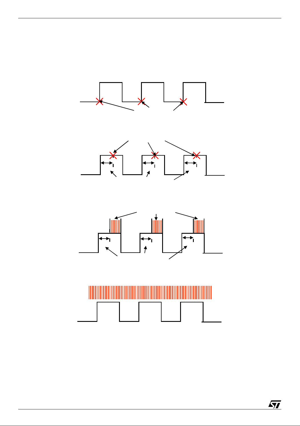
10.2 PROBLEMS
(a). As mentioned before, the voltage drop on the diode will affect the Back EMF significantly
when the Back EMF is low. Theoretically, zero-crossing is evenly distributed each 60 electric
degree. But because of the diode voltage drops, this will cause the zero-crossing to be unsym
metrically distributed.
Figure 27 shows the simulation result.
Figure 27. Simulation result shows the zero-crossing is unsymmetrical
4
4
4
2.3
2.3
2.3
2
2
2
0
0
0
A1x()
A1x()
A1x()
B1x()
B1x()
B1x()
2
2
2
C1x()
C1x()
C1x()
D1x()
D1x()
D1x()
4
4
4
6
6
6
Zero-crossing
8−
8−
8−
8
8
8
01102203304405506607708809901100
01102203304405506607708809901100
01102203304405506607708809901100
Zero-crossing
Figure 28 shows the testing result.
-
30/35
Page 31

AN1946
Figure 28. Test result shows the zero-crossing is unsymmetrical
Zero-crossing signalZero-crossing signal
The wrong zero detection will cause wrong commutation which probably will stall the motor.
Also bad zero-crossing will cause bad speed regulation.
(b). At low voltage or low speed, the zero-crossing slope is very flat. The offset and the hysteresis loop of the comparator will cause the bad zero-crossing detection. Meanwhile, because of
the low Back EMF, it is very susceptible to the noise.
10.2.1 Solution
To solve the first problem, we need to eliminate the effect of diode voltage drop. Adding another constant voltage before the voltage signal is sent to the comparator can eliminate the effect of the diode.
To solve the second problem, we need to sharpen the slope of the Back EMF during the zero
crossing period. We can use an amplifier to amply the Back EMF signal only around zero
crossing time because we are not interested in other time periods.
Figure 29 shows the solution.
Figure 29. Solution to improve BACK EMF detection
GND
GND
15V
15V
Va,b,c
Va,b,c
VconrR1
VconrR1
R2
R2
r
r
E
E
TS274
TS274
Rf
r
r
Rf
31/35
Page 32

AN1946
TS274 is a high speed Op-amp. Choose R1 and R2 such that VconR1/(R1+R2)=Vd/2.
The positive input of the Op-amp is clamped at 0.7v by a diode because we are only interested
in the zero crossing. So we only sharpen the slope of the back EMF near the zero crossing.
10.3 RESULT
0.5v/div
0.5v/div
0.5v/div
A
A
5v /d iv
5v /d iv
5v /d iv
B
B
Ze ro-cro ssing
Ze ro-cro ssing
Ze ro-cro ssing
The green channel (top) is the signal directly from the winding, the terminal voltage,0.5v/div.
The back EMF signal is very weak. Point A will be the zero-crossing point.
The pink channel (middle) is the output from the Op-amp, 5v/div. Point B is the zero-crossing
point.
Because of the diode forward voltage drop, at the real zero-crossing point, the terminal
voltage is negative.
32/35
Page 33

The amplification makes the slope very sharp.
Now, the zero crossing signal is in very good shape.
10.4 CONCLUSION
Back E MF
Back E MF
Zero-crossing signal
Zero-crossing signalZero-crossing signal
AN1946
The theory clearly explains the mechanism of the Back EMF detection and shows the drawback of the original detection method.
The preconditioning circuit not only eliminates the effect of the diode forward voltage drop, but
also sharpens the slope of the Back EMF during the zero crossing period.
This circuit can greatly improve the performance of sensorless BLDC drive in low voltage applications, especially automotive. With this technique, the sensorless driver can be used with
a much wider speed range. For example, using the original detection method, the speed range
can only be 30-150 rpm. Using the improved method, the speed range can be 3-150rpm.
33/35
Page 34

AN1946
11 REVISION HISTORY
Table 1. Document revision history
Date Revision Changes
10-Jan-2005 1 Initial release
12-Jul-2007 2 Removed references to obsolete products
34/35
Page 35

AN1946
Please Read Carefully:
Information in this document is provided solely in connection with ST products. STMicroelectronics NV and its subsidiaries (“ST”) reserve the
right to make changes, corrections, modifications or improvements, to this document, and the products and services described herein at any
time, without notice.
All ST products are sold pursuant to ST’s terms and conditions of sale.
Purchasers are solely responsible for the choice, selection and use of the ST products and services described herein, and ST assumes no
liability whatsoever relating to the choice, selection or use of the ST products and services described herein.
No license, express or implied, by estoppel or otherwise, to any intellectual property rights is granted under this document. If any part of this
document refers to any third party products or services it shall not be deemed a license grant by ST for the use of such third party products
or services, or any intellectual property contained therein or considered as a warranty covering the use in any manner whatsoever of such
third party products or services or any intellectual property contained therein.
UNLESS OTHERWISE SET FORTH IN ST’S TERMS AND CONDITIONS OF SALE ST DISCLAIMS ANY EXPRESS OR IMPLIED
WARRANTY WITH RESPECT TO THE USE AND/OR SALE OF ST PRODUCTS INCLUDING WITHOUT LIMITATION IMPLIED
WARRANTIES OF MERCHANTABILITY, FITNESS FOR A PARTICULAR PURPOSE (AND THEIR EQUIVALENTS UNDER THE LAWS
OF ANY JURISDICTION), OR INFRINGEMENT OF ANY PATENT, COPYRIGHT OR OTHER INTELLECTUAL PROPERTY RIGHT.
UNLESS EXPRESSLY APPROVED IN WRITING BY AN AUTHORIZED ST REPRESENTATIVE, ST PRODUCTS ARE NOT
RECOMMENDED, AUTHORIZED OR WARRANTED FOR USE IN MILITARY, AIR CRAFT, SPACE, LIFE SAVING, OR LIFE
SUSTAINING APPLICATIONS, NOR IN PRODUCTS OR SYSTEMS WHERE FAILURE OR MALFUNCTION MAY RESULT IN
PERSONAL INJURY, DEATH, OR SEVERE PROPERTY OR ENVIRONMENTAL DAMAGE. ST PRODUCTS WHICH ARE NOT
SPECIFIED AS "AUTOMOTIVE GRADE" MAY ONLY BE USED IN AUTOMOTIVE APPLICATIONS AT USER’S OWN RISK.
Resale of ST products with provisions different from the statements and/or technical features set forth in this document shall immediately void
any warranty granted by ST for the ST product or service described herein and shall not create or extend in any manner whatsoever, any
liability of ST.
ST and the ST logo are trademarks or registered trademarks of ST in various countries.
Information in this document supersedes and replaces all information previously supplied.
The ST logo is a registered trademark of STMicroelectronics. All other names are the property of their respective owners.
© 2007 STMicroelectronics - All rights reserved
STMicroelectronics group of companies
Australia - Belgium - Brazil - Canada - China - Czech Republic - Finland - France - Germany - Hong Kong - India - Israel - Italy - Japan -
Malaysia - Malta - Morocco - Singapore - Spain - Sweden - Switzerland - United Kingdom - United States of America
www.st.com
35/35
 Loading...