

Page 1

AN1905
APPLICATION NOTE
ST7MC THREE-PHASE BLDC MOTOR CONTROL
SOFTWARE LIBRARY
INTRODUCTION
This application note describes one of the software libraries available for the ST7MC MCU.
The ST7MC microcontroller comes with a dedicated motor control cell (MTC) and can drive
both permanent magnet DC/AC motors (PMDC/PMAC also called BLDC) and induction AC
motors. This application note describes the ST7MC software library required to control a
BLDC motor with a trapezoidal 6-step drive in sensor or sensorless mode, open or closed
loop, and in current or voltage mode. The control of a PMAC motor in Sinewave mode with
sensors is detailed in application note AN1947. The control of an AC induction motor in Sinewave mode is detailed in application note AN1904.
The library is made of different C modules, compatible with both COSMIC
(www.cosmic-software.com) and METROWERKS (www.metrowerks.com) toolchains. The
functions are grouped into several families, making this library an easy way to go through any
BLDC project development. Used in conjunction with the ST7MC starter kit
(ST7MC-BLDC-KIT), evaluation can be achieved in a very short time, as the library eliminates
the need to study the MCU in detail.
A basic knowledge of C Language, PMDC motor drives and power inverter hardware is required.
AN1905 Rev 2 1/77
1
Page 2

Table of Contents
INTRODUCTION . . . . . . . . . . . . . . . . . . . . . . . . . . . . . . . . . . . . . . . . . . . . . . . . . . . . . . . 1
OVERALL SOFTWARE ARCHITECTURE . . . . . . . . . . . . . . . . . . . . . . . . . . . . . . . . . . 5
1 GETTING STARTED WITH TOOLS . . . . . . . . . . . . . . . . . . . . . . . . . . . . . . . . . . . . . . . 7
1.1 WORKING ENVIRONMENT . . . . . . . . . . . . . . . . . . . . . . . . . . . . . . . . . . . . . . . . . 7
1.2 SOFTWARE TOOLS . . . . . . . . . . . . . . . . . . . . . . . . . . . . . . . . . . . . . . . . . . . . . . 7
1.2.1 PROGRAMMERS . . . . . . . . . . . . . . . . . . . . . . . . . . . . . . . . . . . . . . . . . . . . . . . . . . . 7
1.2.2 Emulators . . . . . . . . . . . . . . . . . . . . . . . . . . . . . . . . . . . . . . . . . . . . . . . . . . . . . . . . . . 8
1.3 LIBRARY SOURCE CODE . . . . . . . . . . . . . . . . . . . . . . . . . . . . . . . . . . . . . . . . . 9
1.3.1 Download . . . . . . . . . . . . . . . . . . . . . . . . . . . . . . . . . . . . . . . . . . . . . . . . . . . . . . . . . . 9
1.3.2 File structure . . . . . . . . . . . . . . . . . . . . . . . . . . . . . . . . . . . . . . . . . . . . . . . . . . . . . . . 9
1.4 UTILITIES . . . . . . . . . . . . . . . . . . . . . . . . . . . . . . . . . . . . . . . . . . . . . . . . . . . . . . 10
1.4.1 lib.h file . . . . . . . . . . . . . . . . . . . . . . . . . . . . . . . . . . . . . . . . . . . . . . . . . . . . . . . . . . . 10
2 CUSTOMIZING THE WORKSPACE FOR YOUR ST7MC DERIVATIVE . . . . . . . . . 11
2.1 USING STVD7 RELEASE 2.5.X . . . . . . . . . . . . . . . . . . . . . . . . . . . . . . . . . . . . . 11
2.1.1 Memory mapping with the COSMIC toolchain . . . . . . . . . . . . . . . . . . . . . . . . . . . . . 11
2.1.2 Memory mapping with the METROWERKS toolchain . . . . . . . . . . . . . . . . . . . . . . . 12
2.2 USING STVD7 RELEASE 3.X.X . . . . . . . . . . . . . . . . . . . . . . . . . . . . . . . . . . . . 12
2.3 "VERSION.H" FILE . . . . . . . . . . . . . . . . . . . . . . . . . . . . . . . . . . . . . . . . . . . . . . 14
2.4 ADDITIONAL OR UP-TO-DATE TECHNICAL LITERATURE . . . . . . . . . . . . . . 15
3 GETTING STARTED WITH THE LIBRARY USING THE ST7MC-KIT/BLDC . . . . . . 16
3.1 INTRODUCTION . . . . . . . . . . . . . . . . . . . . . . . . . . . . . . . . . . . . . . . . . . . . . . . . 16
3.2 RUNNING THE MOTOR . . . . . . . . . . . . . . . . . . . . . . . . . . . . . . . . . . . . . . . . . . . 16
3.3 STANDALONE MODE AND CLOSED LOOP OPERATION . . . . . . . . . . . . . . . 18
3.4 NOTE ON DEBUGGING TOOLS . . . . . . . . . . . . . . . . . . . . . . . . . . . . . . . . . . . . 19
3.4.1 Low voltage applications (below 30V) . . . . . . . . . . . . . . . . . . . . . . . . . . . . . . . . . . . 19
3.4.2 Medium-high voltage application (above 30V) . . . . . . . . . . . . . . . . . . . . . . . . . . . . . 20
3.5 USING YOUR OWN POWER STAGE . . . . . . . . . . . . . . . . . . . . . . . . . . . . . . . . 21
3.6 CHECKING THE CURRENT SENSOR RESISTOR VALUE . . . . . . . . . . . . . . . 21
3.6.1 Maximum current . . . . . . . . . . . . . . . . . . . . . . . . . . . . . . . . . . . . . . . . . . . . . . . . . . . 22
3.6.2 Interpreting the current feedback/settings in the GUI . . . . . . . . . . . . . . . . . . . . . . . 23
2/77
1
77
Page 3

Table of Contents
4 MODULES PRESENTATION, LIBRARY ROUTINES . . . . . . . . . . . . . . . . . . . . . . . . 25
4.1 LIBRARY REFERENCES . . . . . . . . . . . . . . . . . . . . . . . . . . . . . . . . . . . . . . . . . 25
4.2 MTC SOFTWARE LAYER . . . . . . . . . . . . . . . . . . . . . . . . . . . . . . . . . . . . . . . . . 25
4.2.1 List of available routines . . . . . . . . . . . . . . . . . . . . . . . . . . . . . . . . . . . . . . . . . . . . . 26
4.2.2 List of MTC interrupt routines . . . . . . . . . . . . . . . . . . . . . . . . . . . . . . . . . . . . . . . . . . 36
4.3 APPLICATION LAYER . . . . . . . . . . . . . . . . . . . . . . . . . . . . . . . . . . . . . . . . . . . 45
4.3.1 regul.c . . . . . . . . . . . . . . . . . . . . . . . . . . . . . . . . . . . . . . . . . . . . . . . . . . . . . . . . . . . 45
4.3.2 adc.c . . . . . . . . . . . . . . . . . . . . . . . . . . . . . . . . . . . . . . . . . . . . . . . . . . . . . . . . . . . . 45
4.3.3 it_ST7MC.c . . . . . . . . . . . . . . . . . . . . . . . . . . . . . . . . . . . . . . . . . . . . . . . . . . . . . . . 46
4.3.4 ports.c . . . . . . . . . . . . . . . . . . . . . . . . . . . . . . . . . . . . . . . . . . . . . . . . . . . . . . . . . . . 47
4.3.4.1 Push button reading . . . . . . . . . . . . . . . . . . . . . . . . . . . . . . . . . . . . . . . . . 47
4.3.4.2 LEDs . . . . . . . . . . . . . . . . . . . . . . . . . . . . . . . . . . . . . . . . . . . . . . . . . . . . . 47
4.3.5 spi.c . . . . . . . . . . . . . . . . . . . . . . . . . . . . . . . . . . . . . . . . . . . . . . . . . . . . . . . . . . . . . 47
4.3.6 LinSCI.c . . . . . . . . . . . . . . . . . . . . . . . . . . . . . . . . . . . . . . . . . . . . . . . . . . . . . . . . . . 48
5 HOW TO DEFINE AND ADD A MODULE (STVD7 2.5.X) . . . . . . . . . . . . . . . . . . . . . 49
5.1 COSMIC TOOLCHAIN . . . . . . . . . . . . . . . . . . . . . . . . . . . . . . . . . . . . . . . . . . . . 49
5.2 METROWERKS TOOLCHAIN . . . . . . . . . . . . . . . . . . . . . . . . . . . . . . . . . . . . . . 50
6 CODE EXAMPLE . . . . . . . . . . . . . . . . . . . . . . . . . . . . . . . . . . . . . . . . . . . . . . . . . . . . 51
7 PMDC (PMAC) MOTOR CONSIDERATIONS . . . . . . . . . . . . . . . . . . . . . . . . . . . . . . 53
7.1 PHYSICAL CONSIDERATIONS . . . . . . . . . . . . . . . . . . . . . . . . . . . . . . . . . . . . 53
7.1.1 Checking the number of pair poles of the motor . . . . . . . . . . . . . . . . . . . . . . . . . . . 53
7.1.2 Connecting the sensor outputs to the board . . . . . . . . . . . . . . . . . . . . . . . . . . . . . . 54
7.2 CONTROL STRATEGY CONSIDERATIONS . . . . . . . . . . . . . . . . . . . . . . . . . . 55
7.2.1 Voltage versus current mode . . . . . . . . . . . . . . . . . . . . . . . . . . . . . . . . . . . . . . . . . . 55
7.2.2 Choosing a demagnetization type (Sensorless mode only) . . . . . . . . . . . . . . . . . . . 56
7.2.3 The 4 Z event sampling methods (Sensorless) . . . . . . . . . . . . . . . . . . . . . . . . . . . . 57
7.2.3.1 At the end of the PWM low state . . . . . . . . . . . . . . . . . . . . . . . . . . . . . . . 57
7.2.3.2 At PWM On, with delay once . . . . . . . . . . . . . . . . . . . . . . . . . . . . . . . . . . 58
7.2.3.3 At PWM On, with delay, at fSCF frequency . . . . . . . . . . . . . . . . . . . . . . . 58
7.2.3.4 At fSCF frequency . . . . . . . . . . . . . . . . . . . . . . . . . . . . . . . . . . . . . . . . . . 58
7.2.3.5 Conclusion . . . . . . . . . . . . . . . . . . . . . . . . . . . . . . . . . . . . . . . . . . . . . . . . 59
7.2.4 Setting the PWM distribution . . . . . . . . . . . . . . . . . . . . . . . . . . . . . . . . . . . . . . . . . . 59
7.3 SOFTWARE SETTING CONSIDERATIONS . . . . . . . . . . . . . . . . . . . . . . . . . . . 67
7.3.1 PI regulator implementation and tuning . . . . . . . . . . . . . . . . . . . . . . . . . . . . . . . . . . 67
7.3.2 Adjusting falling/rising Bemf settings . . . . . . . . . . . . . . . . . . . . . . . . . . . . . . . . . . . . 74
7.3.3 Completion of Fine Tuning and Other Software Considerations . . . . . . . . . . . . . . . 75
3/77
Page 4

Table of Contents
8 REVISION HISTORY . . . . . . . . . . . . . . . . . . . . . . . . . . . . . . . . . . . . . . . . . . . . . . . . . 76
4/77
1
Page 5

ST7MC THREE-PHASE BLDC MOTOR CONTROL SOFTWARE LIBRARY
OVERALL SOFTWARE ARCHITECTURE
APPLICATION LAYER
PI
REGULATION
WDG
PMDC MOTOR DRIVE
I/Os
PWM outputs
MCO[0..5]
MTC
MCES
MCIx (Optional hall effect sensors)
ADC
COMMUNICATION
PROTOCOL
LIN
SCI
SPI
16-bit
Timer
ST7MC Library Version 1.0 Characteristics (CPU running at 16 MHz)
- BLDC (trapezoidal 6 step method) modes available:
1.Sensorless : Back EMF voltage on the non-energized phase is monitored and used to
trigger the commutation events
Sensor : Hall effect sensors trigger the commutation events.
2.Voltage : PWM duty cycle is set directly via 12-Bit PWM Generator.
Current : Internal current loop and external voltage reference are used conjointly to set
the maximum current in motor windings. PWM duty is automatically set according to current feedback loop output.
3.Open loop operation.
Closed loop operation : PI regulation, 1 to 255 ms sampling time.
- 12-bit PWM generation frequencies:
Current mode, Voltage mode: fixed 390Hz, 625Hz, 961Hz, 1.25Khz, 1.56Khz, 3.13Khz,
6.25Khz, 10Khz, 12.5Khz, 15.4Khz, 18.1Khz, 20Khz, 25Khz, 33.33Khz, 40Khz, 50Khz.
(Voltage mode PWM frequency can be manually adjusted up to 50Khz in the library)
5/77
Page 6

ST7MC THREE-PHASE BLDC MOTOR CONTROL SOFTWARE LIBRARY
- Required ROM/RAM:
ROM (bytes) RAM (bytes)
Cosmic 4.5A Metrowerks 1.1 Cosmic 4.5A Metrowerks 1.1
Sensorless open loop 3400 4500 100 115
Sensorless closed loop 4700 6000 130 150
Sensor open loop 2370 3200 85 90
Sensor closed loop 3500 4600 120 125
These metrics include non motor control related code, implemented for demo purposes (such
as ADC management, software time bases, etc.). Depending on the chosen memory model,
the code size produced can be smaller or larger. This must therefore be considered only as indicative figures.
6/77
Page 7

ST7MC THREE-PHASE BLDC MOTOR CONTROL SOFTWARE LIBRARY
1 GETTING STARTED WITH TOOLS
1.1 WORKING ENVIRONMENT
The present software library was fully validated using the main hardware board (a complete inverter and control board) included in ST7MC-KIT/BLDC starter kit. The ST7MC-KIT/BLDC
starter kit also includes a low-cost INDART hardware debugger, making this tool an ideal set
for starting a project and evaluating/using the library.
Therefore, for rapid implementation and evaluation of the software discussed in this application note, it is recommended to acquire the ST7MC-KIT/BLDC starter kit and one of the two
compatible C-toolchains.
1.2 SOFTWARE TOOLS
This library has been compiled using COSMIC and Metrowerks C-toolchains, running under
STVD7 release 2.5.4 (ST Visual Debugger) and STVD7 release 3.x.x. Free IDE and demo
versions of third party toolchains can be found at http://www.st.com/mcu/ (then select Downloads). A complete software package consists of:
- An IDE interface: STVD7 (free download available on internet), or third party IDE (e.g.
SOFTEC Indart STX for ST7).
- A third party C-compiler: either Cosmic or Metrowerks (if needed, time-limited evaluation versions can be obtained upon request. A free 4K COSMIC version can compile all stand alone
firmware configurations).
The choice of the C Toolchain is left to the appreciation of the user. Both COSMIC and
METROWERKS are fully supported, and the dedicated workspace (compatible with ‘STVD7’
and ‘STVD7 for Indart’) can be directly opened in the root of the library installation folder
(BLDC_Sensorless_Metrowerks_STVD2_5_4.wsp,BLDC_Sensorless_Cosmic_STVD2_5_4.
wsp,BLDC_Sensor_Metrowerks_STVD3_x.wsp, BLDC_Sensor_Cosmic_STVD3_x.wsp).
In addition, the GUI included in the ST7MC-KIT/BLDC starter-kit allows customization of these
libraries with variables prepared for your own motor. This makes the first implementation of
this library significantly easier. See Section 3 of this document.
1.2.1 PROGRAMMERS
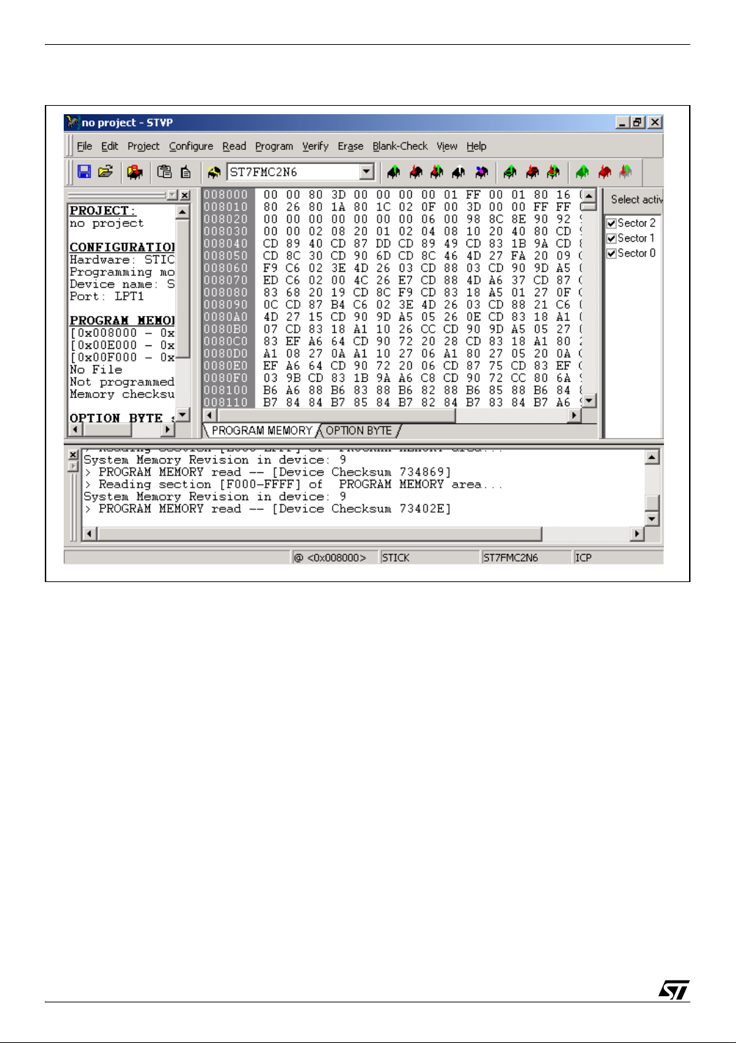
In order to program an MCU with the generated S19 file, you should also install the ST Visual
Programmer software (please visit our internet web-site) and use a programming interface
(STICK programmer for example for In-Circuit-Programming). The Visual Programmer tool
provides an easy way to erase, program and verify the MCU content.
Please note that the INDART STX kit from SOFTEC (see next chapter) is also a programming
tool (installation of DataBlaze Programmer is required).
7/77
Page 8
ST7MC THREE-PHASE BLDC MOTOR CONTROL SOFTWARE LIBRARY
Figure 1. STVisual Programmer software
1.2.2 Emulators
Two types of real-time development tools are available for debugging applications using
ST7MC:
- In-circuit debugger from Softec (salestype : STXF-INDART/USB)
The INDART from SOFTEC features an emulation and a programming tool. This is achieved
using the In-circuit debug module embedded on the MCU. The real-time features of the Indart
include access to real-time registers and 2 break-point settings. However, trace is not available.
- ST7MDT50-EMU3 emulator
Fully-featured emulator: real-time with trace capability, performance analysis, advanced
breakpoints, light logical analyser capabilities, etc. It can also function as a programming tool
when used with the delivered ICC ADDON module (select STMC-ICC as hardware target in
STVP7). This ICC-ADDON module allows In-Circuit-Debugging with STVD7.
8/77
Page 9

ST7MC THREE-PHASE BLDC MOTOR CONTROL SOFTWARE LIBRARY
1.3 LIBRARY SOURCE CODE
1.3.1 Download
The complete source files are available for free on the ST website (http://www.st.com/mcu), in
the Downloads section, as a zip file. This library is also copied by default on the hard-disk
when installing the ST7MC Control Panel from Softec micro systems, or available in the
Downloads section of www.softecmicro.com, software part (AK-ST7FMC System Software).
Important Note: It is highly recommended to check for the latest releases of the library
before starting any new development, and then verify from time to time
all release notes to be aware of any new features that might be of
interest for the project. Registration mechanisms are also available on
the web sites of ST and Softec Microsystems to automatically obtain
update information.
1.3.2 File structure
Once the files are unzipped, the following library structure appears, depending on the toolchain.
■ Library release 1.0
This library contains the workspace for both the STVD7 2.5.4 and STVD7 3.x IDEs. Four separate folders are provided (see Figure 2).
9/77
Page 10

ST7MC THREE-PHASE BLDC MOTOR CONTROL SOFTWARE LIBRARY
Figure 2. Library structure for release 1.0
BLDCmotor_1.0 \ BLDC sensor \ config
\ object
\ source
\ debug
\ release
\ BLDC sensorless
\ config
\ object
\ source
\ debug
\ release
\ Pair poles chk
\ config
\ object
\ source
\ debug
\ release
\ cosmic
\ metrowerks
\ cosmic
\ metrowerks
\ cosmic
\ metrowerks
\ cosmic
\ metrowerks
\ cosmic
\ metrowerks
\ cosmic
\ metrowerks
\ sci
1.4 UTILITIES
1.4.1 lib.h file
The purpose of this header file is to provide useful macros and type re-definitions which will be
used throughout the entire library:
– Re-definition of data types using the following convention: a first letter indicating if a variable
is signed (s) or unsigned (u), plus a number indicating the number of available bits (for instance: u8, s16, etc.),
– Defines for assembly mnemonics used in C source code: Nop(), Trap(), etc.
– Common macros used for bit-level access (SetBit, ClrBit, etc.), to get the dimension of an
array (DIM[x]), etc.
10/77
Page 11
ST7MC THREE-PHASE BLDC MOTOR CONTROL SOFTWARE LIBRARY
2 CUSTOMIZING THE WORKSPACE FOR YOUR ST7MC DERIVATIVE
2.1 USING STVD7 RELEASE 2.5.X
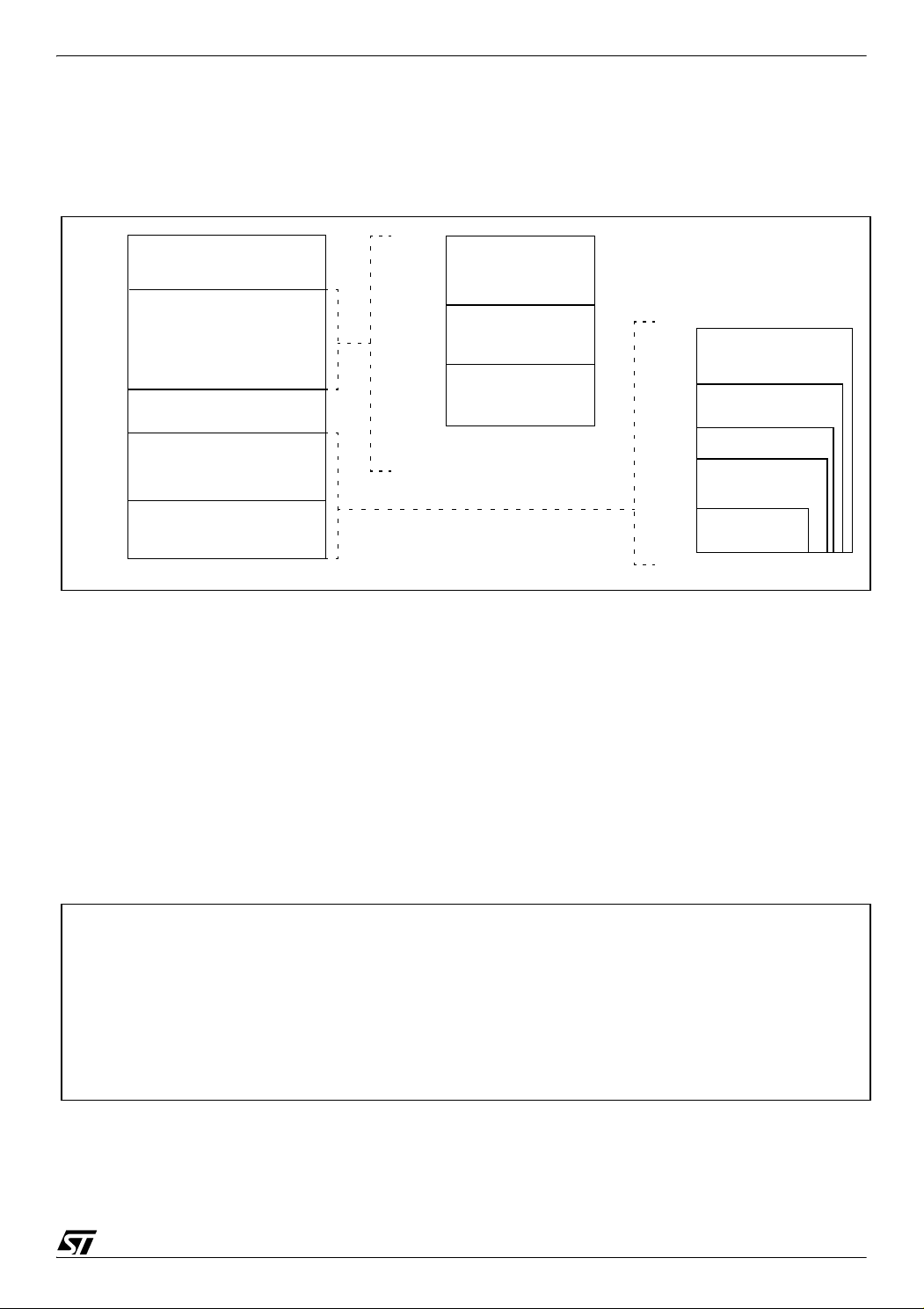
Figure 3. Memory Map
0000h
007Fh
0080h
067Fh
0680h
0FFFh
1000h
FFDFh
FFE0h
FFFFh
HW Registers
RAM
(1536/1024
768/384 Bytes)
Reserved
Program Memory
(60K, 48K, 32K, 24K, 8K)
Interrupt & Reset Vectors
0080h
00FFh
0100h
01FFh
0200h
01FFh
or 037Fh
or 047Fh
or 067Fh
Short Addressing
RAM (zero page)
256 Bytes Stack
16-bit Addressing
RAM
1000h
4000h
8000h
A000h
E000h
FFFFh
60 KBytes
48 KBytes
32 KBytes
24 KBytes
8 KBytes
The ST7MC memory is shown on Figure 3. The memory arrangement may vary depending on
the type of the MCU. Please refer to the datasheet in order to get more information.
The library is dedicated by default to the ST7FMC2N6B6 MCU (SDIP56, 32KB Flash, 1K
RAM). In order to target another ST7MC MCU, you may need to modify the C-toolchain configuration files. Here’s a basic example of what has to be done prior to any other modifications.
This example is based onto the ST7FMC2S4 MCU (TQFP 44, 16K Flash, 768 Bytes RAM)
2.1.1 Memory mapping with the COSMIC toolchain
Go into the ..\BLDC sensorless\config\Cosmic\ folder ( ..\BLDC sensor\config\Cosmic\ for
sensor driving mode).
Edit the "BLDC_Cosmic.lkf" file and check the following lines, in ‘SEGMENT DEFINITION’:
# SEGMENT DEFINITION (.text, .const, .data, .bss, .bsct, .ubsct, .eeprom are c compiler
predefined sections)
+seg .text -b0x8000 -m0x7f00 -nCODE -sROM # executable code
+seg .const -aCODE -it -sROM # constants and strings
+seg .bsct -b0x0080 -m0x007F -nZPAGE -sRAM # initialized variables in SHORT range
+seg .ubsct -aZPAGE -nUZPAGE -sRAM # uninitialized variables in SHORT range
+seg .share -aUZPAGE -is -sRAM #
+seg .bss -b0x0200 -m0x0280 -nUDATA -sRAM # uninitialized variables
+seg .data -aUDATA -nIDATA -sRAM # initialized variables
This section contains the memory placement for the object files, listed just after this declaration.
In order to target the memory size of the ST7MC2S4, the sizes of ROM and RAM memory have to be
changed (32K -> 16K Flash, 1K RAM -> 768 Bytes RAM)
shared segment
11/77
Page 12

ST7MC THREE-PHASE BLDC MOTOR CONTROL SOFTWARE LIBRARY
+seg .text -b0xc000 -m0x3f00 -nCODE -sROM # executable code
where 0xc000 is the new starting address of the program memory and 0x3fe0 the size in
bytes.
+seg .bss -b0x0200 -m0x0180 -nUDATA -sRAM # uninitialized variables
where 0x0180 is the new 16-bit addressing RAM memory in bytes.
2.1.2 Memory mapping with the METROWERKS toolchain
Go into ..\BLDC sensorless\config\Metrowerks ( ..\BLDC sensor\config\Metrowerks\ for sensor driving
mode).
Edit the "BLDC_Metrowerks.prm" file
SECTIONS
ZRAM = READ_WRITE 0x0080 TO 0x00FF; // zeropage
RAM = READ_WRITE 0x0200 TO 0x047F; // 16 bit adressing RAM
ROM_SEC_2 = READ_ONLY 0x8000 TO 0xDFFF; // sector 2
ROM_SEC_1 = READ_ONLY 0xE000 TO 0xEFFF; // sector 1
ROM_SEC_0 = READ_ONLY 0xF000 TO 0xFEFF; // sector 0 - 0xFF00 to 0xFFDF reserved for
ICC
This Section contains the memory locations of pages declared at the end of this file.
To target the memory size of the ST7MC2S4, ROM and RAM memory settings have to be changed (32K
-> 16K Flash, 1K RAM -> 768 Bytes RAM).
ROM_SEC_2 = READ_ONLY 0xC000 TO 0xDFFF; // sector 2
where 0xc000 is the new starting address of the program memory
RAM = READ_WRITE 0x0200 TO 0x027F; // 16-bit addressing RAM
where 0x027F is the ending address of the 16-bit addressing RAM memory
Important Note: The application layer has been written for the STMFC2NB6. Using a
different ST7MC sales type can imply the need for some modifications
to the library, according to the available features (some of the I/O ports
are not present on low-pin count packages). Please refer to the data
sheet for details.
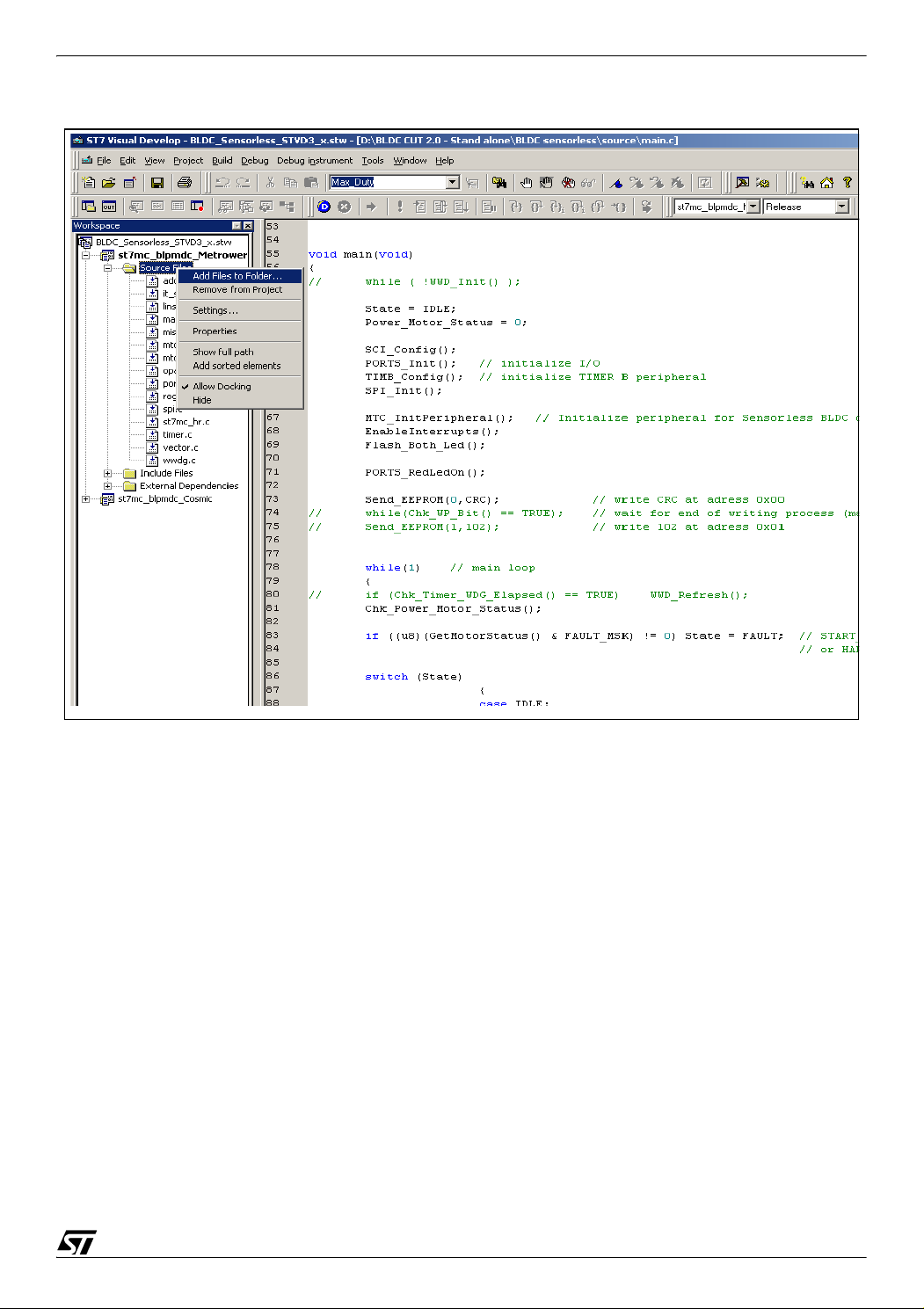
2.2 USING STVD7 RELEASE 3.X.X
The procedure is far easier with STVD7 3.x.x, as the makefile and linking command files are
automatically generated.
In the workspace window, just right click on the selected project (either cosmic or metrowerks)
and select “Add Files to Project”. You’ll be asked to select the source file.
12/77
Page 13
ST7MC THREE-PHASE BLDC MOTOR CONTROL SOFTWARE LIBRARY
When rebuilding the library, the configuration files will be updated accordingly.
13/77
Page 14

ST7MC THREE-PHASE BLDC MOTOR CONTROL SOFTWARE LIBRARY
2.3 "VERSION.H" FILE
The purpose of this file is to declare the compiler options which will be used throughout the entire library compilation process.
– Define the PMDC driving mode: voltage/current, open/closed loop
– In sensorless mode, 3 more options are added for the demagnetization type: hardware, hard-
ware with software backup, software.
Special care has to be taken for the demagnetization type, since the value range is 1, 2 and 3,
corresponding respectively to hardware, hardware with software backup, software demagnetization type (HW, HSW, SW).
Other compiler options can be disabled/enabled by writing 0 or 1 in front of each declaration (0
for disable, 1 for enable). Figure 4 gives an example when setting the current/closed loop/alternate hard soft demagnetization in sensorless mode.
Figure 4. Settings for current/closed loop/alternate hard soft demagnetization
(sensorless)
.....
/* Demagnetization type parameters */
#define HW 1 // 1 -> Hard demag only
#define HSW 2 // 2 -> Hard with soft backup
#define SW 3 // 3 -> Soft Demag only
/* Driving mode parameters */
#define CURRENT_MODE 0 // 0 -> Current mode
#define VOLTAGE_MODE 1 // 1 -> Voltage mode
/* Regulation type parameters */
#define OPEN_LOOP 0 // 0 -> Open loop
#define CLOSED_LOOP 1 // 1 -> Closed loop
....
/******************************************************************************/
/* Option settings used throughout the compilation process */
#define SENSOR_TYPE 0 // no use in sensorless
#define DEMAG_TYPE 2// no use in sensor mode
#define DRIVING_MODE 1
#define FEEDBACK_TYPE 1
mode
After choosing the desired compiler options, the whole library has to be rebuilt. To launch the
compilation, click on the ’rebuild all’ icon.
14/77
Page 15

ST7MC THREE-PHASE BLDC MOTOR CONTROL SOFTWARE LIBRARY
2.4 ADDITIONAL OR UP-TO-DATE TECHNICAL LITERATURE
More information can be found on the ST website (http://www.st.com/mcu).
More specifically, the latest documents and software can be found directly at:
http://www.st.com/mcu in the Downloads section
In addition, FAQ and Forums can be found directly at :
http://www.st.com/stonline/products/support/micro/st7/st7mc.htm
15/77
Page 16

ST7MC THREE-PHASE BLDC MOTOR CONTROL SOFTWARE LIBRARY
3 GETTING STARTED WITH THE LIBRARY USING THE ST7MC-KIT/BLDC
3.1 INTRODUCTION
There are two ways to get started with this software library.
The first way is to edit (with your motor specific features), compile and assemble the modules
described in Section 5 and Section 6 of this application note. Then, program ST7MC and run
your motor on hardware like the one provided in the ST7MC-KIT/BLDC Starter-kit.
The second way is to use the ST7MC-KIT/BLDC Starter-kit and follow this process:
- run and fine-tune the motor parameters with the GUI
- generate the *.H files and manually select/save the key parameters
- edit mtc.h file with key parameters
- compile, link, program ST7MC
- run the motor
If you are new to the BLDC environment or to the ST7MC product, the second method is
highly recommended and is described below.
3.2 RUNNING THE MOTOR
As a starting point, the open loop mode shall be used for the first trials. Low-duty cycle values
should be used also (alignment, ramp and real time settings) and then increased smoothly
step by step.
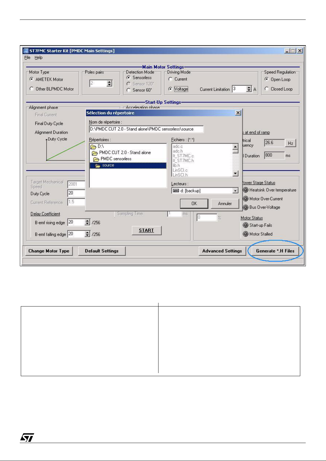
Once the motor settings have been finely adjusted (whatever the driving mode, sensor/sensorless), the parameters have to be ‘injected’ into the stand-alone library. Simply click on
‘Generate *.h Files’ and select the source directory of the stand-alone library.
16/77
Page 17
ST7MC THREE-PHASE BLDC MOTOR CONTROL SOFTWARE LIBRARY
The GUI will generate 1 dedicated header file containing the settings of the motor (mainly the
MTC peripheral settings) and another one containing the compiler options (see Figure 5).
Figure 5. Files generated in sensorless and sensor mode
SENSORLESS MODE
“MTC_Settings_Sensorless.h”
“Version.h”
Once previous files have been generated, launch a new compilation. Firmware will then be
compiled according to the new settings/compiler options automatically.
SENSOR MODE
“MTC_Settings_Sensor.h”
“Version.h”
17/77
Page 18

ST7MC THREE-PHASE BLDC MOTOR CONTROL SOFTWARE LIBRARY
3.3 STANDALONE MODE AND CLOSED LOOP OPERATION
To run a BLDC motor in standalone closed loop, the approach should be, for a given target
mechanical speed, to fine tune all the realtime parameters most adequate for this speed. For
each target speed, these values should be recorded in the form of a table, which will be used
by the ST7MC standalone firmware. You should collect data for 4 speeds: the min and max
speeds specified in the GUI advanced screen, and 2 intermediate speeds of your choice. The
ST7MC standalone firmware will then make a linear extrapolation of realtime parameters in
between the 4 specified speeds to ensure smooth operation.
Once the data is collected, edit the ‘mtc.h’ file and fill in the field dedicated to the Rising/Falling
Bemf, Ki, Kp coefficient calculation (see Figure 6).
Figure 6. ‘mtc.h’ field for coefficient computation
// See 'Mtc_Settings_Sensorless.h' for Freq_Min & Freq_Max values
//Fmin
#define Rising_Fmin 20 // Frequency min coefficient settings
#define Falling_Fmin 30
#define Ki_Fmin 10
#define Kp_Fmin 30
//F_1
#define F_1 1000 // 100 Hz
#define Rising_F_1 50 // Intermediate frequency 1 coefficient settings
#define Falling_F_1 40
#define Ki_F_1 20
#define Kp_F_1 10
//F_2
#define F_2 2000 //
#define Rising_F_2 30 // Intermediate frequency 2 coefficient settings
#define Falling_F_2 10
#define Ki_F_2 50
#define Kp_F_2 40
//Fmax
#define Rising_Fmax 10 // Frequency max coefficient settings
#define Falling_Fmax 16
#define Ki_Fmax 13
#define Kp_Fmax 18
200 Hz
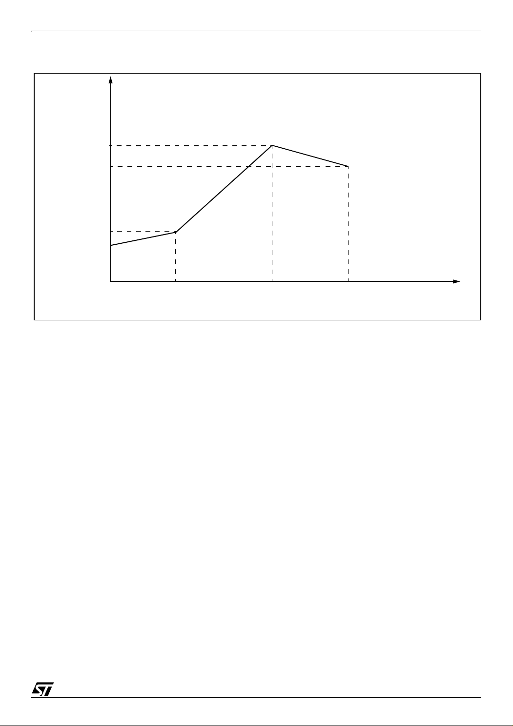
Once the motor runs, rising/falling Back-EMF and proportional/integer coefficients are computed following a linear curve between F_min and F_1, F_1 and F_2, F_2 and F_max (see
Figure 7). Note that F_min, F_1, F_2, F_max are electrical frequencies, with 0.1 Hz resolution
(for example F_1 = 1234 means F_1 = 123.4Hz).
18/77
Page 19
ST7MC THREE-PHASE BLDC MOTOR CONTROL SOFTWARE LIBRARY
Figure 7. Linear curve for coefficient computation
Rising/Falling Bemf
Ki, Kp
Rising_F_2, Falling_F_2
Ki_F_2, Kp_F_2
Rising_Fmax, Falling_Fmax
Ki_Fmax, Kp_Fmax
Rising_F_1, Falling_F_1
Ki_F_1, Kp_F_1
Rising_Fmin, Falling_Fmin
Ki_Fmin, Kp_Fmin
F_min
F_1
F_2
F_max
Target rotor
electrical
frequency
3.4 NOTE ON DEBUGGING TOOLS
3.4.1 Low voltage applications (below 30V)
For these voltage levels, the real-time emulator can be connected to the application, taking
care to connect the protective boards provided with the MDT50 emulator (refer to the emulator
datasheet for details). It offers trace and advanced breakpoint capabilities, as well as the possibility to automatically disable the PWM outputs on a breakpoint to avoid any DC current injection in the motor (see Figure 8).
This emulator is delivered with a set of three boards to protect some of the motor control dedicated I/Os from voltages greater than 5V. It is highly recommended to have them connected
during the development. A neutral board is also provided in case the protection networks impedance (1K series resistor plus 5V3 zener diode) is an issue for the application. Refer to the
ST7MDT50-EMU3 Probe user guide Section 3.1 for details.
An In-Circuit Debugging tool can also be directly connected, as long as an ICC connector is
available on the application.
Important Note: When using ICD, during a breakpoint, the clock circuitry is not disabled:
a permanent DC current may flow in the motor as the PWM outputs are
enabled. It is thus recommended to use a power supply with fast
current limitation capabilities or if possible to disable the PWM outputs
(by inserting MTC_DisableMCOutputs function) before the breakpoint.
19/77
Page 20
ST7MC THREE-PHASE BLDC MOTOR CONTROL SOFTWARE LIBRARY
Figure 8. Configuring the Motor Controller clock state on breakpoint with MDT50
3.4.2 Medium-high voltage application (above 30V)
Here the real-time emulator use is not recommended, even if protective boards are inserted.
Important Note: In the event of high voltage applications connected to the mains, the
application ground may be at a dangerous voltage; so too then would
be the MDT50 emulator (the protective boards do not provide
galvanic isolation).
For voltages above 30V, it is highly recommended to use only programmed devices. ICD debugging can be used in conjunction with an ICC isolation board, as the one provided with the
ST7MC-KIT/BLDC starter kit, but the limitations mentioned in Section 3.4.1 nevertheless
apply, and are even emphasized by the high voltage levels.
Good practice for real-time application debugging is to use “diagnostic tools” such as:
– RS232 communication which can be easily isolated,
– Standalone DAC (serial SPI-based model for instance) to be able to monitor signals on an
oscilloscope,
– Debug outputs of the ST7MC itself (MCDEM and MCZEM pins), to monitor the D, Z and C
events (refer to datasheet for details).
Refer to the application note AN438 (Safety Precautions for Development Tool Triac + Microcontroller) for further details when working with the mains supply.
20/77
Page 21

ST7MC THREE-PHASE BLDC MOTOR CONTROL SOFTWARE LIBRARY
3.5 USING YOUR OWN POWER STAGE
In order to configure the standalone library to match any kind of power stage, care should be
taken to observe the logic input diagrams of the drivers. The starter kit uses three L6386 highvoltage high and low side drivers; other devices may require adjustments, depending on
whether their logical inputs are active low or high. The ‘MPOL’ register has then to be set manually in the firmware. Modifications can be done in the ‘MTC_InitPeripheral’ routine (see
Figure 9). It has to be noted also that the option byte has to be updated accordingly (MCO
output states during reset).
Figure 9. MPOL register configuration
void MTC_InitPeripheral(void)
{
MTC_ResetPeripheral();
// Initialize registers in page 1 first
SET_MTC_PAGE(1);
MCONF = mem_MCONF;
MPWME = (u8)(mem_MPWME | DG_MSK); //Force output of debug signal
MPOL = ALL_ACTIVE_HIGH; // (L6386D) <-- to be updated according to your own
device characteristics
// ZVD bit=0; Z and D have opposite edge
The starter kit can also be connected directly to an external power stage using the socket J6
(26 pins).
3.6 CHECKING THE CURRENT SENSOR RESISTOR VALUE
The starter kit comes with a current sensor resistor of 0.047 Ohm (R21 on the schematic, see
Figure 10). The current limiter of the MTC cell relies on a comparator that turns off the PWM
when the voltage on this resistor has reached a limit (see Section 7.2.1 Voltage versus current
mode for more details). This voltage is amplified by a factor of 11 by the internal OPAMP con-
figured as a non-inverter amplifier (see R66 and R67 values).
21/77
Page 22

ST7MC THREE-PHASE BLDC MOTOR CONTROL SOFTWARE LIBRARY
Figure 10. Starter kit: zoom on the power stage
‘R21’ 47 milli-ohm
resistor acting as
a current sensor
3.6.1 Maximum current
The saturation voltage of the internal comparator is 5 Volts. Figure 11 summarizes the hardware configurations when the winding current is set to maximum.
22/77
Page 23

ST7MC THREE-PHASE BLDC MOTOR CONTROL SOFTWARE LIBRARY
Figure 11. Configuration at max. current
MCCREF
5 Volts
OAZ/MCCFI1
clock
PWM freq.
comparator
HV
Set
-
R
+
T1
A
Uout
OPAMP
X11
Usense
T4
47 milli-Ohm
Therefore, the maximum current can be calculated:
Imax = Vsaturation / (OPAMPgain x Rsense)
Previous formula applied to the starter kit leads to:
Imax = 5 / (11 x 0.047) = 9.67 amperes
The current sense resistor value has to be adjusted when a different working range is needed.
It is then necessary to decrease it when the current requirement is higher, or to increase it
when the current requirement is lower. It is also possible to adjust the OPAMP gain, but it has
to be remembered that:
– A High-gain OPAMP configuration may decrease EMC performance.
– A low-gain OPAMP combined with a high current sense resistor value will induce higher pow-
er loss (into the resistor).
– The power stage of the starter kit has been designed to handle power up to 1KW. For higher
power, a bigger heat sink and current capability IGBTs or MOSFETs may be required.
3.6.2 Interpreting the current feedback/settings in the GUI
Settings related to current values on the GUI are treated as if the current sensor value were a
47 milli-Ohm type (with OPAMP gain equal to 11). When using a different resistor value, settings concerning current can’t be read/written directly but have to be calculated manually
using a proportional coefficient equal to:
K = 47 milli-Ohm / new value
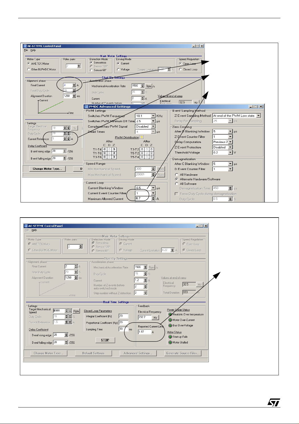
The actual current information is the one shown on the GUI multiplied by the proportional coefficient ‘K’ (See Figure 12 & Figure 13).
23/77
Page 24
ST7MC THREE-PHASE BLDC MOTOR CONTROL SOFTWARE LIBRARY
Figure 12. Using a 20 milli-Ohm resistor, K = 2.35 (47/20)
Actual value:
3x2.35 = 7.05 A
1x2.35 = 2.35 A
8.7x2.35 = 20.45 A
Figure 13. Using a 100 milli-Ohm resistor, K = 0.47 (47/100)
Actual value:
1.97x0.47 = 0.93 A
24/77
Page 25

ST7MC THREE-PHASE BLDC MOTOR CONTROL SOFTWARE LIBRARY
4 MODULES PRESENTATION, LIBRARY ROUTINES
4.1 LIBRARY REFERENCES
Functions are described in the format given below:
Synopsis This section lists the referenced include files and prototype declarations.
Description The functions are specifically described with a brief explanation of how
they are executed.
Input This section gives the format and units.
Returns Gives the value returned by the function, including when an input value
is out of range or an error code is returned.
Caution Indicates the limits of the function or specific requirements that must be
taken into account before implementation.
Warning Indicates important points that must be taken into account to prevent
hardware failures.
Functions called Used to prevent conflicts due to the simultaneous use of resources.
Code example Indicates the proper way to use the function if there are certain prereq-
uisites (interrupt enabled, etc.).
Some of these sections may not be included if not applicable (no parameters, obvious use,
etc.).
4.2 MTC SOFTWARE LAYER
The software related to the MTC peripheral is part of a module which is call ‘mtc.c’. This
module refers to all the routines needed to initiate and run the peripheral properly. The dedicated MTC hardware registers declaration are also grouped into a module named ‘mtc_hr.c’.
This module provides:
- Basic setup
- Control routines
- Related interrupt handling routines
- Speed acquisition for closed loop operation
Routine prototypes can be found in the ‘mtc.h’ header file.
25/77
Page 26

ST7MC THREE-PHASE BLDC MOTOR CONTROL SOFTWARE LIBRARY
4.2.1 List of available routines
The following is a list of available functions as listed in the mtc.h header file.
MTC_InitPeripheral . . . . . . . . . . . . . . . . . . . . . . . . . . . . . . . . . . . . . . . . . . . . . .page 27
MTC_StartMotor . . . . . . . . . . . . . . . . . . . . . . . . . . . . . . . . . . . . . . . . . . . . . . . .page 28
MTC_StopMotor . . . . . . . . . . . . . . . . . . . . . . . . . . . . . . . . . . . . . . . . . . . . . . . .page 29
Set_Duty . . . . . . . . . . . . . . . . . . . . . . . . . . . . . . . . . . . . . . . . . . . . . . . . . . . . . . page 30
Set_Target_Electrical_Frequency . . . . . . . . . . . . . . . . . . . . . . . . . . . . . . . . . . .page 31
active_brake . . . . . . . . . . . . . . . . . . . . . . . . . . . . . . . . . . . . . . . . . . . . . . . . . . . page 32
Get_Motor_Status . . . . . . . . . . . . . . . . . . . . . . . . . . . . . . . . . . . . . . . . . . . . . . .page 33
Set_Motor_Status . . . . . . . . . . . . . . . . . . . . . . . . . . . . . . . . . . . . . . . . . . . . . . . page 34
Chk_Motor_Stalled . . . . . . . . . . . . . . . . . . . . . . . . . . . . . . . . . . . . . . . . . . . . . . page 35
MTC interrupt handling routines are described in the next chapter.
26/77
Page 27

ST7MC THREE-PHASE BLDC MOTOR CONTROL SOFTWARE LIBRARY
MTC_InitPeripheral
Synopsis #include "mtc.h"
void MTC_InitPeripheral(void)
Description The purpose of this function is to (re-)initialize the MTC cell. A reset of
this peripheral is done first, and the hardware registers are then set with
appropriate values.
Caution It must be noted that part of MPOL and MDTG registers are written
once, meaning they cannot be modified any further once the
MTC_InitPeripheral() function has been executed
Functions called MTC_ResetPeripheral()
See also ST7MC Datasheet: MTC chapter.
27/77
Page 28

ST7MC THREE-PHASE BLDC MOTOR CONTROL SOFTWARE LIBRARY
MTC_StartMotor
Synopsis #include "mtc.h"
void MTC_StartMotor(void)
Description This function Initializes HW registers and SW variables needed in real
time for the motor drive. To ensure a proper start-up, the bootstrap capacitors of the high side switch drivers are refreshed. Finally, this function performs the alignment of the rotor in a known position, and sets the
flags of expected MTC interrupt events.
Functions called Init_PI (closed loop only), MTC_EnableDirectAccess,
MTC_DisableDirectAccess, MTC_EnableOutputs, RefreshBootstrap,
MTC_EnableClock, MTC_DisableClock, AlignRotor
See also ST7MC Datasheet: MTC chapter.
28/77
Page 29

ST7MC THREE-PHASE BLDC MOTOR CONTROL SOFTWARE LIBRARY
MTC_StopMotor
Synopsis #include "mtc.h"
void MTC_StopMotor(void)
Description This function disables all motor control related interrupts and switches
off all transistors. This puts the windings in floating state once they are
completely demagnetized.
Functions called MTC_EnableDirectAccess, MTC_DisableDirectAccess
29/77
Page 30

ST7MC THREE-PHASE BLDC MOTOR CONTROL SOFTWARE LIBRARY
Set_Duty
Synopsis #include "mtc.h"
void Set_Duty(u16 duty)
Description This function is used to refresh the MCPUH/L register contents
(MCPVH/L in current mode).
Input The ‘duty’ is a u16 variable, and has to be set according to the PWM fre-
quency (MCPOH/L registers) for both voltage or current mode.
The desired duty cycle is set using this formula:
Duty = desired duty (0 to 100%) x MCPOH/L (voltage mode’)
Duty = desired current limitation (Amp) x MCPOH/L / 9.7(current mode)
Caution In voltage mode, the ‘duty’ variable is directly linked to the PWM duty
cycle while in current mode, the ‘duty’ variable sets the voltage reference (MCPVH/L, actually the current limitation) at the input of the MTC
cell comparator (MCCREF pin, via a RC filter on the board).
See also ST7MC Datasheet: MTC chapter.
Code example Voltage mode:
20 Khz PWM frequency (ratio between 12-bit PWM clock and PWM frequency, MCPOHL = 16 MHz/20kHz = 800), desired duty = 40%:
duty = 40 x MCPOHL/100 = 320
-> Update_Duty(320);
Current mode:
*Fixed 10 Khz PWM frequency (MCPOHL = 1600), desired current limitation = 4 Amp:
duty = 4 x MCPOHL/9.7 = 4 x 1600/9.7 =
-> Update_Duty(660);
* hardware dependant. For other PWM frequencies, please check the
RC filter value at the input of the MTC comparator cell (MCCREF pin).
30/77
Page 31

ST7MC THREE-PHASE BLDC MOTOR CONTROL SOFTWARE LIBRARY
Set_Target_Electrical_Frequency
Synopsis #include "mtc.h"
void Set_Target_Electrical_Frequency(u16 target_freq)
Description This function is used to refresh the MCPUH/L register contents
(MCPVH/L in current mode). The output of the PI regulation loop routine
is used to do so.
Input The ‘target_freq’ is a u16 variable, and has to be set according to the de-
sired target frequency (0.1Hz resolution).
The target electrical frequency is given by:
target_freq = desired electrical frequency x 10 (0.1 Hz resolution)
Caution Frequency is given with 0.1Hz resolution.
Functions called regul_PI
See also ST7MC Datasheet: MTC chapter.
Code example desired electrical frequency : 100 Hz:
target_freq = 100 Hz x 10 = 1000;
-> Set_Target_Electrical_Frequency(1000)
Reminder:
Electrical frequency = number of pair poles x mechanical frequency
RPM speed = 60 x Mechanical frequency (RPM: revolutions per minute)
example: electrical frequency = 100 Hz, motor with 8 pair poles:
100Hz electrical <-> 100/8 =12.5Hz mechanical <-> 12.5 x 60=750 RPM
31/77
Page 32

ST7MC THREE-PHASE BLDC MOTOR CONTROL SOFTWARE LIBRARY
active_brake
Synopsis #include "mtc.h"
BOOL active_brake(u16 duty, u16 time)
Description The purpose of this function is to switch the active brake of the motor, by
sinking a DC current in 1 phase, another one being grounded.
Input Duty cycle applied during active brake phase, with the Time given in
milli-seconds
Returns TRUE if brake time elapsed or duty sets to 0.
Caution In voltage mode, the ‘Duty’ variable is directly linked to the PWM duty
cycle while in current mode, the ‘Duty’ variable sets the voltage reference at the input of the MTC cell comparator (MCCREF pin, via a RC
filter on the board).
Functions called MTC_EnableDirectAccess, MTC_DisableDirectAccess
See also ST7MC Datasheet: MTC chapter.
Code example The ‘duty’ is a u16 variable, and has to be set according to the PWM fre-
quency (MCPOH/L registers).
Example:
PWM frequency set at 10 Khz, MCPOH/L = 1600 (ratio between 12-bit
PWM clock and PWM frequency 16 MHz/10kHz = 1600)
Desired duty = 40% = 40 x MCPOHL/100 = 40 x 1600/100 = 640
Desired braking time : 2 sec = 2000 ms
-> if (active_brake(640,2000) == TRUE) State = STOP; // stop motor
32/77
Page 33

ST7MC THREE-PHASE BLDC MOTOR CONTROL SOFTWARE LIBRARY
GetMotorStatus
Synopsis #include "mtc.h"
u8 GetMotorStatus(void)
Description This function returns the ‘MotorStatus’ byte.
Bit description:
MotorStatus
Sensorless
EMERGENCY_STOP
START_UP_FAILED
HARD_FAILURE
MOTOR_STALLED
LAST_FORCED_SWITCH
FIRST_AUTO_SWITCH
AUTO_SWITCH
MotorStatus
Sensor
EMERGENCY_STOP
HARD_FAILURE
6
5
7
6
7
4
54
3
3
21
2
0
0
1
MOTOR_STALLED
Returns unsigned char
33/77
Page 34

ST7MC THREE-PHASE BLDC MOTOR CONTROL SOFTWARE LIBRARY
SetMotorStatus
Synopsis #include "mtc.h"
void SetMotorStatus(u8 status)
Description This function updates the ‘MotorStatus’ byte according to the ‘status’
byte parameter. Please see ‘GetMotorStatus’ routine description for
status byte definition.
Input unsigned char
34/77
Page 35

ST7MC THREE-PHASE BLDC MOTOR CONTROL SOFTWARE LIBRARY
Chk_Motor_Stalled
Synopsis #include "mtc.h"
void Chk_Motor_Stalled(void)
Description The purpose of this function is to check the ratio of the MTC cell set in
the MPCR register. If the ratio is equal to the maximum ratio (15), then
the bit ‘MotorStalled’ of ‘Power_Motor_Status’ is set.
See also ST7MC Datasheet: MTC chapter.
35/77
Page 36

ST7MC THREE-PHASE BLDC MOTOR CONTROL SOFTWARE LIBRARY
4.2.2 List of MTC interrupt routines
The following is a list of the MTC interrupt handling routines. These functions are all included
in the ‘mtc.c’ module.
MTC_U_CL_SO_IT. . . . . . . . . . . . . . . . . . . . . . . . . . . . . . . . . . . . . . . . . . . . . .page 37
MTC_C_D_IT . . . . . . . . . . . . . . . . . . . . . . . . . . . . . . . . . . . . . . . . . . . . . . . . . .page 38
MTC_R_Z_IT. . . . . . . . . . . . . . . . . . . . . . . . . . . . . . . . . . . . . . . . . . . . . . . . . . . page 42
36/77
Page 37

ST7MC THREE-PHASE BLDC MOTOR CONTROL SOFTWARE LIBRARY
MTC_U_CL_SO_IT
Synopsis #include "mtc.h"
void MTC_U_CL_SO_IT(void)
Description This interrupt routine is entered once there is a current limitation, PWM
update or Sampling Out event. Only the current limitation event is processed in the library: status flag is reset, and the bit ‘OverCurrent’ of
‘Power_Motor_Status’ is set.
See also ST7MC Datasheet: MTC chapter.
Figure 14. CLI event processing (sensorless/sensor)
CLI interrupt request
Set overcurrent flag in Power_Motor_Status
Disable CLI interrupt for 300 ms
Return from interrupt
37/77
Page 38

ST7MC THREE-PHASE BLDC MOTOR CONTROL SOFTWARE LIBRARY
MTC_C_D_IT
Synopsis #include "mtc.h"
void MTC_C_D_IT(void)
Description This function is dedicated to the Commutation and Demagnetization in-
terrupt service routine. Figures 15,16,17,18 & 19 show the routine flow-
charts.
See also ST7MC Datasheet: MTC chapter.
Figure 15. Commutation event processing (Sensor mode only)
C interrupt request?
Preload active phase on next C event: MPHST with phase,
MCRB with comparator edge, PWM orientation
Voltage mode
: save MCPUHL and force duty cycle during demag if enabled
MWGHT = RISING/FALLING delay
Return from interrupt
38/77
Page 39

ST7MC THREE-PHASE BLDC MOTOR CONTROL SOFTWARE LIBRARY
Figure 16. Commutation event processing (Sensorless mode only)
Reset RPICounter
Preload active phase on next C event: MPHST with phase,
MCRB with comparator edge, demagnetisation mode and PWM orientation
Voltage mode: save MCPUHL and force duty cycle during demag
StepIndex = StepIndex + 1
if enabled
C interrupt request?
SW DEMAG
Adjust soft demagtime according
to RPICounter
yes
Preset soft demag time + MCOMP > 0xff
MotorStatus?
no
HSW DEMAG
HW DEMAG
FORCED_SWITCH
C_IT_ForcedSW
LAST_FORCED_SWITCH FIRST_AUTO_SWITCH
MDREG = MCOMP/(SWITCHED_SW_DEMAG)
Wait for Z event (MCOMP=255)
MWGHT = TRANSITION_DELAY
Enable autoswitchand relevant interrupts
MotorStatus= FIRST_AUTO_SWITCH
Return from interrupt
MWGHT = AUTO_DELAY
Init PI buffer (Step_Z[ ])
Reset delay_counter
MotorStatus= AUTO_SWITCH
C_IT_AutoSW
AUTO_SWITCH
39/77
Page 40

ST7MC THREE-PHASE BLDC MOTOR CONTROL SOFTWARE LIBRARY
Figure 17. Commutation event processing (Sensorless mode only) continued
SW DEMAG
HW DEMAG
Update MCOMP& MPRSR with step
time and ratio stored in RAMP[ ]
Enable D event if RampIndex= 2
MDREG = MCOMP/(SWITCHED_SW_DEMAG)
Ramp finished
without success?
no
Bemf blanking over?
(RampIndex
Bemf are present and consecutive?
(same number of C & Z event?)
= bemf_blank?)
no
C_IT_ForcedSW
HSW DEMAG
yes
Stop motor
yes
Enable Z event
yes
CeventCounter++
no
Reset CeventCounter
& BemfCounter
Return from interrupt
40/77
Page 41

ST7MC THREE-PHASE BLDC MOTOR CONTROL SOFTWARE LIBRARY
Figure 18. Commutation event processing (Sensorless mode only) continued
HSW DEMAG SW DEMAG HW DEMAG
SDM bit set? (hard + soft demag ongoing?)
yes
yes
RM event?
no
no
MDREG = SoftDemagTime + MCOMP
delay_counter <= MAX_DELAY_COUNTER?
MWGHT = RISING/FALLING delay
SoftDemagTime
MCOMP+SoftDemagTime / 2^(RP_counter) > 0xff ?
Adjust SoftDemagTime& RPICounter
no
= SoftDemagTime*2
yes
for correct MTIM timer overflow
yes
delay_counter = AUTO_DELAY_STEP?
C_IT_AutoSW
no
Increase delay_counter
no
Update MDREG with user settings
MDREG = preset demag
Return from interrupt
C_IT_AutoSW C_IT_AutoSW
time
yes
MWGHT = MEDIUM_DELAY
Figure 19. Demagnetisation event processing (Sensorless mode only)
SENSORLESS
SoftDemagTime
Autoswitchmode?
= 1.25 x (MDREG-MCOMP)
Return from interrupt
Voltage mode?
yes
Restore MCPUHL values if duty
no
cycle has been forced during demag
HSW DEMAG SW DEMAG
noyes
SoftDemagTime = 1.25 x MDREG
D interrupt request?
HW DEMAG
41/77
Page 42

ST7MC THREE-PHASE BLDC MOTOR CONTROL SOFTWARE LIBRARY
MTC_R_Z_IT
Synopsis #include "mtc.h"
void MTC_R_Z_IT(void)
Description This function is dedicated to the Zero-Crossing and Ratio Increment/
Decrement interrupt service routines. Figures 20, 21, 22, 23, 24 & 25
show the routine flowcharts.
See also ST7MC Datasheet: MTC chapter.
Figure 20. Z event processing (sensorless mode only)
Z interrupt request?
yes no
Save MZREG value and
prescaler ratio into Step_Z buffer
(save step time between two
zero crossing events)
Autoswitchmode?
no
Return from interrupt
BemfCounter++
Correct number of
Successive Bemf detected?
MotorStatus = LAST_FORCED_SWITCH
yes
Center last zerocrossing in the middle
of 2 C events (
MCOMP = MZREG x 2
)
42/77
Page 43

ST7MC THREE-PHASE BLDC MOTOR CONTROL SOFTWARE LIBRARY
Figure 21. Z event processing (Sensor mode only)
Save MZREG value
and prescaler ratio into Step_Z buffer
(save step time between two
zero crossing events)
Z interrupt request?
Return from interrupt
Figure 22. RP event processing (Sensorless mode only)
HW DEMAG
yes no
RPICounter = 0?
RPICounter = RPICounter-1
RPICounter = 0?
no
Return from interrupt
RP interrupt request?
HSW DEMAG
SW DEMAG
yes
MDREG = SoftDemagTime
43/77
Page 44

ST7MC THREE-PHASE BLDC MOTOR CONTROL SOFTWARE LIBRARY
Figure 23. RP event processing (Sensor mode only)
RP interrupt request?
Return from interrupt
Figure 24. RM event processing (Sensorless mode only)
RM interrupt request?
Set RM_EVT Flag
Return from interrupt
Figure 25. RM event processing (Sensor mode only)
RM interrupt request?
44/77
Return from interrupt
Page 45

ST7MC THREE-PHASE BLDC MOTOR CONTROL SOFTWARE LIBRARY
4.3 APPLICATION LAYER
The application layer is split into modules; each module comes with a set of routines dedicated
to a peripheral, event (interrupt routines), or are grouped by functionality. The following information summarizes the most important routines in the different modules.
regul.c . . . . . . . . . . . . . . . . . . . . . . . . . . . . . . . . . . . . . . . . . . . . . . . . . . . . . . . . . . . . . page 45
adc.c . . . . . . . . . . . . . . . . . . . . . . . . . . . . . . . . . . . . . . . . . . . . . . . . . . . . . . . . . . . . . . page 45
it_ST7MC.c . . . . . . . . . . . . . . . . . . . . . . . . . . . . . . . . . . . . . . . . . . . . . . . . . . . . . . . . . page 46
ports.c . . . . . . . . . . . . . . . . . . . . . . . . . . . . . . . . . . . . . . . . . . . . . . . . . . . . . . . . . . . . . page 47
LinSCI.c. . . . . . . . . . . . . . . . . . . . . . . . . . . . . . . . . . . . . . . . . . . . . . . . . . . . . . . . . . . . page 48
4.3.1 regul.c
This module contains the code of the PI regulation loop, which is used for closed loop operation.
The ‘u16 Period_To_Frequency(void)’ routine converts the Step_Z buffer information into
frequency (the Step_Z buffer contains the time elapsed between 7 zero-crossing events ->
corresponds to the time of six (6) steps period of the electrical frequency).
The ‘u16 regul_PI(u16 Target_Freq)’ routine computes the PI output according to Ki, Kp,
sampling time, and target electrical frequency. The returned value is a 10-bit long integer (0 to
1024).
4.3.2 adc.c
This module starts and initializes the analog to digital converter, and launches upon request a
conversion on a channel. It is able to provide ready-to-use values to the upper software layer.
It was basically written to monitor signals that vary slowly, such as trimmers, since the returned results are averaged values of 8 successive conversions.
The ‘u16 ADC_Get_10bits(u8 Channel)’ and ‘u8 ADC_Get_8bits(u8 Channel)’ functions
return the ADC result on the selected channel.
The ‘u8 Get_RV1(void)’, ‘u8 Get_RV2(void)’ and ‘u8 Get_RV3(void)’ routines return the
value read on the potentiometers connected to the MCU (RV1, RV2, RV3).
The ‘BOOL Get_Temperature(void)’ returns a boolean. This function returns ‘TRUE’ if the
voltage on the thermal resistor connected to channel AIN0 has reached the threshold level or
if the voltage has not yet reached back the threshold level minus the hysteresis value after an
overheat detection.
In order to set the temperature and hysteresis threshold, the ‘NTC_THRESHOLD’ and
‘NTC_HYSTERIS’ values can be adjusted in the adc.c file.
45/77
Page 46

ST7MC THREE-PHASE BLDC MOTOR CONTROL SOFTWARE LIBRARY
The ‘BOOL Get_HVBus(void)’ returns a boolean. This function returns ‘TRUE’ if the voltage
of the HVBUS connected to channel AIN1 has reached the threshold level or if the voltage has
not yet returned to the threshold level minus the hysteresis value after an over-voltage detection.
In order to set the voltage and hysteresis threshold, the ‘HVBUS_THRESHOLD’ and
‘HVBUS_HYSTERIS’ values can be adjusted in the adc.c file.
4.3.3 it_ST7MC.c
This module contains all non-MTC related interrupt service routines. In the stand alone
firmware, the timer B resource is the only one to be used. The output compare capability is
used in order to decrease 2 different time bases, 10ms and 1ms (see ‘Timer.c’ file for the timer
B registers configuration).
Basically, unless equal to 0, variables are decreased by one each timer B output compare interrupt event (every 10ms or 1ms for output compare 1 and 2 respectively). Therefore, a variable ‘VAR’ is loaded with ‘50’ in the main code and decreased by one every 10 ms, and will
reach ‘0’ after 500ms (490 to 500 ms if the initialization of ‘VAR’ is done outside of the interrupt
routine).
Figure 26. Time base Principle: Timer B output compare 1 interrupt every 10ms
Main routine:
VAR = 50 VAR = 49 VAR = 48
int
10 ms
int
int
int
int
Clear Status flag, refresh timer B output compare registers,
and update variables used for timing purpose
VAR = 47
For more information regarding the configuration of this peripheral, please refer to the data
sheet of the MCU, ‘16-bit timer’ section.
46/77
Page 47

ST7MC THREE-PHASE BLDC MOTOR CONTROL SOFTWARE LIBRARY
4.3.4 ports.c
The purpose of the ports.c module is to centralize all information regarding the I/O ports (including the alternate functions) within the same file.
It is intended to clarify the sharing of I/Os between the peripherals and the functions requiring
standard input/outputs, such as LEDs and push button reading.
I/Os are initialized at the beginning of the main program, using the ‘void PORTS_Init(void)’
function. Two functions are handled by this module, needed when running the software library
with the ST7MC starter kit hardware.
4.3.4.1 Push button reading
The function ‘BOOL key_scan(void)’ returns a boolean, TRUE if the push button (connected
to PC0) has been pushed during a minimum duration. This duration can be programmed in
ms, to debounce the button reading. This timing is verified using ‘it_ST7MC.c’ module resources, in ‘void TIMB_Interrupt(void)’ interrupt routine.
The location of the push button (port and bit location) must be specified at the beginning of the
ports.c file. The push button must be connected between ground and a pull-up resistor to get
a low level on the input pin when it is pushed (refer to ST7MC starter kit schematics for details).
4.3.4.2 LEDs
A set of functions can be called to switch ON, OFF or toggle the two LEDs present on the
starter kit: PORTS_RedLedOn, PORTS_RedLedOff, PORTS_RedLedToggle, etc. It must
be remembered that these two LEDs are powered using a single I/O (see schematics for details). Consequently:
– they cannot be turned ON simultaneously
– the I/O port state can be configured either as an output or as a floating input to switch OFF
the LEDs.
4.3.5 spi.c
This module contains the code related to the SPI peripheral. The initialization of this peripheral
is made within the ‘void SPI_Init(void)’ function. Care should be taken when configuring the
SPI interface in accordance with the system (particularly operating frequency and polarity).
Communication with a serial EEPROM can be done using the ‘Send_EEPROM(u8 address,
u8 data)’ and ‘Read_EEPROM(u8 address)’ routines.
47/77
Page 48

ST7MC THREE-PHASE BLDC MOTOR CONTROL SOFTWARE LIBRARY
4.3.6 LinSCI.c
This module contains the code related to the LINSCI serial communication interface and gives
an example of configuration and usage (with the ‘void SCI_Config(void)’ and ‘void
SCI_Send_Data(u8 data)’ routines) and the ‘TTY_7.exe’ executable file. You can find the executable in the ‘SCI’ folder of the stand alone firmware. Working TTY Settings with the stand
alone firmware are as follow:
- Baud Rate 38.4K, Data Bits 8, Parity none, Stop Bits 1, RTS/CTS enable, other options disabled.
When running the code in:
- Closed loop : the MCU feeds back respectively the rising, falling Bemf delay coefficients, integral, proportional coefficients, motor frequency (LSB then MSB), then ‘0’ (decimal values).
- Open loop : the MCU feeds back respectively the rising, falling Bemf delay coefficients, the
motor frequency (LSB then MSB), then ‘0’, ‘0’, ‘0’ (decimal values).
Those settings can be changed in the ‘main.c’ file, by modifying the values entered in the
‘Lin_Tx_Buffer[0...7]’.
Figure 27. Running TTY_7.exe on a PC (open loop firmware)
48/77
Page 49

ST7MC THREE-PHASE BLDC MOTOR CONTROL SOFTWARE LIBRARY
5 HOW TO DEFINE AND ADD A MODULE (STVD7 2.5.X)
This chapter describes how to define and declare a new module within the library. The example is based on the addition of 2 files: ‘my_file.c’ and the corresponding header file
‘my_file.h’. Users of STVD7 3.x can refer to Section 2.3.
The first step is the creation of two new files. You can either copy and paste existing files and
rename them, or click on the ‘new files’ icon and save it in the right format (*.c or *.h extension).
The new files containing the user code will generate a new ‘my_file.o’ object file that has to be
declared in the toolchain configuration files.
5.1 COSMIC TOOLCHAIN
For COSMIC users, modifications have to be done in BLDC_Cosmic.lkf and
BLDC_Cosmic.mak files.
In BLDC_COSMIC.lkf, the new object file has to be added to the main object file list (see
Figure 28). However, if special options are required (for example, no optimization, or the
forced placement of variables in memory), then it has to be declared in another section (e.g.
after the main list) with the correct settings. See your C toolchain documentation for further details.
Figure 28. BLDC_COSMIC.lkf
# OBJECT FILES
..\..\object\cosmic\main.o
..\..\object\cosmic\LinSCI.o
.....
..\..\object\cosmic\my_file.o
In BLDC_Cosmic.mak, ‘my_file.c’ has to be added in the C source file list (see Figure 29) and
the list of dependencies has to be updated accordingly (see Figure 30).
Figure 29. BLDC_Cosmic.mak, C source list
C_SRC = main.c \
mtc.c \
vector.c \
opamp.c \
.....
my_file.c \
49/77
Page 50

ST7MC THREE-PHASE BLDC MOTOR CONTROL SOFTWARE LIBRARY
Figure 30. BLDC_Cosmic.mak, dependencies
# RULES FOR MAKING THE OBJECT FILES:
main.o: main.c version.h lib.h RAM_Sensorless.h
$(CC) ..\..\source\main.c
.....
my_file.o: my_file.c my_file.h
$(CC) ..\..\source\my_file.c
5.2 METROWERKS TOOLCHAIN
For METROWERKS users, modifications have to be done in BLDC_Metrowerks.prm and
BLDC_Metrowerks.mak files; in BLDC_Metrowerks.prm the new object file has to be added
in the ‘Project module list’ section (see Figure 31). In BLDC_Metrowerks.mak, the new source
file and the corresponding dependencies have to be set in the ‘Application Files’ section (see
Figure 32).
Figure 31. BLDC_Metrowerks.prm
/*** PROJECT MODULE LIST ***/
NAMES
main.o
ST7MC_hr.o+
mtc_hr.o+
....
my_file.o
ansi.lib
END
Figure 32. BLDC_Metrowerks.mak
# --------------------------- APPLICATION FILES ------------------------------main.o : $(ENV) main.c version.h lib.h RAM_Sensorless.h
$(CC) main.c
ST7MC_hr.o : $(ENV) ST7MC_hr.c ST7MC_hr.h mtc_hr.h version.h lib.h
$(CC) ST7MC_hr.c
.....
my_file.o : $(ENV) my_file.c my_file.h
$(CC) my_file.c
50/77
Page 51

ST7MC THREE-PHASE BLDC MOTOR CONTROL SOFTWARE LIBRARY
6 CODE EXAMPLE
This section gives a very simple code example. Once an action on the start button is detected,
the motor starts and runs in open loop voltage sensorless mode with a duty cycle of 25%; once
an action on the stop button is detected, an active brake procedure is engaged for 2 seconds
with a duty cycle of 17%, then the power stage is switched off.
Warning: This code example assumes that correct settings have been entered
for the alignment phase and ramp data. Modifications may be done
using the Graphical User Interface provided with the demokit (by
clicking on the ‘generate *.h files’ icon).
51/77
Page 52

ST7MC THREE-PHASE BLDC MOTOR CONTROL SOFTWARE LIBRARY
Figure 33. Code example
While(1) // main loop
// if (Chk_Timer_WDG_Elapsed() == TRUE)WWD_Refresh();
Chk_Power_Motor_Status();
{
if ((u8)(GetMotorStatus() & FAULT_MSK) != 0) State = FAULT; // START_UP_FAILED
switch (State)
// overvoltage, overtemperature
if (GetMotorStatus() & AUTO_SWITCH)
{
}
Chk_Motor_Stalled();
if (timer_10ms == 0) PORTS_GreenLedOn();
break;
{
case IDLE:
if (timer_10ms == 0) PORTS_RedLedOn(); // red LED back to normal after
if (key_scan() == TRUE) State = START;
break;
case START:
if (MTC_StartMotor() == TRUE) State = RUN;
break;
case RUN:
if (ValBit(Flag_MTC,SAMP_EVT)) // update PWM?
{
Falling_bemf = (u8)(Get_RV3()); // read RV3 & set falling
Rising_bemf = (u8)(Get_RV2()); // read RV2 & set rising Bemf
Set_Duty((u16)(PWM_FREQUENCY*25/100)); // 25% duty cycle
}
if (key_scan() == TRUE) State = BRAKE;
// or MOTOR_STALLED
// or HARD_FAILURE
// or EMERGENCY_STOP?
detection
// Bemf coefficient accordingly
// coefficient accordingly
if (active_brake((PWM_FREQUENCY*17/100),2000) == TRUE) State = STOP;
MTC_StopMotor();
PORTS_RedLedOn();
PORTS_RedLedOn();
}
52/77
case BRAKE:
// Brake_Duty = 17%
break;
case STOP:
State = IDLE;
break;
case FAULT:
default:
MTC_StopMotor();
if ((u8)(GetMotorStatus() & FAULT_MSK) == 0) State = IDLE;
break;
}
Page 53

ST7MC THREE-PHASE BLDC MOTOR CONTROL SOFTWARE LIBRARY
7 PMDC (PMAC) MOTOR CONSIDERATIONS
7.1 PHYSICAL CONSIDERATIONS
7.1.1 Checking the number of pair poles of the motor
In most cases, there is an easy way to check how many pair poles are present with the motor
you are working with. This applies only to motors from which you can observe any mechanical
effect (by looking at the axis for example).
The trapezoidal driving method is based on 6 steps, and each step involves a particular low /
high side driver configuration. 1 electrical cycle is then accomplished within 6 steps. The
number of pair poles gives the link between electrical frequency and mechanical frequency:
mechanical frequency (hertz) = electrical frequency (hertz) / number of pair poles
Thus, by switching from one step to another at a very low frequency (e.g. 1Hz) and simply by
controlling the mechanical effect by sight, we can determine the number of pole pairs by
counting the number of steps within 1 mechanical cycle. It is given by:
number of pole pairs = total number of steps / 6
Example: assuming that 24 steps are needed to describe 1 mechanical cycle (e.g. 360 degrees on the axis of the motor), then the number of pole pairs is 24/6 = 4.
The software package includes a workspace containing a firmware example in order to drive
the motor step by step at a frequency of 1Hz. You can open it in the ‘Pair poles chk’ folder
and open the dedicated workspace to your toolchain. This folder contains also a s19 file (in
‘S19 file for EEPROMER’) so that you can program a MCU directly and avoid the use of an
emulator. RV1 potentiometer is used to set the PWM duty cycle. The Start/Stop push button
launches/stops the procedure.
Warning: Operations are made in voltage mode with a PWM frequency of 10Khz
and duty cycle is set via RV1 potentiometer. Make sure that the duty
cycle is not too high as the winding currents can increase very quickly
in this particular mode of operation.
53/77
Page 54

ST7MC THREE-PHASE BLDC MOTOR CONTROL SOFTWARE LIBRARY
7.1.2 Connecting the sensor outputs to the board
Two configurations are commonly used: sensor 60 / sensor 120 degrees.
The easiest and most time-efficient solution is to connect the motor cables into the demokit by
trying all the connection style combinations.
First you need to check which sensor distribution is used by connecting the sensor outputs to
a scope and running the motor smoothly (by hand, for example). The consecutive events (in
the time domain) have to be monitored (with a scope/multimeter): 3 successive rising/falling
edges means a sensor 60 configuration, while an alternate rising/falling edge means a sensor
120 configuration.
Now that the sensor distribution is known, you have to randomly connect the sensor outputs to
the demokit (select the right sensor configuration in the GUI). As there are 3 phases (let’s say
P1,P2 and P3), that simply means we have 6 possibilities of connection: P1P2P3, P1P3P2,
P2P1P3, P2P3P1, P3P1P2 and P3P2P1.
For each connection, you may try to start the motor (with the GUI for example) and find out
which 1 of the 6 cable connections is able to run the motor properly. If none of them is able to
do so (wrong motor direction), then 2 sensor cables have to be swapped and the same procedure repeated.
Warning: Make sure that the duty cycle is not set too high as the winding currents
can increase very quickly, especially if the motor is stalled.
54/77
Page 55

ST7MC THREE-PHASE BLDC MOTOR CONTROL SOFTWARE LIBRARY
7.2 CONTROL STRATEGY CONSIDERATIONS
7.2.1 Voltage versus current mode
The motor control peripheral of the ST7MC allows voltage and current control modes. Both
modes set the PWM duty cycle according to:
- Voltage mode: the values of the MCPUH/L registers allow direct configuration of the duty
cycle in accordance to the maximum allowed current thanks to the comparator cell (see Figure
34).
- Current mode: the current threshold that will turn the PWM into off-state (see Figure 35).
Figure 34. PWM duty cycle behaviour in voltage mode
MTC peripheral
PWM
ST7MC
Microcontroller
Max current
reference
channel U
Max current
HV
set
-
R
+
T1
reference
I
A
Channel V
100nF
MTC peripheral
PWM
33K
W12
MCCREF
Pot 1
OAZ/MCCFI1
Vdd
T4
OPAMP
Motor
Voltage
Figure 35. PWM duty cycle behaviour in current mode
ST7MC
Microcontroller
current
reference
Channel V
MTC peripheral
PWM
33K
clock
PWM freq.
MCCREF
100nF
-
+
OAZ/MCCFI1
OPAMP
Set
R
HV
T1
A
T4
current
reference
clock
Motor
Voltage
step time
T1-T4
I
step time step time
T1-T4
t
t
step time
T1-T6
t
t
t
T1-T6
55/77
Page 56

ST7MC THREE-PHASE BLDC MOTOR CONTROL SOFTWARE LIBRARY
M
Basically, the current sense circuit acts as a PWM duty cycle manager in current mode while
it acts as a maximum current limiter in voltage mode. The current loop allows a fine control of
the torque by imposing the current in the windings.
Voltage mode can be used when there is a high torque variation.
7.2.2 Choosing a demagnetization type (Sensorless mode only)
There are 3 methods in sensorless mode to detect the end of demagnetization: software,
hardware with software backup and hardware demagnetization (no demagnetization event in
sensor mode).
A. Hardware
Detection of the end of demagnetization is entirely done by hardware and no safety precaution
is taken in order to manage a wrong event detection. Hardware demagnetization can be
chosen for system running at low speed. Generally, this method doesn’t have any advantage
compared to the ‘Hardware with software backup’, and therefore shouldn’t be used.
B. Hardware with software backup
This method gives the advantage of an hardware detection combined with a software demagnetization used as a backup method when the system fails to detect the end of a demagnetization event. This allows the most accurate demagnetization time to be achieved and therefore permits the window timing to be opened for the Bemf detection as early as possible.
If there is a problem with the end of demagnetization event detection (which could occur on a
falling Bemf event detection while running at high speed), then a software demagnetization
occurs after a pre-programmed amount of time.
In the stand-alone library, the time is set to 125% of the last hardware demagnetization time
(see ‘mtc.c’ file, ‘MTC_C_D_IT’ routine).
Figure 36. Software backup demagnetization time update routine
{
if (MotorStatus == AUTO_SWITCH) temp_D = (u8)(MDREG - MCOMP); // Demag.time = MDREG - MCO
else temp_D = MDREG; // synchronous mode
SoftDemagTime = (temp_D >> 2); // div/4
SoftDemagTime += temp_D; // next MDREG value = 1.25*(hard demag.time)
RP_counter=0;//reset counter of RP event coming between Dhard and next C
ClrBit(Flag_it,RM_EVT);
}
56/77
Page 57

ST7MC THREE-PHASE BLDC MOTOR CONTROL SOFTWARE LIBRARY
C.Software demagnetization
All demagnetization events are simulated and the end of the demagnetization occurs after a
pre-programmed amount of time (see ‘MTC_Settings_Sensorless.h’ file, ‘Setting of demagnetization time in running mode’ section). The demagnetization time is an arbitrary value that
has to adjusted according to the motor specifications; it has to be kept in mind that very inductive motors will require longer demagnetization time, and therefore will require longer step
times. This solution might be preferred when the ‘Hardware with software backup’ demagnetization solution can’t provide reliable motor operation.
7.2.3 The 4 Z event sampling methods (Sensorless)
Below is the description of the 4 sampling types that can be used for Z event detection while
running motors in sensorless mode (for further information on these methods, refer to the application note AN1946).
Figure 37. Z event sampling methods as shown in the GUI
7.2.3.1 At the end of the PWM low state
This is the ST patented method; it provides very good sensitivity on the full speed range,
without the usage of any external components. This solution requires an OFF time during
each PWM period in order to detect the zero-crossing event (PWM low state). Samples are
taken after a time window configured with ZWF[3:0] bits in MZFR register. Therefore the dutycycle can’t be set to its maximum. The maximum duty cycle will depend of the minimum PWM
off time needed by the system in order to detect the Z event.
Figure 38. Sampling during OFF time, at PWM frequency
sample
Current
sample
New
PWM signal
T
Sampling
PWM OFF
time
ZWF[3:0]
ZWF[3:0]
57/77
Page 58

ST7MC THREE-PHASE BLDC MOTOR CONTROL SOFTWARE LIBRARY
7.2.3.2 At PWM On, with delay once
This method requires additional external components (resistor dividers, with/without RC filtering). Samples are taken once, each PWM ON time, after a delay programmed by DS[3:0]
bits in MCONF register. Duty cycle variation induces jitter on the sampling clock; if the system
f
stability is affected, sampling should then be done at
frequency (see next section). True
SCF
100% duty cycle can be set.
Figure 39. Sampling during ON time, at PWM frequency
T
Sampling
PWM signal
7.2.3.3 At PWM On, with delay, at
DS[3:0]
PWM OFF
time
f
frequency
SCF
DS[3:0]
Current
sample
New
sample
This method requires additional external components (resistor dividers, with/without RC fil-
f
tering). Samples are taken at
frequency, during PWM ON time and after a delay pro-
SCF
grammed by DS[3:0] bits in MCONF register. True 100% duty cycle can be set.
Figure 40. Sampling during ON time at f
SCF
f
SCF
during
ON time
7.2.3.4 At
PWM signal
f
frequency
SCF
DS[3:0]
PWM OFF
state
DS[3:0]
Current
sample
This method requires additional external components (resistor dividers, with/without RC filtering). The sampling is done at a programmable frequency independent of the PWM state.
f
Samples are taken at
frequency. This type of sampling might be chosen when the motors
SCF
are driven with Pulse Amplitude Modulation (PAM).
58/77
Page 59

ST7MC THREE-PHASE BLDC MOTOR CONTROL SOFTWARE LIBRARY
Figure 41. Sampling at f
Phase
voltage
, Pulse Amplitude Modulation
SCF
f
SCF
7.2.3.5 Conclusion
When setting up the system and unless working specifically in Pulse Amplitude Modulation,
the easiest way to start is the ST patented method, providing a fast and effortless solution (no
resistor dividers or RC filters to calculate). If the application requires a true 100% duty cycle (to
bypass the speed limitation while sampling at end of the PWM low state), the sampling has
then to be done during
ON time, at PWM or f
frequency.
SCF
7.2.4 Setting the PWM distribution
During each step, one can choose to apply the PWM signal on the low or the high side of the
switches (1 of 3 IGBT/MOSFET legs). Even though this is not mandatory, it can greatly improve the system stability and efficiency.
Changing the PWM distribution can decrease the demagnetization time and can reduce reactive currents in motor windings (see Figures 44, 45 & 46).
59/77
Page 60

ST7MC THREE-PHASE BLDC MOTOR CONTROL SOFTWARE LIBRARY
Figure 42. Command sequence for 6-step mode
HV
Step
Step
number
Current
direction
High
Low
Σ
Σ
1
Σ
2
3
A to B A to C B to C B to A C to A C to B
T0 T0 T2 T2 T4 T4
T3 T5 T5 T1 T1 T3
Figure 43. Voltage on phase B
.
Σ
1
HV
Σ
2
C
2
D
2
T0
I
4
Σ
4
Σ
Σ
3
Σ
5
6
A
T1
Σ
4
Σ
5
T2
B
I
1
I
5
T3
Σ
6
C
4
T4
I
6
I
3
I
2
C
T5
60/77
HV/2
0V
Demagnetization
Wait for BEMF = 0
Z
2
Commutation delay
Z
D
5
5
PWM off pulses
t
Page 61

ST7MC THREE-PHASE BLDC MOTOR CONTROL SOFTWARE LIBRARY
Figure 44. PWM applied on low/high side on a rising Bemf during demagnetizationf
HV
T0
T4
C
T5
Step 2
T0-T5 with PWM applied
on low side during demagnetization
Id
T0
Σ
2
T2
PWM ON
HV
T4
B
PWM ON
T0
Step 1
T0-T3 with PWM applied
on high side
A
T1
Step 2
T0-T5 with PWM applied
on high side during demagnetization
d
I
HV
T2
B
T4
T2
B
I
1
T3
OR
Voltage on
phase B
Σ
1
HV
A
T1
PWM OFF
T0
A
T1
M
I
2
T3
Id
T2
HV
B
C
T5
T4
HV/2
0V
A
T1
T0
M
I
2
T3
Id
T2
B
C
T5
PWM OFF
HV
T4
t
T0-T3 ->T0-T5
Commutation
M
C
T3
T5
Id: free wheeling
Demagnetization
A
T1
T3
C
T5
M
demagnetization current
61/77
Page 62

ST7MC THREE-PHASE BLDC MOTOR CONTROL SOFTWARE LIBRARY
Figure 44 shows the freewheeling demagnetization current during the step 1 to step 2 transi-
tion. In order to minimize the demagnetization time in the freewheeling diode, it is easy to
verify that the shortest time is achieved while lowering the M potential.
If the PWM is applied on high side, the M potential is either equal to 2 x HV/3 (PWM ON), or
equal to HV/3 (PWM OFF). The voltage applied on the winding B (potential difference between B and M) is then doubled when the PWM switches from ON to OFF state.
If the PWM is applied on the low side, the M potential is either equal to 2 x HV/3 (PWM ON),
or equal to HV (PWM OFF). The voltage applied on winding B switches from HV/3 to 0 (ON to
OFF state). The demagnetization is effective only during the "ON" state of the PWM.
It is then better to apply the PWM on the high side during the step 2 demagnetization process
(C to D event).
62/77
Page 63

ST7MC THREE-PHASE BLDC MOTOR CONTROL SOFTWARE LIBRARY
Figure 45. PWM applied on low/high side on a falling Bemf during demagnetizationf
HV
T2
B
I
4
T4
C
Step 4
T2-T1 with PWM applied
on high side
T0
A
PWM ON
T0
A
T1
PWM OFF
T0
T1
Step 5
T4-T1 with PWM applied
on high side during demagnetization
HV
T2
T4
B
M
I
5
I
d
T3
HV
T2
B
C
T5
T4
Σ
HV
HV/2
0V
4
T3
OR
Voltage on
phase B
T5
Step 5
T4-T1 with PWM applied
on low side during demagnetization
T0
Σ
5
A
T1
T0
T2
M
I
5
T3
T2
PWM ON
HV
T4
B
C
Id
T5
PWM OFF
HV
T4
B
T2-T1 ->T4-T1
Demagnetization
Commutation
t
A
M
C
Id
T1
T3
T5
Id: free wheeling
A
T1
M
C
Id
T3
T5
demagnetization current
63/77
Page 64

ST7MC THREE-PHASE BLDC MOTOR CONTROL SOFTWARE LIBRARY
Figure 45 shows the freewheeling demagnetization current during the step 4 to step 5 transi-
tion. In order to minimize the demagnetization time in the freewheeling diode, it is easy to
verify that the shortest time is achieved while raising the M potential.
If the PWM is applied on high side, the M potential is either equal to HV/3 (PWM ON), or equal
to 0 (PWM OFF). The voltage applied on the winding B (potential difference between B and M)
switches from HV/3 to 0 (ON to OFF state). The demagnetization is effective only during the
"ON" state of the PWM.
If the PWM is applied on low side, the M potential is either equal to HV/3 (PWM ON), or equal
to 2 x HV/3 (PWM OFF). The voltage applied on the winding B is then doubled when the PWM
switches from ON to OFF state.
It is then better to apply the PWM on the low side during the step 5 demagnetization process
(C to D event).
64/77
Page 65

ST7MC THREE-PHASE BLDC MOTOR CONTROL SOFTWARE LIBRARY
Figure 46. Comparison: reactive currents, highly inductive motor windings (sensor 120)
Case 1 : PWM applied on high side during step 2, low side during step 5
(All other steps: high side)
Case 2: PWM applied on low side during step 2, high side during step 5
(All other steps: high side)
The reactive currents become negligible when PWM is
applied on the appropriate switch
65/77
Page 66

ST7MC THREE-PHASE BLDC MOTOR CONTROL SOFTWARE LIBRARY
The ST7MC allows any kind of PWM configuration. Based on previous examples, one can see
the choice to be made when accelerating any reactive or demagnetization current time. When
using the ST patented method, it must be noted that the PWM signal has to be applied on the
high side switch between D and Z events (Bemf sampling is done during Toff time).
To set the PWM distribution, click on ‘Advanced Settings’, then double-click on the dedicated
configuration bits.
Figure 47. PWM distribution settings
66/77
Page 67

ST7MC THREE-PHASE BLDC MOTOR CONTROL SOFTWARE LIBRARY
7.3 SOFTWARE SETTING CONSIDERATIONS
7.3.1 PI regulator implementation and tuning
PID regulator theory and tuning methods are subjects which have been extensively discussed
in the technical literature. Here is a basic reminder of the theory and a proposal of the empirical tuning method.
■ Theoretical background
The implemented regulator is actually a Proportional Integral one (see note below regarding
the differential term). The purpose of the regulation loop (see equation 1) is to adjust the PWM
duty cycle on the motor winding depending on the frequency.
ffreq()=
Error
× K
freq
(1)
Error
×++=
i
∑
t
freq
(2)
PWM
Dutr
PWM
PWM
Dutr
StartKp
The equation 2 corresponds to a classical PI implementation, where:
– PWM
is a constant corresponding to the duty cycle on the motor windings when the
start
ST7MC switches from synchronous to autoswitch mode in sensorless (exit of the ramp). In
sensor mode, this constant is set to 0, but can be manually adjusted. See ‘Init_PI()’ in
‘regul.c’ file for more details.
is the proportional coefficient,
– K
p
is the integral coefficient.
– K
i
The tuning and respective actions of these three parameters are discussed below.
Note: No differential correction is implemented in the current regulator. Practice shows that this term leads
to increased noise in the regulation loop (high pass function). As a result, the system may become
unstable or difficult to tune. Additional software filtering can be implemented to get proper differential
frequency error, but may result in additional response delay.
■ Regulation tuning procedure
To tune the PI regulator parameters, it is advised to proceed in the following order:
– sampling time,
– proportional coefficient,
– integral coefficient.
■ Adjusting the regulation sampling Time
The sampling time needs to be modified to adjust the regulation bandwidth. As an accumulative term (the integral term) is used in the algorithm, increasing the loop time will decrease its
effects (accumulation will be slower and the integral action on the output will be delayed). Inversely, decreasing the loop time will increase its effects (accumulation will be faster and the
67/77
Page 68

ST7MC THREE-PHASE BLDC MOTOR CONTROL SOFTWARE LIBRARY
integral action on the output will be increased). This is why this parameter has to be adjusted
prior to setting-up the integral coefficient of the PI regulator.
In theory, the higher the sampling rate, the better the regulation. In practice, you must keep in
mind that:
– the related CPU load will grow accordingly.
– In the stand alone library (sensor/sensorless), the speed information is based on a 6-step
time. There’s absolutely no need to have a sampling time lower than this duration (for example, electrical frequency at max speed = 100 Hz -> T
6_steps = 10ms).
– at high speed, in most cases, system inertia is such that the system response is slow: in
these conditions there is no need to have a high sampling rate.
This parameter must be reported in the mtc.h file, in a specific define (50ms in the example
here below):
#define SAMPLING_TIME 50 // 50ms
■ Tuning the Proportional coefficient Kp
This parameter Kp provides the instantaneous error correction and is independent from the
sampling time value. The higher the K
, the lower the speed error and the better the dynamic
p
response. Nevertheless, a value too high will lead to instability (see Figure 48 for speed response vs K
Figure 48. Speed correction versus K
during the K
Here is an empirical method to tune the K
– With K
value).
p
value (with Ki =0)
p
Speed
Target
Ki=0
set-up
p
=0 and Kp=0, start the motor; this is corresponding to open loop drive.
i
Static error
for K
=0
p
Kp=2
0
coefficient:
p
=10Kp=5
K
p
Kp=20
Kp=0
Time
– At a given speed, with some load, there will be an error respect to the target speed (so called
static error); by slowly increasing the K
– When the system becomes unstable (with oscillations), stop increasing K
value, the error will decrease.
p
(this is K
p
p limit
).
68/77
Page 69

ST7MC THREE-PHASE BLDC MOTOR CONTROL SOFTWARE LIBRARY
– The appropriate value of Kp to start working with will then be Kp = K
/ 2 (this is to provide
p limit
a reasonable phase and gain margin).
– Confirm this result by trying several load conditions (if any) and slight speed variations to
verify the system’s dynamic response. The K
can be slightly adjusted if necessary, keeping
p
in mind that the final static error cancellation will be handled by the integral part of the PI regulator. The only important points to be validated are the lack of unstable behaviour over the
whole working domain and a correct dynamic response (this last point will be further improved by the integral term action).
– Repeat the procedure for several speeds to scan the entire speed range of the application;
for large speed ratios, it is most likely that several K
values will have to be used to get the
p
best results.
■ Tuning the Integral coefficient Ki
The parameter Ki provides the remaining static error cancellation over time.
In the current implementation, as mentioned above for sampling time set-up, the integral term
effectiveness is linked to the time interval between two PI regulator executions. This is to decrease the PI execution time (it removes one run-time calculation). Consequently, when
starting the parameter set-up, the sampling time T
after having tuned the K
, the Ki parameter will have to be re-adjusted so that its influence re-
i
should be frozen; if it has to be modified
s
mains constant.
The higher the K
, the faster the speed error cancellation will be and the better the dynamic re-
i
sponse. Nevertheless, a value too too high will lead to instability (see Figure 49 for speed re-
sponse vs K
value). During the set-up, Kp and Ts must be kept constant with the values de-
i
termined below.
Figure 49. Speed error versus K
Speed
Target
Kp= x, Ki=0
0
i
=20
K
i
K
and Ts are constant
p
during the Ki set-up
K
=10
i
Ki=2
Ki=5
Time
Here is an empirical method to tune the Ki coefficient:
69/77
Page 70

ST7MC THREE-PHASE BLDC MOTOR CONTROL SOFTWARE LIBRARY
– With Ki=0 and Kp=x and Ts=y, start the motor.
– At a given speed, with some load, there will be a static error with respect to the target speed;
as soon as the K
value will be different from zero, the error will start to decrease.
i
– Contrary to proportional term adjustment, you cannot slowly increase the Ki to evaluate prop-
erly its action: it is necessary to have dynamic conditions. This can be done by suddenly applying a given K
coefficient (as represented on Figure 49). This can also be done by
i
modifying the target speed or the load to verify that the speed settle time is correct and
there’s no or limited speed overshoot. A sharp variation as provided by dynamic brakes will
represent the most difficult conditions and is usually not very representative of a real application. It is normally easier to work with the final application speed profile or load variations.
– When the system becomes unstable (big speed overshoot or with oscillations), stop increas-
(this is K
ing K
i
– The appropriate value of K
i limit
).
to start working with will then be Ki = K
i
/ 2 (this is to provide
i limit
a reasonable phase and gain margin).
– Confirm this result by trying several load conditions (if any) and slight speed variations to
verify the system’s dynamic response. The K
can be slightly adjusted if necessary to find the
i
best trade-off between settle time and speed overshoot, keeping in mind that it is important
to validate the lack of unstable behaviour over the whole working domain.
– Repeat the procedure for several speeds to scan the entire speed range of the application;
for large speed ratios, it is most likely that several K
values will have to be used to get the
i
best results.
70/77
Page 71

ST7MC THREE-PHASE BLDC MOTOR CONTROL SOFTWARE LIBRARY
■ Adjusting Ki and Kp vs the motor frequency
Depending on the application and/or the speed range, it might be necessary, as seen in the
previous sections, to use different values of K
and Ki parameters depending on motor fre-
p
quency.
These values will have to be reported in the code to feed the regulation loop algorithm. A function performing linear interpolation between four set-points
(Set_Target_Electrical_Frequency) is provided as an example in the software library and can
be used in most of the cases, as long as the coefficient values can be linearized (see Figure
7 on page 17 for details). On the contrary, a function with a larger number of set-points or a
look-up table may be necessary.
When running the starter kit in standalone mode, the RS232 communication interface might
be used using the ‘tty_7.exe’ windows program; this will allow the K
and Ki values to be read
p
directly on a PC; it is also possible to get the motor speed, the rising and the falling Bemf
delay.
To enter the four set-points, some defines in the mtc.h file must be edited according to the collected parameters: (See 'Mtc_Settings_Sensorless.h' or 'Mtc_Settings_Sensor.h' for Min and
Max frequency values)
//Fmin
#define Ki_Fmin 10
#define Kp_Fmin 30
..
//F_1
#define F_1 1000 // 100 Hz
#define Ki_F_1 20
#define Kp_F_1 10
..
//F_2
#define F_2 2000 // 200 Hz
#define Ki_F_2 50
#define Kp_F_2 40
..
//Fmax
#define Ki_Fmax 13
#define Kp_Fmax 18
71/77
Page 72

ST7MC THREE-PHASE BLDC MOTOR CONTROL SOFTWARE LIBRARY
■ Tricks and traps
– When tuning the PI parameters you should look for the worst case conditions, which may
be when the load quickly and unpredictably varies, when the inertia is at a minimum, or
when the mains voltage is maximum for an off-line application.
–Frequency regulation output is a 10-bit variable. If the final application requires a different
resolution (involving the PI routine to be rewritten), the output might be chosen as a power
of 2 so that logical shift operations can be used as divisions (new duty = (max_duty x PIoutput)>>10 for 10-bit returned value). This will result in compact code and will reduce the
CPU time consumption while processing the PI output. To give sufficient accuracy to the
control algorithm, the returned data should not be less than an 8-bit value, and shouldn’t
be greater than 12 bits long (the same resolution as the MTC cell PWM timer).
– A regulation tuned in no-load condition (at the highest) will most probably be unresponsive
in the final application, and vice versa: a regulation tuned in the application may become
unstable in no-load conditions.
■ Implementing the closed loop regulation
Below is an example of the use of this regulation process.
...
if (ValBit(Flag_MTC,SAMP_EVT)) // Sampling time elapsed? -> update PWM
{
ClrBit(Flag_MTC,SAMP_EVT);
Set_Target_Electrical_Frequency((u16)(your_frequency));
}
...
Note: Whatever the declared number of pair poles is, the ‘Set_Target_Electrical_Frequency’ rou-
tine needs to be fed with an electrical frequency input. The ‘Pole_Pair_Num’ definition in
‘MTC_Settings_Sensorless.h’ or ‘MTC_Settings_Sensor.h’ file is just declared as a reference; it can
be used for example in the final application in order to display the mechanical frequency instead of
the electrical.
72/77
Page 73

ST7MC THREE-PHASE BLDC MOTOR CONTROL SOFTWARE LIBRARY
Figure 50. Closed loop PWM duty cycle control
Current frequency
Frequency error (signed 16 bit)
Proportional = Kp x Slip Error
Output = Proportional + integral
Reset Saturated Output Flag
Update PWM duty cyle
Clamp frequency error
value to signed 16 bit
Is PI output
saturated?
Integral term frozen
(signed value)
Is Output<0 or
>1024 (2^10)?
No
Target frequency
No
Yes
Clamp Output value to unsigned [0..1024] domain]
Integral = Integral + Ki x Sampling time x Slip Error
Set Saturated Output Flag
73/77
Page 74

ST7MC THREE-PHASE BLDC MOTOR CONTROL SOFTWARE LIBRARY
7.3.2 Adjusting falling/rising Bemf settings
Rising and falling Back-EMF coefficients allow the delay to be set up between a zero-crossing
event (Z event) and the consecutive commutation event (C event). Once this ‘delay’ is
elapsed, the PWM is applied on the next switch configuration (one of the 6 steps, T0-T3, T0T5, etc.).
With the help of this setting, fine tuning of the commutation ‘mechanism’ is permitted: low coefficient values (early commutation) may make the system unstable, while high values may
lower the maximum speed of the system.
In order to match any system, and especially when motor windings are not mounted entirely
symmetrically, 2 delay coefficients can be adjusted: rising (respectively falling) delay associated with rising (respectively falling) Back-EMF voltage (to further reduce dissymmetrical
winding effects, the sensorless method allows to choose the previous MZPRV or current
MZREG value for delay computation).
It has to be noted that ‘rising’ and ‘falling’ definitions are meaningful only in sensorless mode.
In sensor mode, the hall effect sensor outputs can be connected to the demokit in different
ways, so the rising delay may then be associated to a falling-edge sensor output.
Generally, the delay coefficients have to be set in order to run the motor properly at a desired
frequency, and used to balance the step times (equal time duration of the 6 steps, see Figure
51).
The final application layer could even allow greater flexibility (not implemented in the library):
6 independent delay coefficients (1 per step) in sensorless mode, or 3 delay coefficients in
sensor mode (1 per sensor). This may be required especially when motor windings are
strongly dissymmetrical or when the sensors are not set equally apart from each other (120
degrees in sensor 120 mode with 1 pair pole for example).
74/77
Page 75

ST7MC THREE-PHASE BLDC MOTOR CONTROL SOFTWARE LIBRARY
Figure 51. Current shape in a well-balanced system (current mode)
7.3.3 Completion of Fine Tuning and Other Software Considerations
If your motor works fine with the GUI, please refer to Section 3 GETTING STARTED WITH
THE LIBRARY USING THE ST7MC-KIT/BLDC.
75/77
Page 76

ST7MC THREE-PHASE BLDC MOTOR CONTROL SOFTWARE LIBRARY
8 REVISION HISTORY
Table 1. Document revision history
Date Revision Changes
10-Jan-2005 1 Initial release
12-Jul-2007 2 Removed references to obsolete products
76/77
Page 77

ST7MC THREE-PHASE BLDC MOTOR CONTROL SOFTWARE LIBRARY
Please Read Carefully:
Information in this document is provided solely in connection with ST products. STMicroelectronics NV and its subsidiaries (“ST”) reserve the
right to make changes, corrections, modifications or improvements, to this document, and the products and services described herein at any
time, without notice.
All ST products are sold pursuant to ST’s terms and conditions of sale.
Purchasers are solely responsible for the choice, selection and use of the ST products and services described herein, and ST assumes no
liability whatsoever relating to the choice, selection or use of the ST products and services described herein.
No license, express or implied, by estoppel or otherwise, to any intellectual property rights is granted under this document. If any part of this
document refers to any third party products or services it shall not be deemed a license grant by ST for the use of such third party products
or services, or any intellectual property contained therein or considered as a warranty covering the use in any manner whatsoever of such
third party products or services or any intellectual property contained therein.
UNLESS OTHERWISE SET FORTH IN ST’S TERMS AND CONDITIONS OF SALE ST DISCLAIMS ANY EXPRESS OR IMPLIED
WARRANTY WITH RESPECT TO THE USE AND/OR SALE OF ST PRODUCTS INCLUDING WITHOUT LIMITATION IMPLIED
WARRANTIES OF MERCHANTABILITY, FITNESS FOR A PARTICULAR PURPOSE (AND THEIR EQUIVALENTS UNDER THE LAWS
OF ANY JURISDICTION), OR INFRINGEMENT OF ANY PATENT, COPYRIGHT OR OTHER INTELLECTUAL PROPERTY RIGHT.
UNLESS EXPRESSLY APPROVED IN WRITING BY AN AUTHORIZED ST REPRESENTATIVE, ST PRODUCTS ARE NOT
RECOMMENDED, AUTHORIZED OR WARRANTED FOR USE IN MILITARY, AIR CRAFT, SPACE, LIFE SAVING, OR LIFE
SUSTAINING APPLICATIONS, NOR IN PRODUCTS OR SYSTEMS WHERE FAILURE OR MALFUNCTION MAY RESULT IN
PERSONAL INJURY, DEATH, OR SEVERE PROPERTY OR ENVIRONMENTAL DAMAGE. ST PRODUCTS WHICH ARE NOT
SPECIFIED AS "AUTOMOTIVE GRADE" MAY ONLY BE USED IN AUTOMOTIVE APPLICATIONS AT USER’S OWN RISK.
Resale of ST products with provisions different from the statements and/or technical features set forth in this document shall immediately void
any warranty granted by ST for the ST product or service described herein and shall not create or extend in any manner whatsoever, any
liability of ST.
ST and the ST logo are trademarks or registered trademarks of ST in various countries.
Information in this document supersedes and replaces all information previously supplied.
The ST logo is a registered trademark of STMicroelectronics. All other names are the property of their respective owners.
© 2007 STMicroelectronics - All rights reserved
STMicroelectronics group of companies
Australia - Belgium - Brazil - Canada - China - Czech Republic - Finland - France - Germany - Hong Kong - India - Israel - Italy - Japan -
Malaysia - Malta - Morocco - Singapore - Spain - Sweden - Switzerland - United Kingdom - United States of America
www.st.com
77/77
 Loading...