

Page 1
AN1904
Application note
ST7MC three-phase AC induction motor control
software library
Introduction
This Application Note describes a 3-phase induction motor control software library
developed for the ST7MC. This 8-bit microcontroller contains a peripheral dedicated to 3phase brushless motor control, making it suitable for AC induction motors and permanent
magnet DC/AC motors (PMDC/PMAC also called BLDC).
The library described here is made of several C modules that contain a set of convenient
functions for the scalar control of AC induction motors and is compatible with COSMIC
(www.cosmic-software.com) and METROWERKS (www.metrowerks.com) compilers. The
control of a Permanent magnet motor in Six-step mode is detailed in application note
AN1905. The control of a PMAC motor in Sine wave mode with sensors is detailed in
application note AN1947.
This software allows users to quickly evaluate both the MCU and the available tools, and to
have a motor running in a very short time when used together with the ST7MC starter kit
(ST7MC-KIT/BLDC) and the demonstration AC motor (ST7MC-MOT/IND). It also eliminates
the need for time consuming development of sine wave generation and speed regulation
algorithms by providing ready-to-use functions that let the user concentrate on his
application layer.
The prerequisite for using this library is the basic knowledge of C programming, AC motor
drives and power inverter hardware. In-depth know-how of ST7MC functions is only required
for customizing existing modules and when adding new ones (grey modules in Figure 1) for
a complete application development.
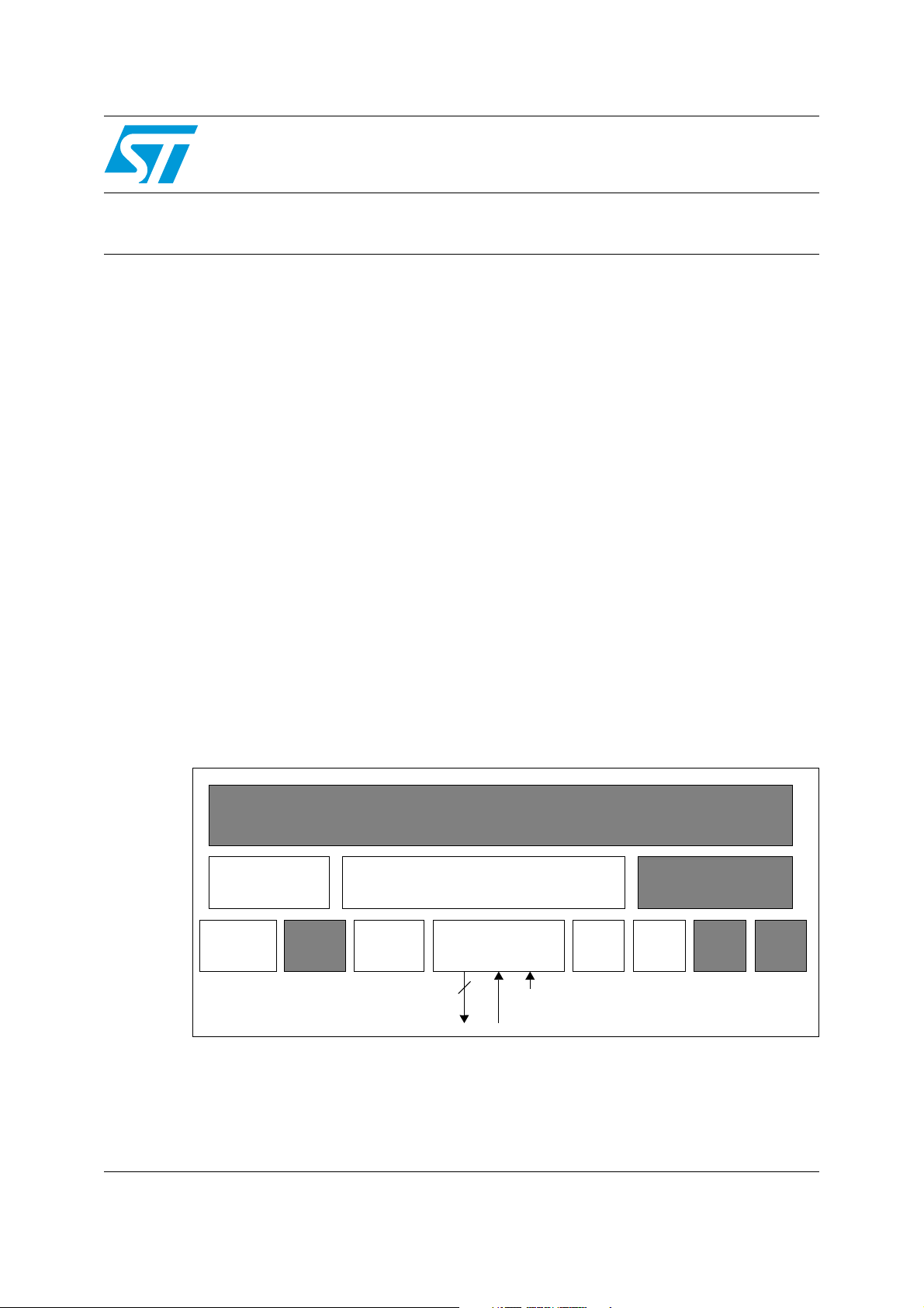
Figure 1. Overall software architecture
APPLICATION LAYER
SLIP
REGULATION
PWMART PORTS
WWDG
3-PHASE SINE WAVE GENERATION
MCO[0..5]
PWM outputs
AC MOTOR DRIVE
MTC SPI
Speed feedback
ADC
Emergency Stop input
COMMUNICATION
PROTOCOL
SCI
16-bit
Timer
July 2007 Rev 3 1/102
www.st.com
Page 2

Contents AN1904
Contents
1 Features . . . . . . . . . . . . . . . . . . . . . . . . . . . . . . . . . . . . . . . . . . . . . . . . . . . 5
2 Working environment set-up . . . . . . . . . . . . . . . . . . . . . . . . . . . . . . . . . . 6
2.1 Development tools . . . . . . . . . . . . . . . . . . . . . . . . . . . . . . . . . . . . . . . . . . . 6
2.1.1 Integrated Development Environments (IDE) . . . . . . . . . . . . . . . . . . . . . 6
2.1.2 Emulators . . . . . . . . . . . . . . . . . . . . . . . . . . . . . . . . . . . . . . . . . . . . . . . . . 6
2.1.3 Programmers . . . . . . . . . . . . . . . . . . . . . . . . . . . . . . . . . . . . . . . . . . . . . . 6
2.1.4 Starter kit . . . . . . . . . . . . . . . . . . . . . . . . . . . . . . . . . . . . . . . . . . . . . . . . . 7
2.2 Library source code . . . . . . . . . . . . . . . . . . . . . . . . . . . . . . . . . . . . . . . . . . 7
2.2.1 Download . . . . . . . . . . . . . . . . . . . . . . . . . . . . . . . . . . . . . . . . . . . . . . . . . 7
2.2.2 File structure . . . . . . . . . . . . . . . . . . . . . . . . . . . . . . . . . . . . . . . . . . . . . . 8
2.3 Utilities . . . . . . . . . . . . . . . . . . . . . . . . . . . . . . . . . . . . . . . . . . . . . . . . . . . . 9
2.3.1 lib.h file . . . . . . . . . . . . . . . . . . . . . . . . . . . . . . . . . . . . . . . . . . . . . . . . . . . 9
2.3.2 Sine wave look-up table spreadsheet . . . . . . . . . . . . . . . . . . . . . . . . . . . 9
2.3.3 HyperTerminal file . . . . . . . . . . . . . . . . . . . . . . . . . . . . . . . . . . . . . . . . . . 9
2.4 Technical literature . . . . . . . . . . . . . . . . . . . . . . . . . . . . . . . . . . . . . . . . . . . 9
3 Getting started with the library using the ST7MC-KIT/BLDC . . . . . . . 10
3.1 Running the motor with the ST7MC control panel . . . . . . . . . . . . . . . . . . 10
3.2 Library configuration file . . . . . . . . . . . . . . . . . . . . . . . . . . . . . . . . . . . . . . 12
3.3 Customizing the files for your ST7MC derivative . . . . . . . . . . . . . . . . . . . 13
3.3.1 Memory mapping with COSMIC toolchain . . . . . . . . . . . . . . . . . . . . . . . 13
3.3.2 Memory mapping with METROWERKS toolchain . . . . . . . . . . . . . . . . . 14
3.3.3 Hardware registers description . . . . . . . . . . . . . . . . . . . . . . . . . . . . . . . 14
3.4 How to define and add a C module . . . . . . . . . . . . . . . . . . . . . . . . . . . . . 15
3.4.1 Using STVD7 release 2.5.x . . . . . . . . . . . . . . . . . . . . . . . . . . . . . . . . . . 15
3.4.2 Using STVD7 release 3.x.x . . . . . . . . . . . . . . . . . . . . . . . . . . . . . . . . . . 16
4 Library functions per software module . . . . . . . . . . . . . . . . . . . . . . . . . 18
4.1 Function description conventions . . . . . . . . . . . . . . . . . . . . . . . . . . . . . . . 18
4.2 Sine wave generation and speed feedback (MTC) . . . . . . . . . . . . . . . . . . 18
4.2.1 Overview . . . . . . . . . . . . . . . . . . . . . . . . . . . . . . . . . . . . . . . . . . . . . . . . 18
4.2.2 List of available functions and interrupt service routines . . . . . . . . . . . . 19
2/102
Page 3

AN1904 Contents
4.2.3 Detailed explanations and customization of MTCparam.h . . . . . . . . . . . 38
4.3 Induction motor scalar control (ACMOTOR) . . . . . . . . . . . . . . . . . . . . . . . 47
4.3.1 Overview . . . . . . . . . . . . . . . . . . . . . . . . . . . . . . . . . . . . . . . . . . . . . . . . 47
4.3.2 List of available functions . . . . . . . . . . . . . . . . . . . . . . . . . . . . . . . . . . . . 47
4.3.3 Detailed explanations and customization of ACMparam.h . . . . . . . . . . 58
4.4 Analog to digital converter . . . . . . . . . . . . . . . . . . . . . . . . . . . . . . . . . . . . 71
4.4.1 Module description . . . . . . . . . . . . . . . . . . . . . . . . . . . . . . . . . . . . . . . . . 71
4.4.2 Synopsis . . . . . . . . . . . . . . . . . . . . . . . . . . . . . . . . . . . . . . . . . . . . . . . . 72
4.4.3 Timing . . . . . . . . . . . . . . . . . . . . . . . . . . . . . . . . . . . . . . . . . . . . . . . . . . 72
4.4.4 Caution . . . . . . . . . . . . . . . . . . . . . . . . . . . . . . . . . . . . . . . . . . . . . . . . . 72
4.4.5 Customizing the ADC module . . . . . . . . . . . . . . . . . . . . . . . . . . . . . . . . 73
4.5 I/O ports . . . . . . . . . . . . . . . . . . . . . . . . . . . . . . . . . . . . . . . . . . . . . . . . . . 73
4.5.1 Push button reading . . . . . . . . . . . . . . . . . . . . . . . . . . . . . . . . . . . . . . . . 73
4.5.2 LEDs . . . . . . . . . . . . . . . . . . . . . . . . . . . . . . . . . . . . . . . . . . . . . . . . . . . 73
4.6 PWM auto reload timer . . . . . . . . . . . . . . . . . . . . . . . . . . . . . . . . . . . . . . . 74
4.6.1 Software timebases working principle . . . . . . . . . . . . . . . . . . . . . . . . . . 74
4.6.2 Timebase use for the AC motor control library and demo program . . . . 75
4.7 Serial communication interface . . . . . . . . . . . . . . . . . . . . . . . . . . . . . . . . 76
4.7.1 Description . . . . . . . . . . . . . . . . . . . . . . . . . . . . . . . . . . . . . . . . . . . . . . . 76
4.7.2 Implementation . . . . . . . . . . . . . . . . . . . . . . . . . . . . . . . . . . . . . . . . . . . 77
4.7.3 Changes vs ST7 library . . . . . . . . . . . . . . . . . . . . . . . . . . . . . . . . . . . . . 77
4.7.4 Customization . . . . . . . . . . . . . . . . . . . . . . . . . . . . . . . . . . . . . . . . . . . . 78
4.7.5 Important notice for hardware implementation . . . . . . . . . . . . . . . . . . . 78
4.8 Nested interrupt controller . . . . . . . . . . . . . . . . . . . . . . . . . . . . . . . . . . . . 78
5 Running the demo programs . . . . . . . . . . . . . . . . . . . . . . . . . . . . . . . . . 80
5.1 Open loop . . . . . . . . . . . . . . . . . . . . . . . . . . . . . . . . . . . . . . . . . . . . . . . . . 81
5.2 Closed loop . . . . . . . . . . . . . . . . . . . . . . . . . . . . . . . . . . . . . . . . . . . . . . . 82
5.3 Using the serial communication interface . . . . . . . . . . . . . . . . . . . . . . . . . 83
5.4 Mainparam.h file description . . . . . . . . . . . . . . . . . . . . . . . . . . . . . . . . . . 84
5.4.1 Start-up parameters . . . . . . . . . . . . . . . . . . . . . . . . . . . . . . . . . . . . . . . . 84
5.4.2 Brake parameters . . . . . . . . . . . . . . . . . . . . . . . . . . . . . . . . . . . . . . . . . 84
5.4.3 Closed-loop slip control . . . . . . . . . . . . . . . . . . . . . . . . . . . . . . . . . . . . . 84
6 Designing your application with the library . . . . . . . . . . . . . . . . . . . . . 85
6.1 Library maintenance . . . . . . . . . . . . . . . . . . . . . . . . . . . . . . . . . . . . . . . . . 85
3/102
Page 4

Contents AN1904
6.2 Incremental system build . . . . . . . . . . . . . . . . . . . . . . . . . . . . . . . . . . . . . 86
6.2.1 Preliminary notice on debugging tools . . . . . . . . . . . . . . . . . . . . . . . . . . 86
6.2.2 Build step1: open loop, low voltage, no motor connected . . . . . . . . . . . 87
6.2.3 Build step2: open loop, rated voltage/power, motor connected . . . . . . . 88
6.2.4 Build step3: open loop, rated power, motor connected with speed
feedback 88
6.2.5 Build step4: closed loop operation . . . . . . . . . . . . . . . . . . . . . . . . . . . . . 88
6.3 Motor control related CPU load in the application . . . . . . . . . . . . . . . . . . 89
6.3.1 Estimation . . . . . . . . . . . . . . . . . . . . . . . . . . . . . . . . . . . . . . . . . . . . . . . 89
6.3.2 Adjustment guidelines . . . . . . . . . . . . . . . . . . . . . . . . . . . . . . . . . . . . . . 89
Appendix A Appendix. . . . . . . . . . . . . . . . . . . . . . . . . . . . . . . . . . . . . . . . . . . . . . . 90
A.1 Flowcharts. . . . . . . . . . . . . . . . . . . . . . . . . . . . . . . . . . . . . . . . . . . . . . . . . 90
A.1.1 MTC_U_CL_SO_IT interrupt routine . . . . . . . . . . . . . . . . . . . . . . . . . . . 90
A.1.2 MTC_C_D_IT interrupt routine . . . . . . . . . . . . . . . . . . . . . . . . . . . . . . . . 91
A.1.3 MTC_GetRotorFreq function. . . . . . . . . . . . . . . . . . . . . . . . . . . . . . . . . . 92
A.1.4 GetLastTachoPeriod function . . . . . . . . . . . . . . . . . . . . . . . . . . . . . . . . . 93
A.1.5 GetAvrgTachoPeriod function . . . . . . . . . . . . . . . . . . . . . . . . . . . . . . . . . 94
A.1.6 MTC_StartBraking function. . . . . . . . . . . . . . . . . . . . . . . . . . . . . . . . . . . 95
A.1.7 MTC_Brake function state diagram . . . . . . . . . . . . . . . . . . . . . . . . . . . . 96
A.1.8 MTC_StopBraking function. . . . . . . . . . . . . . . . . . . . . . . . . . . . . . . . . . . 96
A.1.9 ACM_InitSoftStart function . . . . . . . . . . . . . . . . . . . . . . . . . . . . . . . . . . . 97
A.1.10 ACM_SoftStart function . . . . . . . . . . . . . . . . . . . . . . . . . . . . . . . . . . . . . 98
A.1.11 Open Loop motor control demo program . . . . . . . . . . . . . . . . . . . . . . . . 99
A.2 Selni motor characteristics . . . . . . . . . . . . . . . . . . . . . . . . . . . . . . . . . . . 100
7 Revision history . . . . . . . . . . . . . . . . . . . . . . . . . . . . . . . . . . . . . . . . . . 101
4/102
Page 5

AN1904 Features
1 Features
ST7MC Library Version 1.0.1 Overview (CPU running at 8 MHz):
● Stator Frequency Range: From 0.2 Hz up to 680.0 Hz (see Section on page 44) with
resolution depending on PWM frequency (typically ~0.1Hz)
● Voltage Resolution: 8-bit modulation index
● 9 to 10-bit PWM generation for sine wave (typical resolution in inaudible PWM range)
● PWM Frequency: can be set by default to 1.95, 3.9, 7.8, 12.5 and 15.66 kHz, with
centred pattern PWM generation
● Brake capabilities (DC current injection)
● Speed reversal
● Tacho generator Speed acquisition
● Speed regulation and control routines for speed profile management
● CPU Load (sine wave generation only) around 20%, adjustable (see Section ). Total
CPU load (including closed loop control) is typically around 30% for a standard
application (see Section 6.3)
● Free C source code and spreadsheet for look-up tables
The 12.5 kHz switching frequency is proposed by default, providing a PWM resolution close
to 10-bit with a 16-MHz CPU clock. In addition, this frequency is a good compromise
between the reduction of switching losses and acoustic noise (rejected in the inaudible
range due to centred mode PWM patterns).
Note: These figures are for information only; this software library may be subject to changes
depending on the use of the final application and peripheral resources. It must be noted that
it was built using robustness-oriented structures, therefore preventing the speed or code
size from being fully optimized.
Ta bl e 1 below summarizes the memory required by the software library, as it is delivered.
These metrics include non motor control related code, implemented for demo purposes
(such as ADC management, software timebases, etc.). These must therefore be considered
only as indicative figures, which will be lower in the final application.
Table 1. Memory size metrics
ROM (bytes) RAM (bytes)
Cosmic 5.2b Metrowerks 1.1 Cosmic 5.2b Metrowerks 1.1
Closed Loop 4943 5729 136 161
Open loop 3840 4361 108 130
5/102
Page 6

Working environment set-up AN1904
2 Working environment set-up
This section presents the available material that is needed to start working with the ST7MC
and the library discussed in this document.
2.1 Development tools
2.1.1 Integrated Development Environments (IDE)
This library has been compiled using Cosmic & Metrowerks C compilers, launched with
STVD7 release 2.5.4 (ST Visual Debugger) and STVD7 release 3.x.x.
A complete software package consists of:
● An IDE interface: ST’s proprietary STVD7 (free download available on internet:
www.stmcu.com), or third party IDE (e.g. Softec Microsystems’ STVD7 for InDARTSTX).
● A third party C-compiler: either Cosmic or Metrowerks (if needed, time limited
evaluation versions can be get upon request).
The choice of the C Toolchain is left to the appreciation of the user. Both COSMIC and
METROWERKS are fully supported, and the dedicated workspace (compatible with
‘STVD7’ & ‘STVD7 for Indart’) can be directly opened in the root of the library installation
folder (AC_Metrowerks.wsp, AC_Cosmic.wsp, acmotor.stw).
2.1.2 Emulators
Two types of real-time development tools are available for debugging applications using
ST7MC:
● In-circuit debugger from Softec (sales type: STXF-INDART/USB).
The inDART-STX from Softec Microsystems is both an emulator and a programming
tool. This is achieved using the In-circuit debug module embedded on the MCU. The
real-time features of the Indart include access to the working registers and 2 breakpoint
settings. However trace is not available.
● ST7MDT50-EMU3 emulator
Full-featured emulator: real-time with trace capability, performance analysis, advanced
breakpoints, light logical analyser capabilities, etc. It can also be a programming tool
when used with the delivered ICC ADDON module (select STMC-ICC as hardware
target in STVP7). This ICC-ADDON module allows In-Circuit-Debugging with STVD7.
2.1.3 Programmers
In order to program an MCU with the generated S19 file, you should also install the ST
Visual Programmer software (please visit our internet web-site) and use a dedicated
programming interface (stick programmer for example for In-Circuit-Programming). The
Visual Programming tool provides an easy way to erase, program and verify the MCU
content.
Please note that the inDART-STX from Softec Microsystems is also a programming tool
(installation of DataBlaze Programmer software is required).
6/102
Page 7
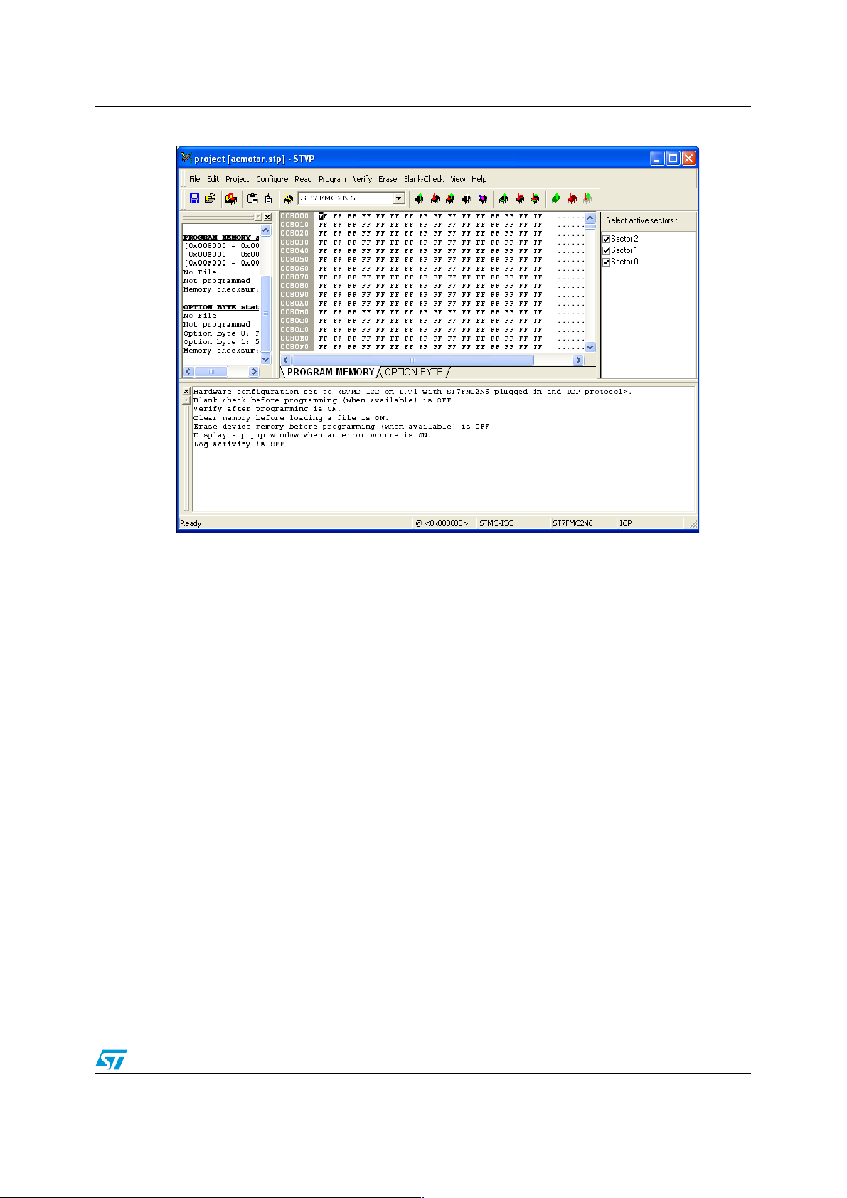
AN1904 Working environment set-up
Figure 2. STVisual Programmer software (STVP7)
2.1.4 Starter kit
The present software library was fully validated using the main hardware board (a complete
inverter and control board) included in ST7MC-KIT/BLDC starter kit, and the demonstration
AC motor from SELNI (Sales type ST7MC-MOT/IND). See Section A.2 on page 100 for
electrical specifications of this motor. The ST7MC-KIT/BLDC starter kit also includes a lowcost inDART hardware emulator, making this tool an ideal set for starting a project and
evaluating/using the library. Finally, the graphical user interface included in the starter kit
(ST7MC Control Panel) is primarily intended to run motors from a PC for testing and demo
purposes, and is also able to generate library configuration files, with defines corresponding
to your own motor. This makes the first implementation of this library significantly easier.
See Section 4 of this document for details.
Therefore, for rapid implementation and evaluation of the software discussed in this
application note, it is recommended to acquire the ST7MC-KIT/BLDC starter kit and one of
the two compatible C-toolchain (or at least time limited evaluation versions).
2.2 Library source code
2.2.1 Download
The complete source files are available for free on ST website (www.stmcu.com), in the
Technical Literature and Support Files section, as a zip file. This library is also copied by
default on the hard-disk when installing the ST7MC Control Panel from Softec micro
systems, or available on www.softecmicro.com, in the Downloads section, software part
(AK-ST7FMC System Software).
7/102
Page 8

Working environment set-up AN1904
Caution: It is highly recommended to check for the latest releases of the library before starting a new
development, and then verify the release notes from time to time to be aware of new
features that might be of interest for the project. Registration mechanisms are also available
on the web sites of ST and Softec Microsystems to get automatically update information.
2.2.2 File structure
Once the files are unzipped, the following library structure appears, depending on the
toolchain.
● Library release 1.0.0
This release only supports STVD7 2.5.x workspace; this IDE does not provide C
builder capabilities. All build information is provided in makefiles and linker command
files, in dedicated folders: config\Cosmic and config\Metrowerks (see Figure 3). Object
files are also provided in dedicated folders.
Figure 3. Library structure for release 1.0.0
ACmotor \ config
\ object
\ source
● Library release 1.0.1
\ cosmic
\ metrowerks
\ cosmic
\ metrowerks
This library contains the workspace for both the STVD7 2.5.x and STVD7 3.x IDEs.
Two separate sets of folders are provided to differentiate object and configuration files,
with a common set of source files (see Figure 4).
This is to ensure the compatibility with STVD7 for inDART-STX, based on STVD7 2.5.3.
Figure 4. Library structure for release 1.0.1
ACmotor_1.0.1
\ config
\ object
\ Debug
\ Release
\ Source
\ Utilities
\ cosmic
\ metrowerks
\ cosmic
\ metrowerks
For STVD7_3.x
For STVD7_2.5.x
8/102
Page 9

AN1904 Working environment set-up
2.3 Utilities
2.3.1 lib.h file
The purpose of this header file is to provide useful macros and type re-definitions which will
be used throughout the entire library:
● Re-definition of data types using the following convention: a first letter indicating if a
variable is signed (s) or unsigned (u), plus a number indicating the number of available
bits (for instance: u8, s16, etc.),
● Defines for assembly mnemonics used in C source code: Nop(), Trap(),...
● Common macros used for bit-level access (SetBit, ClrBit,...), to get the dimension of an
array (DIM[x]), etc.
2.3.2 Sine wave look-up table spreadsheet
A sine3.xls Excel file is provided with the library, in the \utilities folder. It contains the data
and calculations necessary to re-generate the sine wave reference look-up table. This lookup table includes 3rd harmonics and is therefore not suitable as it is for bi-phase motor
control. PWM frequency set-up on page 39.
2.3.3 HyperTerminal file
An AC Library.ht file is also provided in the \utilities folder to set-up the HyperTerminal
software when the RS232 communication is enabled. Serial communication interface on
page 76.
2.4 Technical literature
More information can be found on the ST website (www.st.com).
9/102
Page 10

Getting started with the library using the ST7MC-KIT/BLDC AN1904
3 Getting started with the library using the ST7MC-
KIT/BLDC
There a two ways to get started with this software library.
■ The first method is to edit (with your motor specific features) and compile the modules
described in Section 4 of this application note. Then program ST7MC and run your motor
using the ST7MC-KIT/BLDC Starter-kit hardware or your own design.
■ The second method is to use the ST7MC-KIT/BLDC Starter-kit and follow this process:
– run and fine tune motor parameters with the ST7MC Control Panel,
– generate *.h files and select/save manually key parameters,
– edit some of the .h files with run-time parameters collected with the GUI (see
Section 4.2.3 and Section 4.3.3 for details),
– compile, link and program the ST7MC,
– run the motor.
This second method is highly recommended and is described below.
3.1 Running the motor with the ST7MC control panel
As a starting point, the open loop mode can be used for the first trials. Low voltage values
can be used for safety and then increased smoothly step by step. Incremental system build
on page 86 for details.
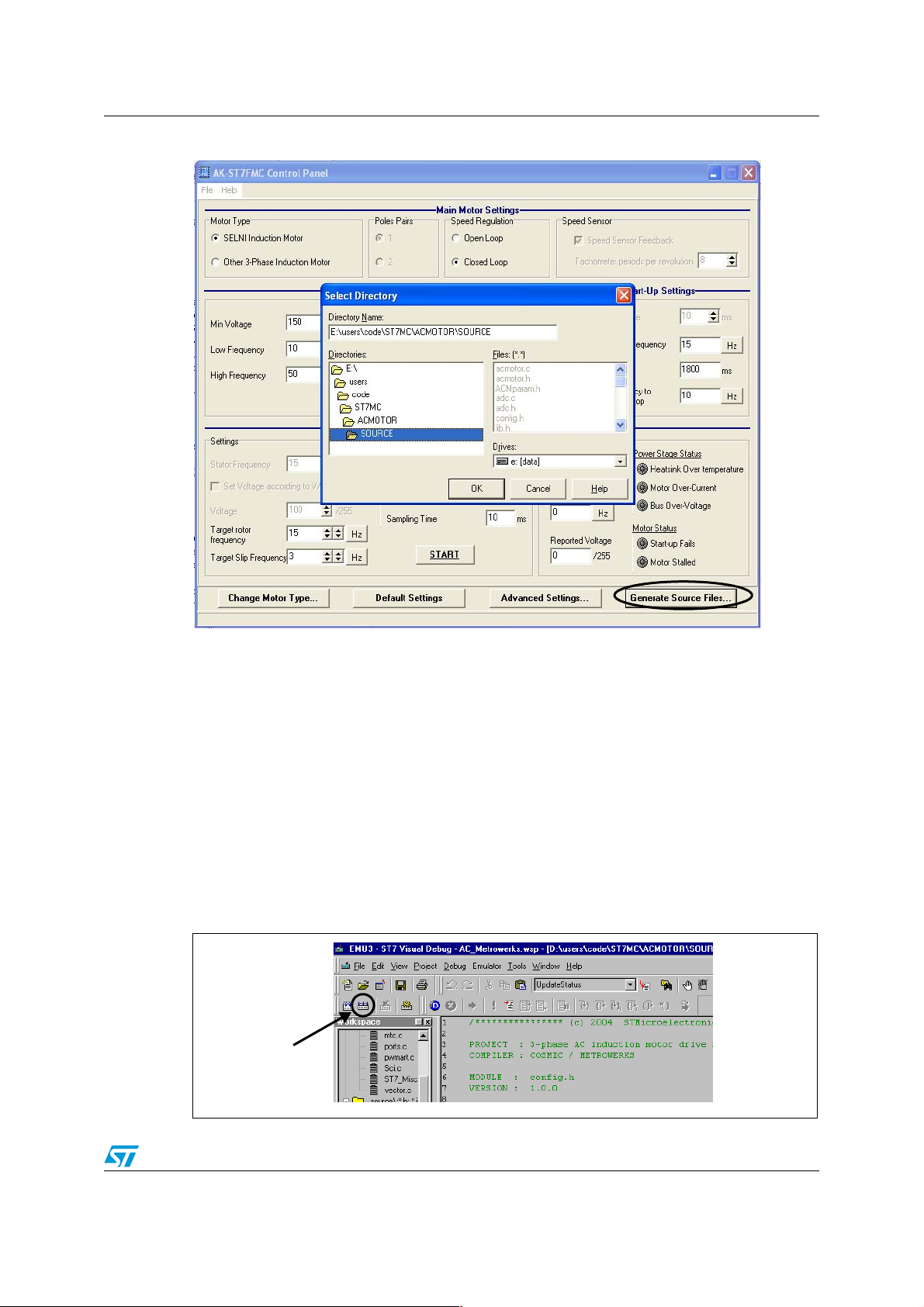
Once the motor settings have been finely adjusted (whatever the driving mode, open or
closed loop), the parameters have to be imported into the stand-alone library. Simply click
on ‘Generate *.h Files’ and select the source directory of the stand-alone library: see
Figure 5
10/102
Page 11
AN1904 Getting started with the library using the ST7MC-KIT/BLDC
Figure 5. . ST7MC Control Panel: library header files generation
This interface generates 3 header files containing the motor and application parameters plus
a file with conditional compilation keys for library re-build (see Section 3.2):
● MTCparam.h contains parameters of routines directly related to the motor controller
peripheral, mainly PWM, sine wave generation and speed feedback processing (see
Section 4.2.3 on page 38),
● ACMparam.h contains parameters related to the motor and the load, such as V/f curve
and speed regulation (see Section 4.3.3 on page 58),
● Mainparam.h contains some application/demo specific features (see Section 5.4 on
page 84).
Once the above files have been generated, the whole library must be re-built. The library
and its demo program will then include the new settings automatically.
To launch the compilation, click on the ’rebuild all’ icon of STVD7: see Figure 6
Figure 6. Rebuilding the whole application with STVD7
Rebuild
11/102
Page 12

Getting started with the library using the ST7MC-KIT/BLDC AN1904
3.2 Library configuration file
The purpose of this file is to declare the compiler conditional compilation keys which will be
used throughout the entire library compilation process, to:
● define the AC motor driving mode: open / closed loop (see Section 5 and Section 5.3),
● define the PWM resolution (needed to define the PWM frequency range, see Section ),
● enable or disable the RS232 communication (see Using the serial communication
interface on page 83),
● enable or disable the PI parameters tuning (see Regulation tuning procedure on
page 62).
Below are the compilation key definitions in config.h:
// Define here the desired control type
// 0 -> Open loop
// 1 -> Closed loop
#define CONTROL1
//-------------------------------------------------------------------------
// Define here the chosen PWM resolution (linked to PWM switching frequency)
// 0 -> 9-bit: 1.95kHz, 3.9kHz, 7.8kHz, 15.66kHz: cf. "MTCparam.h"
// 1 -> 10-bit: 12.5 kHz
#define PWM_RESOLUTION 1
//-------------------------------------------------------------------------
// Define here the way the closed loop parameters (Kp, Ki) are set
// if this label is commented, Kp and Ki are set according to a look-up table
// defined in ACMparam.h.
//#define PI_PARAM_TUNING
//-------------------------------------------------------------------------
// Define here if you want to use the SCI interface to monitor some internal
// variables during run time
// IMPORTANT NOTE: As communication is done by polling, this will decrease
// the sampling rate of the PI Speed controller
#define ENABLE_RS232
12/102
Page 13

AN1904 Getting started with the library using the ST7MC-KIT/BLDC
3.3 Customizing the files for your ST7MC derivative
Figure 7. Memory map
0000h
007Fh
0080h
067Fh
0680h
0FFFh
1000h
FFDFh
FFE0h
FFFFh
HW Registers
768/384 Bytes)
Program Memory
(60K, 48K, 32K, 24K, 8K)
Interrupt & Reset Vectors
RAM
(1536/1024
Reserved
0080h
00FFh
0100h
01FFh
0200h
01FFh
or 037Fh
or 047Fh
or 067Fh
Short Addressing
RAM (zero page)
256 Bytes Stack
16-bit Addressing
RAM
1000h
4000h
8000h
A000h
E000h
FFFFh
60 KBytes
48 KBytes
32 KBytes
24 KBytes
8 KBytes
The ST7MC memory is shown on Figure 7. The memory arrangement may vary depending
on the type of the MCU. Please refer to the ST7MC datasheet for more information.
The library is dedicated by default to the ST7FMC2N6B6 MCU (SDIP56, 32KB Flash, 1K
RAM). In order to target another ST7MC MCU, you may need to modify the C-toolchain
configuration files. Here’s a basic example of what has to be done prior to any other
modifications.
The above example is based on the ST7FMC2S4 MCU (TQFP 44, 16K Flash, 768 Bytes
RAM).
3.3.1 Memory mapping with COSMIC toolchain
Go to \config\Cosmic, edit 32K.lkf and check the following lines, in ‘SEGMENT
DEFINITION’:
# SEGMENT DEFINITION (.text, .const,.data,.bss,.bsct,.ubsct are c compiler
predefined sections)
+seg .text -b0x8000 -m0x8000 -nCODE -sROM # executable code
+seg .const -aCODE -it -sROM # constants and strings
+seg .bsct -b0x0080 -m0x007F -nZPAGE -sRAM #initialized variables in SHORT range
+seg .ubsct -aZPAGE -nUZPAGE -sRAM # uninitialized variables in SHORT range
+seg .share -aUZPAGE -is -sRAM # shared segment (defined when using compact or
memory models only)
+seg .data -b0x0200 -m0x27F -nIDATA -sRAM # NO initialized variables
+seg .bss -aIDATA -nUDATA -sRAM # uninitialized variables
This section contains the memory placement for the object files, listed just after this
declaration.
In order to enter the memory mapping of the ST7FMC2S4, the size of ROM and RAM
memory have to be changed (32K -> 16K Flash, 1K RAM -> 768 Bytes RAM). For ROM:
13/102
Page 14

Getting started with the library using the ST7MC-KIT/BLDC AN1904
+seg .text -b0xc000 -m0x3fe0 -nCODE -sROM # executable code
(where 0xc000 is the new starting address of the program memory and 0x3fe0 the size in
bytes). For RAM:
+seg .bss -b0x0200 -m0x0180 -nUDATA -sRAM # uninitialized variables
(where 0x0180 is the new size of the 16 bit addressing RAM memory).
3.3.2 Memory mapping with METROWERKS toolchain
Go to \config\Metrowerks, edit acmotor.prm and check the following lines:
SECTIONS
ZRAM = READ_WRITE 0x0080 TO 0x00FF;
RAM = READ_WRITE 0x0200 TO 0x047F;
ROM = READ_ONLY 0x8000 TO 0xFFDF;
This part of the prm file contains the memory locations of pages declared at the end of the
file.
To modify the memory size for the ST7FMC2S4, ROM and RAM memory settings have to
be changed (32K -> 16K Flash, 1K RAM -> 768 Bytes RAM):
ROM = READ_ONLY 0xC000 TO 0xDFFF;
(where 0xc000 is the new starting address of the program memory),
RAM = READ_WRITE 0x0200 TO 0x027F; // 16 bit addressing RAM
(where 0x027F is the end address of the 16 bit addressing RAM memory).
Caution: The application layer has been written for the STMFC2NB6. Using a different ST7MC sales
type can imply the need to do some modifications to the library, according to the available
features (some of the I/O ports are not present on low-pin count packages). Please refer to
the datasheet for details.
3.3.3 Hardware registers description
The library is based on the ST7FMC2N6.h file, which contains the hardware registers
declarations and memory mapping for the ST7FMC2N6. It also contains most of the bit
masks for the peripherals, at the exception of some Motor Controller bits and bitfields
described in mtc_bits.h.
The ST7FMC2N6.h is provided by default with the STVD7 release 3.x.x toolchain, usually
in:
C:\Program Files\STMicroelectronics\st7toolset\include
All other ST7MC derivative descriptions can be found in this folder, from the ST7FMC1K2 to
the ST7FMC2M9. The name of the corresponding header file will have to be changed in the
config.h file.
14/102
Page 15

AN1904 Getting started with the library using the ST7MC-KIT/BLDC
3.4 How to define and add a C module
This chapter describes how to define and declare a new module in a project based on the
library. The example is based on the addition of 2 files: ‘my_file.c’ and the corresponding
header file ‘my_file.h’.
The first step is the creation of these files. Existing files can be copied, pasted and renamed,
or created by clicking on the ‘new files’ icon and then saving them with the right extension
(*.c or *.h).
Three files (two source and one object) have to be declared in the toolchain configuration
files.
3.4.1 Using STVD7 release 2.5.x
COSMIC compiler
COSMIC compiler is launched using a makefile (acmotor.mak) and the linker gets
information from the linker command file 32K.lkf file. These two files need to be modified.
In 32.lkf, the new object file has to be added in the common object file list, or apart from this
object list with correct settings (for instance for interrupt vectors or constants that need to be
at fixed location, see documentation of C compiler for details).
# OBJECT FILES
..\..\object\cosmic\main.o
...
..\..\object\cosmic\my_file.o
...
# OBJECT FILES END
In acmotor.mak, ‘my_file.c’ has to be added in the C source file list:
C_SRC = \
main.c \
acmotor.c \
... \
my_file.c \
... \
vector.c
and the list of dependencies has to be updated accordingly:
# RULES FOR MAKING THE OBJECT FILES:
main.o: main.c lib.h ports.h adc.h pwmart.h Sci.h mtc.h acmotor.h
config.h Mainparam.h ST7FMC2N6.h
$(CC) ..\..\source\main.c
15/102
Page 16

Getting started with the library using the ST7MC-KIT/BLDC AN1904
...
my_file.o: my_file.c my_file.h lib.h ST7FMC2N6.h ...
$(CC) ..\..\source\my_file.c
METROWERKS compiler
For METROWERKS users, modifications have to be done in acmotor.prm and acmotor.mak
files. In the makefile, the new object file my_file.o has to be added in the ‘Object file list’
section and the corresponding dependencies have to be set in the ‘Application files’ section:
# ----------------------------- OBJECT FILES LIST -----------------------------
OBJ_LIST = main.o mtc.o ... my_file.o
...
# --------------------------- APPLICATION FILES ------------------------------
main.o : $(ENV) main.c lib.h ports.h adc.h pwmart.h sci.h mtc.h acmotor.h \
config.h MainParam.h ST7FMC2N6.h
$(CC) main.c
my_file.o : $(ENV) my_file.c my_file.h lib.h ST7FMC2N6.h ...
$(CC) my_file.c
In acmotor.prm the new object file has to be added in the ‘Project module list’ section:
/*** PROJECT MODULE LIST ***/
NAMES
main.o
mtc.o
...
my_file.o
...
start07.o
ansi.lib
END
3.4.2 Using STVD7 release 3.x.x
The procedure is far easier with STVD7 3.x.x, as the makefile and linking command files are
automatically generated.
In the workspace window, just right click on the selected project (either cosmic or
metrowerks) and select “Add Files to Project”. You’ll be asked to select source file.
When rebuilding the library, the configuration files will be updated accordingly.
16/102
Page 17

AN1904 Getting started with the library using the ST7MC-KIT/BLDC
Figure 8. Adding a source file using STVD7 3.x.x
17/102
Page 18

Library functions per software module AN1904
4 Library functions per software module
4.1 Function description conventions
The functions are described in the format given below:
Synopsis This section lists the required include files and prototype declarations.
Description The functions are described with a brief explanation on how they are
executed.
Input In few lines, the format and units are given.
Returns Gives the value or error code returned by the function.
Caution Indicates the limits of the function or specific requirements that must be
taken into account during library integration.
Warning Indicates important points that must be taken into account to prevent
hardware failures.
Functions called Allows to prevent conflicts due to the simultaneous use of resources.
Duration The approximate duration of the routine. This is performed using the
maximum CPU clock frequency (8 MHz) without interrupts if not notified.
Slight variations may be expected when changing compiler, options,
memory models,...
Code example Indicates the proper way to use the function if there are certain
prerequisites (interrupt enabled, etc.).
Some of these sections may not be included if not applicable (no parameters, obvious use,
etc.).
4.2 Sine wave generation and speed feedback (MTC)
4.2.1 Overview
The “mtc.c” module is intended to handle all motor control functionalities directly linked to
the motor control peripheral hardware (initialization or run-time accessed registers, interrupt
service routine).
It can be seen as an interface between the AC motor control specific module and the low
level control routines having direct influence on the hardware (PWM outputs, speed sensor,
Emergency Shutdown pin).
It contains, among other functions:
● basic setup / control functions for the Motor Controller Peripheral (MTC),
● Sine wave generation (through PWM interrupt processing),
● DC current braking,
● Direction reversal,
● speed acquisition related interrupts and functions.
The prototype functions are located in the “mtc.h” header file.
18/102
Page 19

AN1904 Library functions per software module
4.2.2 List of available functions and interrupt service routines
The following is a list of available functions as listed in the mtc.h header file.
MTC_ResetPeripheral . . . . . . . . . . . . . . . . . . . . . . . . . . . . . . . . . . . . . . . . on page 20
MTC_InitPeripheral . . . . . . . . . . . . . . . . . . . . . . . . . . . . . . . . . . . . . . . . . . on page 20
MTC_InitSineGen . . . . . . . . . . . . . . . . . . . . . . . . . . . . . . . . . . . . . . . . . . . on page 20
MTC_EnableMCOutputs . . . . . . . . . . . . . . . . . . . . . . . . . . . . . . . . . . . . . . on page 21
MTC_DisableMCOutputs. . . . . . . . . . . . . . . . . . . . . . . . . . . . . . . . . . . . . . on page 21
MTC_CheckEmergencyStop . . . . . . . . . . . . . . . . . . . . . . . . . . . . . . . . . . . on page 22
MTC_ClearEmergencyStop. . . . . . . . . . . . . . . . . . . . . . . . . . . . . . . . . . . . on page 22
MTC_StartBraking . . . . . . . . . . . . . . . . . . . . . . . . . . . . . . . . . . . . . . . . . . . on page 23
MTC_Brake . . . . . . . . . . . . . . . . . . . . . . . . . . . . . . . . . . . . . . . . . . . . . . . . on page 24
MTC_StopBraking . . . . . . . . . . . . . . . . . . . . . . . . . . . . . . . . . . . . . . . . . . . on page 25
MTC_Toggle_Direction . . . . . . . . . . . . . . . . . . . . . . . . . . . . . . . . . . . . . . . on page 26
MTC_Set_ClockWise_Direction . . . . . . . . . . . . . . . . . . . . . . . . . . . . . . . . on page 26
MTC_Set_CounterClockWise_Direction . . . . . . . . . . . . . . . . . . . . . . . . . . on page 26
MTC_GetRotationDirection . . . . . . . . . . . . . . . . . . . . . . . . . . . . . . . . . . . . on page 26
MTC_GetVoltage . . . . . . . . . . . . . . . . . . . . . . . . . . . . . . . . . . . . . . . . . . . . on page 27
MTC_GetStatorFreq . . . . . . . . . . . . . . . . . . . . . . . . . . . . . . . . . . . . . . . . . on page 27
MTC_GetSlip . . . . . . . . . . . . . . . . . . . . . . . . . . . . . . . . . . . . . . . . . . . . . . . on page 27
MTC_InitTachoMeasure . . . . . . . . . . . . . . . . . . . . . . . . . . . . . . . . . . . . . . on page 28
MTC_StartTachoFiltering. . . . . . . . . . . . . . . . . . . . . . . . . . . . . . . . . . . . . . on page 28
MTC_ValidSpeedInfo. . . . . . . . . . . . . . . . . . . . . . . . . . . . . . . . . . . . . . . . . on page 29
MTC_GetRotorFreq . . . . . . . . . . . . . . . . . . . . . . . . . . . . . . . . . . . . . . . . . . on page 30
MTC_UpdateSine . . . . . . . . . . . . . . . . . . . . . . . . . . . . . . . . . . . . . . . . . . . on page 31
GetLastTachoPeriod . . . . . . . . . . . . . . . . . . . . . . . . . . . . . . . . . . . . . . . . . on page 32
GetAvrgTachoPeriod . . . . . . . . . . . . . . . . . . . . . . . . . . . . . . . . . . . . . . . . . on page 32
MTC_U_CL_SO_IT . . . . . . . . . . . . . . . . . . . . . . . . . . . . . . . . . . . . . . . . . . on page 33
MTC_C_D_IT. . . . . . . . . . . . . . . . . . . . . . . . . . . . . . . . . . . . . . . . . . . . . . . on page 34
MTC_R_Z_IT . . . . . . . . . . . . . . . . . . . . . . . . . . . . . . . . . . . . . . . . . . . . . . . on page 35
MCES_SE_IT . . . . . . . . . . . . . . . . . . . . . . . . . . . . . . . . . . . . . . . . . . . . . . on page 36
SET_MTC_PAGE . . . . . . . . . . . . . . . . . . . . . . . . . . . . . . . . . . . . . . . . . . . on page 37
ToCMPxL. . . . . . . . . . . . . . . . . . . . . . . . . . . . . . . . . . . . . . . . . . . . . . . . . . on page 37
ToCMPxH . . . . . . . . . . . . . . . . . . . . . . . . . . . . . . . . . . . . . . . . . . . . . . . . . on page 37
MTC_EnableClock. . . . . . . . . . . . . . . . . . . . . . . . . . . . . . . . . . . . . . . . . . . on page 37
MTC_DisableClock . . . . . . . . . . . . . . . . . . . . . . . . . . . . . . . . . . . . . . . . . . on page 37
19/102
Page 20

Library functions per software module AN1904
MTC_ResetPeripheral
MTC_InitPeripheral
MTC_InitSineGen
Synopsis #include "mtc.h"
void MTC_ResetPeripheral(void);
void MTC_InitPeripheral(void);
void MTC_InitSineGen(void);
Description The purpose of these three functions is to set-up the Motor Controller
peripheral and to initialize the software variables needed for sine wave
generation.
MTC_ResetPeripheral
Resets the whole circuitry of the Motor Controller peripheral of the ST7MC,
as it is found after a microcontroller RESET, with the sole exception of the
MDTG and MPOL write-once registers (see datasheet for details).
MTC_InitPeripheral
Performs the initialization of the Motor Controller peripheral hardware
registers, for the sine wave general parameters (such as PWM frequency,
output polarity, deadtime, interrupts,...) and speed feedback processing
(tacho input selection, edge sensitivity,...). It also starts the 12-bit PWM
timer and the tacho dedicated timer (MTIM:MTIML). All required motor
control related interrupts are unmasked upon completion of this routine.
MTC_InitSineGen
Initialization of software variables needed for sine wave generation and
used in the PWM update interrupt routine. Ensures that once the PWM
update interrupts will have been enabled, the sine wave generated will
have a null voltage and that stator frequency change will be taken into
account.
Duration 2.75µs for MTC_ResetPeripheral, 26µs for MTC_InitPeripheral and 392µs
for MTC_InitSineGen.
Note: These three functions do not need to be called by the user application, as they are managed
by the ACM_Init function.
20/102
Page 21

AN1904 Library functions per software module
MTC_EnableMCOutputs
MTC_DisableMCOutputs
Synopsis #include "mtc.h"
void MTC_EnableMCOutputs(void);
void MTC_DisableMCOutputs (void);
Description The purpose of these two functions is to configure the MCOx outputs of the
ST7MC.
MTC_EnableMCOutputs
Enables the MCOx pins to output the PWM signals of the Motor Controller
Peripheral. This function must be called to re-start PWM generation after
an emergency shutdown (low state on MCES pin).
MTC_DisableMCOutputs
This function immediately disconnects the MCOx PWM outputs pins from
the Motor Controller peripheral. It resets the MOE bit in the MCRA register,
thus causing the MCOx pins to be in their reset configuration, as defined in
the options bytes (high impedance or low impedance high/low state).
Duration 2.15 µs
See also ST7MC Datasheet: MTC chapter.
21/102
Page 22

Library functions per software module AN1904
MTC_CheckEmergencyStop
MTC_ClearEmergencyStop
Synopsis #include "mtc.h"
BOOL MTC_CheckEmergencyStop(void);
void MTC_ClearEmergencyStop(void);
Description The purpose of these two functions is to provide to the higher level control
modules information regarding an Emergency Stop of the PWM operation.
This information is returned by a function call once the related interrupt
routine has been serviced. For users requiring immediate action taken as
soon as the NMCES event occurs, the interrupt routine needs to be used
directly (see MCES_SE_IT on page 36).
MTC_CheckEmergencyStop
Indicates if PWM outputs are enabled or not, and therefore if MOE bit
(Main Output Enable) has been cleared by hardware, upon Emergency
Stop event.
MTC_ClearEmergencyStop
Resets the boolean where the emergency Stop interrupt routine execution
was recorded, regardless of the MOE bit state.
Returns MTC_CheckEmergencyStop returns a boolean parameter, TRUE if an
emergency Stop interrupt has been serviced, causing the PWM outputs to
be disabled.
Duration 2.5 µs
See also ST7MC Datasheet: Motor Controller section, Emergency feature section.
MCES_SE_IT on page 36.
22/102
Page 23

AN1904 Library functions per software module
MTC_StartBraking
Synopsis #include "mtc.h"
void MTC_StartBraking(u16 DutyCycle);
Description The purpose of this function is to start the braking sequence by initializing
the brake related flags, stopping the PWM interrupts generation, disabling
the PWM outputs and starting the timebase needed for stator
demagnetization. It also set the sine wave voltage to zero in case the
braking sequence is interrupted and sine wave generation is re-started.
Braking is obtained by sinking DC current in one motor winding. The
braking torque is also defined in this function, in direct relation with the duty
cycle applied to one of the motor winding, the other two phases being
grounded (low side switches continuously ON).
Input Duty cycle value is entered as a u16 variable without unit: to get the
applied duty cycle, the value has to be compared to the CMP0 register
value, defining the PWM frequency.
For instance, for a PWM frequency of 12.5kHz, CMP0 = 639 (refer to the
Section for details). If the DutyCycle variable is set to 32, this will lead to
an applied duty cycle of 32/(639+1) = 10% (with center-aligned patterns).
As the AC motor is driven in voltage mode, there’s no way to define a
relationship between this duty cycle, the braking torque and the current
feed in the motor. This duty cycle will therefore have to be defined
empirically.
Functions called MTC_UpdateSine, MTC_DisableMCOutputs, ART_SetSequenceDuration.
Duration 70 µs
See also MTC_Brake, MTC_StopBraking, flowchart on A.1.6 on page 95,
Section 5.4 on page 84 and Section on page 45 for timings set-up.
23/102
Page 24
Library functions per software module AN1904
MTC_Brake
Synopsis #include "mtc.h"
void MTC_Brake(void);
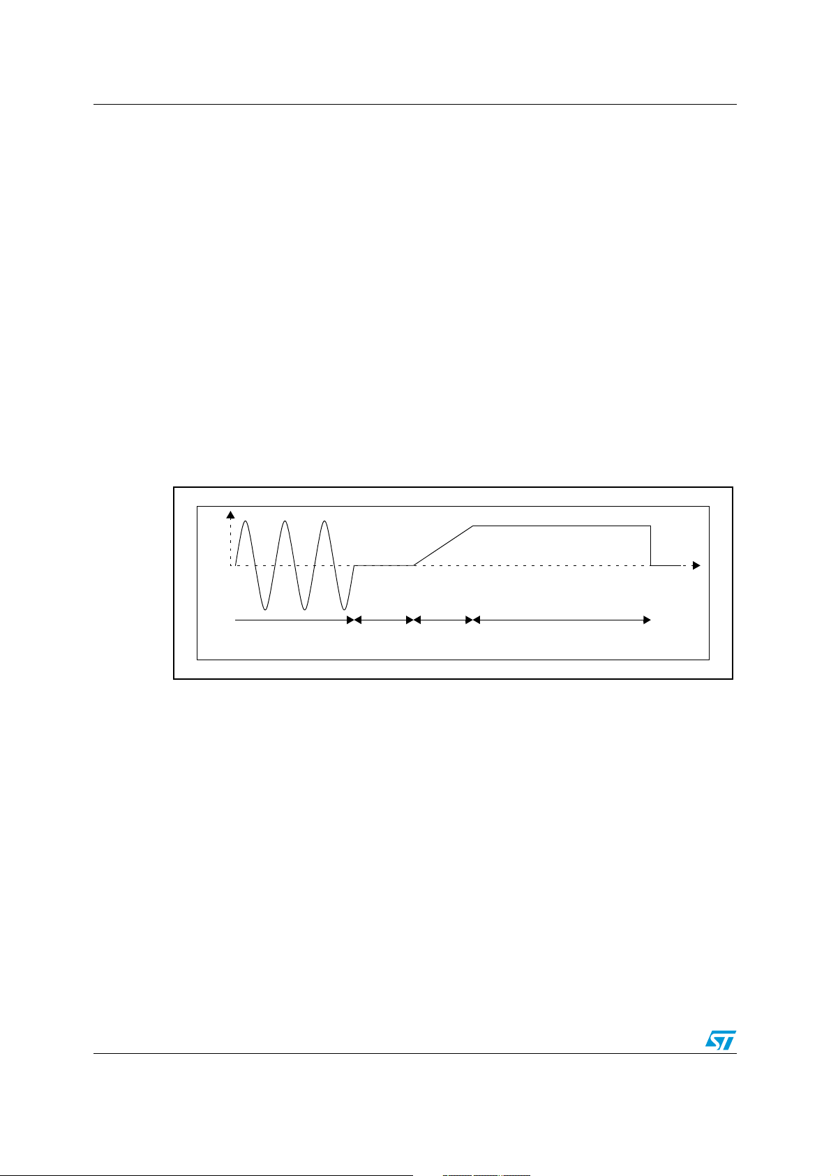
Description The purpose of this function is to handle the three phases of the braking
sequence, as represented below in Figure 9
1. A waiting time for the Stator current to decrease down to zero
(demagnetization), all PWM being OFF.
2. A smooth DC current increase up to expected value to avoid inrush
current in the stator.
3. The sustaining of this current permanently up to the MTC_StopBraking
function call.
Figure 9. . Current waveform during brake sequence
Current
Motor running
Rotor
demag.
Current
settle
Active brake
This function must be called as often as possible (typically from the main
loop) to respect the required timings. Once the steady state current is
attained, the brake continues permanently, until the MTC_StopBraking
function is called.
Caution 1 Independently from software timebase jitter (+/-1ms), the programmed
duration may vary depending on the interval between two MTC_Brake
function call (the lower the interval, the better the resolution).
Caution 2 If the user stops calling this function, the current will be maintained to its
last value (either null during rotor demagnetization or below the final
expected value).
Duration 14 µs average
Functions called ART_IsSequenceCompleted, ART_SetSequenceDuration,
MTC_EnableMCOutputs, MTC_DisableMCOutputs
See also MTC_StartBraking, MTC_StopBraking, Section 5.4 on page 84 and Brake
on page 45 for timings set-up, flowchart on A.1.7 on page 96.
24/102
Page 25

AN1904 Library functions per software module
MTC_StopBraking
Synopsis #include "mtc.h"
void MTC_StopBraking(void);
Description This function stops the active braking, whatever the current sequence
(stator demagnetization, current settle, steady state).
It disables the PWM outputs and re-starts the PWM Update interrupts
generation.
Duration 41.5 µs
Functions called MTC_DisableMCOutputs
Caution: The PWM outputs are disabled when exiting this function. In order to resume motor
operations, it is mandatory to call a start function (ACM_InitSoftStart,
ACM_InitSoftStart_OL) or MTC_EnableMCOutputs.
See also MTC_StartBraking, MTC_Brake, flowchart on A.1.8 on page 96
25/102
Page 26

Library functions per software module AN1904
MTC_Toggle_Direction
MTC_Set_ClockWise_Direction
MTC_Set_CounterClockWise_Direction
MTC_GetRotationDirection
Synopsis #include "mtc.h"
void MTC_Toggle_Direction(void)
void MTC_Set_ClockWise_Direction(void)
void MTC_Set_CounterClockWise_Direction(void)
Direction_t MTC_GetRotationDirection(void)
Description These functions are used to set, modify or get indication of the rotating
direction. Rotation direction change is achieved by modifying the sign of
the variable holding the phase shift between the three phases (either 120°
or -120°).
The clockwise direction is defined randomly. The real direction will only
depend on the physical connection of the motor.
Duration 2.25 µs for MTC_Set_ClockWise_Direction and
MTC_Set_CounterClockWise_Direction, 3.5µs for the other two functions.
Returns The Direction_t type is a public enumerated typedef defined in the mtc.h
file: {CLOCKWISE, COUNTERCLOCKWISE}.
Caution: No tests are performed on motor status (running or stopped) inside these functions.
You must therefore be sure that motor is stopped before calling any of the three routines
able to modify the rotation direction. On the contrary, if direction is changed while motor is
running, it can immediately become generator, thus injecting reactive energy in the high
voltage DC bus capacitor, causing the voltage to go above capacitor’s maximum voltage
rating.
26/102
Page 27

AN1904 Library functions per software module
MTC_GetVoltage
MTC_GetStatorFreq
MTC_GetSlip
Synopsis #include "mtc.h"
u8 MTC_GetVoltage(void);
u16 MTC_GetStatorFreq(void);
u16 MTC_GetSlip(void);
Description MTC_GetVoltage
This function returns the current modulation index, corresponding to the
voltage applied on the motor winding.
MTC_GetStatorFreq
This function returns the current Stator frequency; if a stator frequency
update (done in PWM Update interrupt) is on-going after a call to the
MTC_UpdateSine function and it has not been completed, the previous
value is returned.
MTC_GetSlip
This function returns the difference between the stator and rotor
frequencies. This value will always be positive (unsigned variable)
assuming that this software library is not designed to handle negative slip
operations (i.e. motor used as a generator). However, if the slip is negative,
the returned value will be zero.
Returns Stator and slip frequencies are given in [0.1Hz] unit using 16-bit format: a
returned value of 357 corresponds to 35.7Hz.
The voltage is an 8-bit value; 0 to 100% modulation index is described
within the 0 to 255 range; 255 corresponds to full voltage.
Duration MTC_GetVoltage: 1.85 µs
MTC_GetStatorFreq: 3.5 µs
MTC_GetSlip: 620 µs (including ~20% of CPU time spent in interrupt for
sine wave generation)
See also MTC_GetRotorFreq, MTC_UpdateSine.
Note: MTC_GetSlip duration mainly comes from the Rotor speed calculation, done in
MTC_GetRotorFreq; if MTC_GetRotorFreq and MTC_GetSlip have to be used in the same
function of your own, it may be interesting to compute the slip directly from the Stator and
rotor speed information to spare CPU processing time.
27/102
Page 28

Library functions per software module AN1904
MTC_InitTachoMeasure
MTC_StartTachoFiltering
Synopsis #include "mtc.h"
void MTC_InitTachoMeasure(void);
void MTC_StartTachoFiltering(void);
Description MTC_InitTachoMeasure
The purpose of this function is to initialize the flags and variables
associated with speed acquisition: the software FIFO stack where the last
4 speed acquisitions are stored, the tacho timer clock prescaler and the
flag disabling rolling average. Upon completion of this routine,
MTC_GetRotorFreq function call will return a speed calculated from the
very last tacho capture only.
MTC_StartTachoFiltering
Once called, this function enables the MTC_GetRotorFreq to return a
speed corresponding to the average of the last four captured values. On
the tacho event following this function call, the whole software FIFO stack
is filled with the latest captured value to start the rolling average with
values up to date.
Duration MTC_InitTachoMeasure: 26 µs
MTC_StartTachoFiltering: 2.75 µs
Code example
...
...
IMC_InitTachoMeasure();/*Must be called before motor start*/
...
/* Start routine */
if (MTC_ValidSpeedInfo(MinRotorFreq))
{
MTC_StartTachoFiltering (); /* Must be called once we
} are sure that we have reliable speed information */
See also MTC_GetRotorFreq, MTC_ValidSpeedInfo.
28/102
Page 29

AN1904 Library functions per software module
MTC_ValidSpeedInfo
Synopsis #include "mtc.h"
BOOL MTC_ValidSpeedInfo (u16 MinRotorFreq);
Description The purpose of this function is to determine if the motor has actually
started and if the rotor speed exceeds a given threshold above which the
tachometer can be considered has providing reliable information.
Two conditions are evaluated:
- If the actual speed is higher than the defined threshold,
- If the acceleration is positive: the very last speed captured is higher than
the average of the four previous values. This is necessary to discard the
parasitic information appearing at the beginning of motor rotation. This
spurious tacho events are usually due to the tachogenerator technology,
made of winding and magnet; at very low speed, the tacho output signal is
in the range of hundreds of mV, with relatively low signal vs noise ratio.
Input The input parameter is the minimum rotor speed at which the motor is
considered as really being started, in tenth of Hz. For instance,
MinRotorFreq=105 corresponds to 10.5Hz. The minimum Rotor speed has
to be set inside the intrinsically stable tile of the motor’s torque versus
frequency characteristic (typically 10-20Hz), keeping in mind that it must
not be too high: the higher this value, the bigger will be the stator
voltage/current inrush current at start-up.
Furthermore it is recommended to set a value as close as possible to the
target speed to be reached when exiting the start-up routine to ease the
transition to the closed loop speed regulation. If the target frequency is too
high, then a ramp function has to be implemented.
Returns Boolean parameter, TRUE if both the above conditions are verified, FALSE
otherwise. The function will also return FALSE if called with the
MinRotorPeriod parameter set to 0 (incorrect value).
Duration 88 µs maximum
Caution: There is no way to differentiate rotation directions using a tachogenerator. Take note that
this routine may return TRUE in certain conditions, even if the motor is not started in the
right direction. In this case, you should manage a minimum amount of time before restarting (for instance with high inertia load). Obviously, this function may be ineffective if the
start-up duration is far shorter than time needed to have at least few consecutive speed
values.
Functions called MTC_GetRotorFreq, GetAvrgTachoPeriod, GetLastTachoPeriod.
29/102
Page 30

Library functions per software module AN1904
MTC_GetRotorFreq
Synopsis #include "mtc.h"
u16 MTC_GetRotorFreq (void);
Description The purpose of this function is to provide the rotor rotational frequency. The
frequency is calculated using the period between two edges of the sensor
signal (typically a tachometer), the [MTIM:MTIML] counter and the MPRSR
prescaler.
If the MTC_StartTachoFiltering function has been called previously to this
function, the rotor frequency is computed as the average of the last four
values and the speed value is up-to date whatever the motor speed and
the tacho information rate (rolling average). On the contrary, the very last
tacho period is used to do the computation; this is of interest during the
start-up phase of the motor, when the tachogenerator signal is very weak.
Returns Rotor frequency with [0.1Hz] unit; for instance a returned value of 357
corresponds to rotor mechanical frequency of 35.7Hz
If the calculated speed is less than a minimum speed the returned value
will be 0. This minimum speed is checked using the MPRSR prescaler
value, which is automatically updated (refer to the ST7FMC datasheet for
details): if its value is >= MAX_RATIO constant, the returned speed is zero.
MAX_RATIO is defined in MTCparam.h; it is set by default to 7: if no tacho
edges are detected within a period of 500 ms to 1 second, the motor is
considered to be stopped. This time out period depends on the previous
value of the MPRSR prescaler: see the equations below.
Figure 10. Time Out duration before having Freq=0, depending on MPRSR value
Timeout
Timeout
0xFFFF 2
---------------------------------- -
×
16M Hz
0xFFFF 27×
---------------------------------- - 524ms==
16M Hz
5
0xFFFF 26×
---------------------------------- -
16M Hz
0xFFFF 27×
---------------------------------- -++ 917 ms==
16M Hz
MPRSR=7
MPRSR=5
Note on accuracyWith the 16-bit timer range and its automatically updated prescaler, the
accuracy is better than 0.1Hz up to tacho input frequency of 1265Hz. This
limit is lowered when having Fmtc below 16MHz.
Duration 560 µs (inc. ~20% CPU time spent in U interrupt for sine generation)
Functions called GetAvrgTachoPeriod, GetLastTachoPeriod.
See also MTC_StartTachoFiltering on page 28, MTC_C_D_IT on page 34,
Customization hints in Rotor frequency computation on page 38, flowchart
on A.1.3 on page 92
30/102
Page 31

AN1904 Library functions per software module
MTC_UpdateSine
Synopsis #include "mtc.h"
BOOL MTC_UpdateSine (u8 NewVoltage, u16 NewFrequency);
Description The aim of this function is to update the 3-phase sine wave parameters: the
amplitude (voltage) and the frequency. This routine will limit the frequency
within a range defined in the constants section of the MTCparam.h file
(between LOWEST_FREQ and HIGHEST_FREQ limits). The new
parameters are taken into account in the PWM Update interrupt following
this function completion, thus with a maximum delay of two PWM periods,
due to the PWM preload registers mechanism.
Inputs NewStatorFrequency is given with [0.1Hz] unit. This unit does not
correspond to the real frequency resolution, which varies with the PWM
switching frequency (refer to Stator frequency resolution on page 43 for
details). With the default PWM frequency of 12.5kHz, the resolution is
around 0.1Hz.
NewVoltage is the value of the modulation index, in 8-bit format. The 0 to
100% modulation index corresponds to the 0 to 255 range. 255
corresponds to full voltage.
Returns Boolean type variable. FALSE if the previous call to MTC_UpdateSine has
not yet been taken into account in U interrupt.
Duration 630 µs (inc. ~20% CPU time spent in U interrupt sine generation).
Warning No tests are performed in this function on the input parameters, except for
the frequency range. You must therefore verify the following conditions
before calling the function:
– voltage and frequencies must be compliant with the characteristics of the
motor: over-voltage can cause motor flux saturation, excessive frequency
is incompatible with motor mechanics (ball bearings or rotor may explode
for instance).
– voltage and frequencies values should not vary too suddenly when the
motor is running, to avoid over current conditions. This is usually handled
by the AC motor control software layer, by means of smoothing functions
and/or regulation loops.
– Stator frequency must not be set below the rotor frequency value: this
would cause the motor to become a generator, thus injecting reactive
energy in the high voltage DC bus capacitor, causing the voltage to go
above the capacitor’s maximum voltage rating. If this situation is foreseen
in the final application, a dissipative brake has to be implemented on the
three-phase power inverter. By correctly managing a PWM signal applied
to a brake dedicated transistor, regenerative power can be dissipated in a
power resistor.
Note: MCOx outputs state (enabled/disabled) is not tested in this routine.
31/102
Page 32

Library functions per software module AN1904
GetLastTachoPeriod
GetAvrgTachoPeriod
Synopsis None (mtc.c module private functions).
Description These functions provide the raw results of the tacho speed measurement,
as a period between two capture events. Their result is converted by the
MTC_GetRotorFreq function to get the speed of the motor in Hz.
Returns The function returns a 32 bit variable corresponding to the time interval
(averaged or not) between two tacho capture events. The unit is Tmtc, set
by default to 62.5ns (1/16MHz).
GetLastTachoPeriod returns the very last captured period,
GetAvrgTachoPeriod returns the average of the four last captured values.
Duration GetLastTachoPeriod: 32.6 µs
GetAvrgTachoPeriod: 115 µs
Caution: The GetAvrgTachoPeriod function disables the tacho capture interrupts for 5.5µs
(Fcpu=8MHz) to avoid the software FIFO stack being written in the capture interrupt while it
is being read from the main program.
Note: By default, these functions are defined as private to the module, assuming they are only
used by MTC_GetRotorFreq function.
See also Flowcharts, on A.1.4 on page 93 and A.1.5 on page 94.
32/102
Page 33

AN1904 Library functions per software module
MTC_U_CL_SO_IT
Synopsis Not relevant (interrupt service routine).
Description In this interrupt are the PWM duty cycles updated for the sine wave
generation. This is done by loading the appropriate values in the MCPUx,
MCPVx and MCPWx registers. This algorithm is extensively described in a
dedicated application note.
The Update (U) interrupt is triggered when the repetition counter is at zero
value, corresponding to the loading of the values stored in the compare
preload registers into the active registers. Using preload registers (with
automatic hardware loading) decreases real time constraints, but as a
consequence, introduces a delay: the values loaded in the current U
interrupt will be used when the next one occurs.
Duration 34.1 µs, including average interrupt latency of 13 cycles and IRET
execution.
Caution A software preload mechanism is implemented in the U interrupt to avoid
potential problems if the interrupt is triggered during the 16-bit frequency
variable update (SineFreq) in the MTC_UpdateSine function.
Consequently, any change of stator frequency done by calling
MTC_UpdateSine will be inactive as long as U interrupts are masked, and
MTC_UpdateSine will return a boolean equal to FALSE.
Note: No SO (Sampling Out) event is generated when running an induction motor. CL (Current
Limit) interrupt can be used but is not handled in the software library as of today.
See also Section Nested interrupt controller on page 78, flowchart on A.1.1 on page
90.
33/102
Page 34

Library functions per software module AN1904
MTC_C_D_IT
Synopsis Not relevant (interrupt service routine).
Description This interrupt is triggered after every active edge on the MCIx input pin.
The time interval since the last event is captured in the [MZREG:MZPRV]
registers and the [MTIM:MTIML] counter registers are cleared (by
hardware). The purpose of this interrupt is to store this period, which will
be used later to compute speed feedback by converting it into the
frequency domain with the correct unit (0.1Hz).
The last four acquired values are stored in a software FIFO stack which is
useful to average the raw results and thus reduce errors due to noise,
tachogenerator dissymmetry, etc.
In this routine the FIFO stack is also initialized in a synchronous manner, if
the MTC_StartTachoFiltering function has been called.
Duration 22 µs, including average interrupt latency of 13 cycles and IRET execution
(CPU running at 8 MHz)
Note: No D event is generated when running an induction motor
See also MTC_GetRotorFreq on page 30, flowchart on A.1.2 on page 91, section
Nested interrupt controller on page 78.
34/102
Page 35

AN1904 Library functions per software module
MTC_R_Z_IT
Synopsis Not relevant (interrupt service routine).
Description This interrupt occurs as soon as the prescaler of the MTIM timer is
modified (this automatically updated prescaler allows to optimize the speed
measurement resolution). Two flags are set in the MTCStatus byte to
indicate that the prescaling ratio was increased or decreased (R+ or Revents). This information is mandatory when computing the period
between two speed information in the MTC_C_D_IT interrupt service
routine.
Duration 14 µs, including average interrupt latency of 13 cycles and IRET execution.
Note: No Z event is generated when running an induction motor.
See also MTC_C_D_IT on page 34, section Nested interrupt controller on page 78,
ST7MC datasheet, section 9.6.7.5 “Speed Measurement Mode”.
35/102
Page 36

Library functions per software module AN1904
MCES_SE_IT
Synopsis Not relevant (interrupt service routine).
Description This routine is executed with top priority as soon as a low level is applied
on the MCES input pin. It allows the passing of information that the MCOx
PWM outputs have been disabled (this is done automatically by hardware)
and stores the information in the MCES_Status variable.
It also gives the possibility to add some application specific code to be
processed immediately after a MCES event.
Duration 13.5 µs, including average interrupt latency of 13 cycles and IRET
execution.
Note: This routine is also intended to handle Speed Error interrupts. No specific processing of this
event is done in the current version of the library. Nevertheless, the corresponding SEI flag
of the MCRC register is reset.
See also MTC_CheckEmergencyStop on page 22, section Nested interrupt
controller on page 78.
36/102
Page 37

AN1904 Library functions per software module
SET_MTC_PAGE
ToCMP xH
ToCMP xL
MTC_EnableClock
MTC_DisableClock
Synopsis #include "mtc_bits.h"
SET_MTC_PAGE(x); (x = 0 or 1)
ToCMPxL(MCPxL, 16-bit compare value);
ToCMPxH(MCPxH, 16-bit compare value);
MTC_EnableClock();
MTC_DisableClock();
Description These macros are intended to ease the handling of motor control
peripheral bits and specific registers.
SET_MTC_PAGE selects the active peripheral register page. It must be set
to page 0 once the peripheral initialization is done.
ToCMPxL and ToCMPxH allow the two 8-bit PWM compare registers to be
loaded without taking care of their left-alignment (bits 0..2 are not
significant).
MTC_EnableClock and MTC_DisableClock act directly on the motor
control peripheral clock: it is not recommended to disable the clock while
the motor is running, as this will freeze the PWM output state and may
result in excessive current in the motor.
37/102
Page 38

Library functions per software module AN1904
4.2.3 Detailed explanations and customization of MTCparam.h
Rotor frequency computation
In order to process speed feedback with minimal CPU overhead, the MTC peripheral
contains a dedicated timer. The method used to determine the rotor frequency is shown in
Figure 11 (Tacho refers to the tachogenerator, a common low-cost speed sensor).
Figure 11. Tacho Signal for rotor frequency calculation
Tacho pin input signal
(after amplification)
T
TACHO
T''
The basic principle is to have a clear on capture counter triggered by tacho signal edges.
For this, a small conditioning stage may be needed to get a clean square wave signal from
the sine wave generated by the tachogenerator, particularly at low speed. It is possible to
have both edges sensitivity but this is not recommended to avoid problems that may arise
due to a dissymmetry of the tacho magnets/coils. For the same reasons, it is also
recommended to average the information over several periods, when possible (usually every
time, at the exception of the starting phase where tacho information is not yet reliable
enough): this is done by calling the MTC_StartTachoFiltering function.
T'''
Note: Note: when using one or several Hall sensor(s) for speed feedback, signal conditioning is
not necessary and the signal can be directly input on the MCIx pins.
In order to minimize the CPU consumption, the only information stored during the capture
interrupt routine are the register contents (MTC_C_D_IT on page 34). The conversion of the
raw register’s content into a convenient variable is then only done when needed, for instance
every time the speed regulation task is executed (See flowchart on A.1.3 on page 92).
Several parameters must be taken into account to compute the rotor frequency with a
convenient unit (see Figure 12 for formula):
● The number of pulses per rotor revolution (TachoPulsePerRev): this depends on the
sensor (either position sensor: hall, etc. or velocity sensor: tacho generator with n
number of poles, etc.),
● Input clock of the timer (F
): the higher, the better the resolution, usually set to
mtc
16MHz,
● Number of motor poles pairs (PolesPairs).
To obtain the required accuracy (0.1 Hz) throughout the entire speed range, the dynamic
range of a 16-bit capture registers (MZREG and MZPRV) is not enough. The tacho counter
input clock is automatically prescaled according to the rotor frequency that is to be
measured (see ST7MC datasheet for details on this mechanism); this is reported as a factor
ST[3:0]
2
, where ST[3:0] are the prescaler bits from the MPRSR register.
Figure 12. Equations giving rotor frequency with 0.1Hz unit
F
rotor 0.1Hz[]
PolesPairs F
-------------------------------------------------------------- -
TachoPulsePerRev
mtc
10××
------------------------------------------------- -
×=
Capture 2
1
×
ST 3.0[]
Capture 256 MZREG× MZPRV+=
38/102
Page 39

AN1904 Library functions per software module
■ Customizing Rotor Frequency Acquisition
This parameter can be automatically modified by the ST7MC Control Panel. Depending on
the system parameters (sensor characteristics, etc.), you can edit the following defines:
#define POLE_PAIR_NUM ((u8)1) /* Number of motor's pole pairs */
#define TACHO_PULSE_PER_REV ((u8)8) /* Number of pulses per revolution */
TACHO_PULSE_PER_REV
is the number of logical pulses issued (directly or after amplification) by
the speed sensor after each mechanical revolution of the rotor.
POLE_PAIR_NUM is necessary to compute a rotor frequency that ease slip frequency
evaluation. Using P Pole Motors on page 71. For instance 4 pole motors (two pairs) will be
coded as
■
POLE_PAIR_NUM=2.
Zero speed detection
This parameter is not modified by the ST7MC Control Panel but can be edited.
MTC_GetRotorFreq on page 30 for details.
#define MAX_RATIO ((u8)7) /* Max MTIM prescaler ratio defining the lowest
expected speed feedback */
■
Acquisition FIFO size
The depth of the software FIFO stack where tacho information is stored can be modified in a
define (this parameter is not modified by the ST7MC Control Panel):
#define SPEED_FIFO_SIZE ((u8)4)
Increasing this size will result in additional computing time to get the rotor frequency value.
MTC_StartTachoFiltering on page 28 for details of use. Furthermore attention must be paid
to the size of the FIFO, located in memory page 0 for speed optimization: each level of the
stack uses 3 bytes.
PWM frequency set-up
This parameter can be automatically modified by the ST7MC Control Panel. Five values are
proposed: 15.66kHz, 12.5kHz, 7.8kHz, 3.9 kHz and 1.95kHz.
These five values are actually resulting from two base frequencies: 12.5kHz and 15.66kHz.
The other values are derived by modifying the PWM timer prescaler (7.8kHz is 15.66kHz/2,
3.9kHz is 15.66KHz/4, etc.).
For each of these two base frequencies, several parameters have to be modified:
● PWM_PRSC is the value loaded in the PWM counter prescaler
● PWM_MCP0 is the value loaded in the Compare 0 register, which directly sets the
PWM frequency; it is set to 639 for 12.5kHz (and thus linked to the PWM_10BIT key
defined in config.h), while it is set to 511 for all the other frequencies (compiled with the
PWM_9BIT key).
● OFFSET: this value is coding for the neutral point of the sine wave, where the PWM
duty cycle is 50%; this value corresponds to the most significant byte only and has to
be modified according to the MCP0 value.
● const u8 SINE3RDHARM[256]: this is the sine wave reference look-up table stored in
Flash memory. As the maximum value of this table is also linked to the MCP0 value, it
must be changed with the PWM switching frequency. This table can be easily recomputed with the Excel file provided with the library (sine3.xls).
39/102
Page 40

Library functions per software module AN1904
According to the above listed values, the preprocessor recomputes at compile time the
conversion factors used to get the expected stator frequency with 0.1Hz unit (PWM_FREQ
and STATOR_FREQ_RESOL, see Adjusting the CPU load related to sine wave generation on
page 42 for details).
Note: 1 The provided look-up tables contain 3
rd
harmonics by default, which allows around 15%
more voltage to be obtained on a motor, out of a given DC bus, compared to pure sine, see
Third harmonics modulation on page 40 for explanations.
2 The sine wave generation method will be described in details in a dedicated Application
note. Refer to it for implementation details.
To summarize, PWM frequency can be manually modified by editing a conditional
compilation key in config.h:
// Define here the chosen PWM resolution (linked to PWM switching
frequency)
// 0 -> 9-bit: 1.95kHz, 3.9kHz, 7.8kHz, 15.66kHz: cf. "MTCparam.h"
// 1 -> 10-bit: 12.5 kHz
#define PWM_RESOLUTION 1
and the PWM counter prescaler in MTCparam.h:
// Prescaler ratio defines PWM frequency in a rough way:
// 0 -> 15.66kHz, 12.5 kHz (depending on CMP0 value)
// 1 -> 7.8kHz
// 3 -> 3.9kHz
// 7 -> 1.95kHz
#define PWM_PRSC ((u8)0)
Third harmonics modulation
To fulfil the basic AC induction motor voltage needs, the reference PWM modulating signal
can be a pure sine wave (Figure 13 left), but this kind of modulation has the drawback that it
makes poor usage of the DC bus voltage.
Let’s consider Vbus as the bus voltage after mains rectification. One can easily find that the
maximum available voltage on a motor using a standard three-phase power inverter is
around 86% of Vbus.
V
bus
------------
V
phase neutral–
V
phase phase–
2
3Vpk⋅
with V
-------
neutral
3
⋅==
2
Adding a third harmonic modulation to the reference sine wave fundamental decreases the
overall amplitude of the resulting PWM modulation (PWM duty cycle never reaches either
0% or 100%, Figure 13 right). This is due to the fact that the minimum of the 3rd harmonic
corresponds to the maximum of the fundamental and vice versa.
V
bus
----------- -==
2
V
bus
40/102
Page 41

AN1904 Library functions per software module
Figure 13. Pure sine wave modulation and equivalent with third harmonic added
Sinewave modulation
120
100
80
60
40
20
0
PWM duty cycle (full modulation)
-20
PWM Modulation
As a consequence, this allows the fundamental + 3
Sinewave modulation with 3rd harmonic injection
equivalent to pure sinewave modulation
120
100
80
60
40
20
PWM duty cycle (full modulation)
0
-20
rd
harmonic resulting signal amplitude to
PWM Modulation
Third harmonic
Uncompensated
Fundamental
be increased up to the point were the modulating signal reaches the DC bus limits (i.e.
100% PWM modulation): see Figure 14
It can be shown that by applying an appropriate coefficient to the third harmonic component,
the fundamental amplitude can be increased by 15%.
Figure 14. Third harmonic injection with increased fundamental amplitude
Sinewa ve modulation w ith 3r d harmonic inject ion
120
100
80
60
40
20
0
PWM duty cycle (full modulation)
-20
PWM Modu l at i on
Third harmonic
Fundamental + 15%
Finally, when considering the phase to phase voltage on the motor, third harmonic
components are mutually cancelled out (a 120-degree phase-shift on the fundamental
corresponds to a 360-degree shift for the third harmonic) and we have on the motor winding:
● Sinusoidal voltage (and therefore currents) on the motor, meaning no extra iron losses
due to current harmonics,
● Phase to phase voltage 15% higher than with pure sine wave PWM modulation.
Figure 15 below shows on top the filtered PWM modulation on one of the three half-bridges
and the corresponding currents in the three motor phases.
41/102
Page 42

Library functions per software module AN1904
Figure 15. Third harmonic PWM modulation and corresponding currents
To summarize, third harmonic injection allows:
● a decrease in the diameter of the copper winding in the motor for a given power rating,
● an increase in the current in the motor for a given frequency, therefore providing more
output power,
● an increase in the maximum reachable speed for a given motor, as long as mechanics
(ball-bearings mainly) are suited for higher speed operations.
Adjusting the CPU load related to sine wave generation
The Motor controller peripheral has the built-in capability to avoid systematic generation of
PWM compare registers update interrupts (so called U events). This is handled by a
repetition counter (see ST7MC datasheet for details) which allows to finely adjust the CPU
load related to the sine wave generation, for a given PWM frequency. The Figure 16 shows
the time spent in ISR versus the Repetition counter (REP) settings (where T
Figure 16. Influence of the repetition counter on the interrupt processing load
Centred pattern PWM Edged-aligned pattern PWM
PMW Counter
REP=0
REP=1
REP=2
REP=3
REP=4
T
pwm
PWM Update (U) Interrupt service routine
T
pwm
Knowing the duration of the U interrupt service routine (MTC_U_CL_SO_IT): 34,1µs and
the PWM frequency, it is easy to compute the CPU load, following the equation on Figure 16
pwm
=1/F
pwm
).
42/102
Page 43

AN1904 Library functions per software module
Figure 17. CPU load vs switching frequency and repetition rate
CPU
load
F
pwm
------------------------------------ -
RefreshRate
34.1
6–
×10 100××
F
pwm
----------------------------------
REP 1+()2⁄
34.1
4–
×10×= (Centred patterns)=
CPU
load
F
pwm
------------------------------------ -
RefreshRate
34.1
6–
×10 100××
F
pwm
----------------------
REP 1+
34.1
4–
×10×= (Edge-aligned patterns)=
For instance, 12.5kHz PWM, REP=3, centred patterns will give:
CPU load = (12500/2)x34.1x10-6x100 = 21.3%.
■ Repetition rate set-up with library release 1.0.0
This is done directly in the mtc.c file, in the MTC_InitPeripheral function:
MREP = 1; // Preload registers are loaded every PWM cycle
To maintain the correct conversion factor for the stator frequency, one must also modify a
define in the MTCparam.h file (set by default for REP=1 with centred patterns):
#define PWM_FREQ ((u16) (MTC_CLOCK / (u32)(PATTERN_TYPE * PWM_MCP0 *
(PWM_PRSC+1)))) //Resolution: 1Hz */
For REP=2 with centred patterns, one must divide by 1.5:
#define PWM_FREQ((u16) (MTC_CLOCK * 2 / (u32)(PATTERN_TYPE *
PWM_MCP0 * (PWM_PRSC+1)*3)))
For REP=2 with centred patterns, one must divide by 2:
#define PWM_FREQ((u16) (MTC_CLOCK / (u32)(PATTERN_TYPE * PWM_MCP0 *
(PWM_PRSC+1)*2)))
And so on...
■ Repetition rate set-up with library release 1.x.x
A parameter has been added in the MTCParam.h file: REP_RATE, which has to be set to
the desired refresh rate (the value loaded in the repetition counter). For instance, for REP=3:
#define REP_RATE ((u8)3)
The PWM_FREQ factor is now automatically adjusted according to this value:
#define PWM_FREQ ((u16) (MTC_CLOCK * 2 / (u32)(PATTERN_TYPE *
PWM_MCP0 * (PWM_PRSC+1)*(REP_RATE+1))))
Stator frequency resolution
With the current sine wave generation method, the Stator frequency resolution is constant
and depends on the PWM frequency and on the repetition rate, as shown in the formula in
Figure 18).
Figure 18. Frequency resolution
Resolution
Resolution
F
pwm
------------------------------------ -
RefreshRate
F
pwm
------------------------------------ -
RefreshRate
65536⁄
65536⁄
43/102
F
pwm
⎛⎞
----------------------------------
⎝⎠
REP 1+()2⁄
F
pwm
⎛⎞
----------------------
⎝⎠
REP 1+
65536⁄
(Centred patterns)==
65536⁄
(Edge-aligned patterns)==
Page 44

Library functions per software module AN1904
For instance, with 12.5kHz PWM, REP=3, centred patterns, the resolution is:
Res = 12500/1/65535 = 0.1Hz.
Stator frequency range
This parameter can be automatically modified by the ST7MC Control Panel, and sets the
stator frequency range for the motor, with 0.1Hz unit. MTC_UpdateSine on page 31.
#define HIGHEST_FREQ ((u16)3400)// Sine wave Max Frequency (max
theoretical: 65535)
#define LOWEST_FREQ ((u16)30)// Sine wave Min. Frequency
Caution: Sampling theorem constraints must be kept in mind when defining the maximum stator
frequency. A minimum ratio of 15 to 30 between the stator frequency and the reference look
up table sampling is mandatory to avoid sub-harmonics in the motor current (refer to the
formula on Figure 19). For instance, with Fpwm = 12.5kHz, centred pattern PWM, REP = 3,
Fmax = 12500 / 2 / 15 = 416Hz.
Figure 19. Maximum Stator frequency
F
--------------------------------------------------------- -
F
Max
F
--------------------------------------------- -
F
Max
pwm
pwm
REP 1+()⁄
15
REP 1+()2⁄()⁄
15
(centred pattern)≤
(Edge-aligned pattern)≤
Motor Control Peripheral Clock
This parameter is not modified by the ST7MC Control Panel but can be edited. It indicates
the motor control peripheral input clock (in Hz) and is necessary to properly compute both:
● the rotor frequency from the tachogenerator information,
● the stator frequency.
#define MTC_CLOCK ((u32)16000000) /* Resolution: 1Hz */
Deadtime
This parameter can be automatically modified by the ST7MC Control Panel, for values
above 625ns in order to be compatible with the provided hardware. If needed, for lower
values for instance, the value can be edited, keeping in mind that only the 6 least significant
bits are coding for the deadtime value. The MDTG bits coding for six-steps / sine wave
generation and deadtime enable/disable are managed directly in the MTC_InitPeripheral
routine).
#define DEADTIME ((u8)4)
Polarity
This parameter is not modified by the ST7MC Control Panel (polarity is a critical parameter
linked to the gate drivers logic). It can be edited if needed.
The polarity is the value loaded in the MPOL register, where bit 6 and bit 7 are not significant
for AC motors. Two pre-defined polarity set-ups are provided, for drivers having the same
logic for high and low-side switches:
44/102
Page 45

AN1904 Library functions per software module
#define L6386_POLARITY ((u8)0x3F)// Positive logic level for L6386D
drivers
#define NEGATIVE_POLARITY((u8)0x00)// Negative logic level drivers
to be used for the set-up:
#define DRIVERS_POLARITY L6386_POLARITY
Phase shift
The phase shift is set-up to get 120° for three-phase AC motors, knowing that 360° are
represented by a 8-bit variable (256). We thus have Phase shift = 256 x (120/360) = 85.
#define PHASE_SHIFT ((s8)85)// (85/256) * 360 = 120 degrees
Brake
Brake parameters are divided in two categories: some of them are application dependent
and can be modified by the ST7MC control panel in the mainparam.h file: the braking
current and duration (see Section 5.4.2 on page 84), the rest are system critical parameters
directly coded in the mtc.c file.
These last are:
#define STATOR_DEMAG_TIME((u16)300)// Time in ms before applying DC
current braking
#define CURRENT_SETUP_TIME ((u8)5) // Time in ms between two
consecutive values of duty cycle during braking current increase
Figure 20 represents the current in a SELNI motor winding, with library default parameters,
to show a normal current shape during braking. It must be noted that:
● demagnetization time appears to be greater than the programmed value: this is due to
the fact that current is negligible at the beginning of the current settle time (low duty
cycles),
● using a current probe, motor standstill can be monitored by a little current spike on top
of the DC current. Beware when setting up the braking torque that this can trigger the
overcurrent protection if the DC braking current is too close from the current limitation
threshold.
The above two mentioned parameters must be set prior to the others, by empirical tests,
starting from high values (typically 500ms for demagnetization time and 5ms as the interval
between current increase steps). They can then be reduced step by step, while monitoring
the current wave form to avoid situations where the power stage can be damaged (see
Figure 21):
● if the demagnetization time is too short, a regenerative current will appear and the
energy will be transferred to the DC bus capacitor, causing the bus voltage to increase,
● if the current settle is too steep, there will be a current overshoot.
45/102
Page 46

Library functions per software module AN1904
Figure 20. Motor current in one phase when braking
Current spike
when motor
reaches zero
speed
Demagnetization
time
Figure 21. Over-current and regenerative energy hazard in case of wrong brake
settings
Current overshoot when the
current settle is too steep
46/102
Reactive current flowing from
the motor to the bus capacitor
if demagnetization time is too
short
Page 47

AN1904 Library functions per software module
4.3 Induction motor scalar control (ACMOTOR)
4.3.1 Overview
The purpose of this module is to provide the AC motor control specific routines, which will be
called from the application software layer:
● Voltage versus frequency characteristic of the motor,
● Start-up management,
● Speed regulation if the speed sensor is available.
It handles the lower layer functions implemented in mtc.c and has no direct access on the
motor control peripheral hardware registers and interrupts.
Two kinds of control are possible:
● In Open loop, classical V/f control can be easily implemented, where voltage is simply
adjusted depending on the stator frequency. This solution is sufficient when no precise
speed control is necessary, nor efficiency optimization. Typical application field is
where loads are slowly varying and are known: pumps, fans,...
● In closed loop, an improved scalar control method is proposed, which allows good
performance and avoids the drawbacks of the classical scalar control implementations:
this method is based on a slip regulation which dynamically adjusts the motor voltage
to maintain the best efficiency.
Among the set of functions described in the following pages, the following can be
distinguished:
● ACM_SustainSpeed is here just as an example, its structure must be modified to
implement a state machine in the main program and avoid spending the complete
speed ramp duration inside the related routine (to be able to return periodically in the
main routine to refresh the watchdog for instance).
● ACM_Init, ACM_VoltageMaxAllowed, ACM_InitSoftStart, ACM_InitSoftStart_OL,
ACM_SoftStart, ACM_SoftStartOL, ACM_InitSlipFreqReg, ACM_SlipRegulation,
ACM_GetPIParam, ACM_GetOptimumSlip, are on the contrary ready-to-use functions:
their duration is set to minimum for them to be used in a state machine (such as the
one implemented in main.c for demo purposes).
The prototype functions are located in the “acmotor.h” header file.
4.3.2 List of available functions
As listed in the acmotor.h header file.
ACM_Init . . . . . . . . . . . . . . . . . . . . . . . . . . . . . . . . . . . . . . . . . . . . . . . . . . on page 48
ACM_VoltageMaxAllowed . . . . . . . . . . . . . . . . . . . . . . . . . . . . . . . . . . . . . on page 49
ACM_InitSoftStart . . . . . . . . . . . . . . . . . . . . . . . . . . . . . . . . . . . . . . . . . . . on page 50
ACM_InitSoftStart_OL . . . . . . . . . . . . . . . . . . . . . . . . . . . . . . . . . . . . . . . . on page 50
ACM_SoftStart. . . . . . . . . . . . . . . . . . . . . . . . . . . . . . . . . . . . . . . . . . . . . . on page 51
ACM_SoftStartOL . . . . . . . . . . . . . . . . . . . . . . . . . . . . . . . . . . . . . . . . . . . on page 52
ACM_SustainSpeed . . . . . . . . . . . . . . . . . . . . . . . . . . . . . . . . . . . . . . . . . on page 53
ACM_InitSlipFreqReg . . . . . . . . . . . . . . . . . . . . . . . . . . . . . . . . . . . . . . . . on page 54
ACM_SlipRegulation . . . . . . . . . . . . . . . . . . . . . . . . . . . . . . . . . . . . . . . . . on page 55
ACM_GetPIParam . . . . . . . . . . . . . . . . . . . . . . . . . . . . . . . . . . . . . . . . . . . on page 56
ACM_GetOptimumSlip . . . . . . . . . . . . . . . . . . . . . . . . . . . . . . . . . . . . . . . on page 57
47/102
Page 48

Library functions per software module AN1904
ACM_Init
Synopsis #include “acmotor.h”
void ACM_Init (void);
Description This function performs the initialization of the ACM module. It initializes the
hardware related software layer (mtc.c module) and the sine wave
generation with the variable Voltage = 0 to be sure that duty cycle on each
phase is 50% (corresponding to a null motor voltage) when starting the
PWM operation.
Duration 460 µs.
Functions called MTC_InitPeripheral, MTC_InitSineGen, MTC_Set_ClockWise_Direction,
ART_SetSpeedRegPeriod.
48/102
Page 49

AN1904 Library functions per software module
ACM_VoltageMaxAllowed
Synopsis #include “acmotor.h”
u8 ACM_VoltageMaxAllowed(u16 StatorFrequency);
Description This function returns an indicative voltage value corresponding to a given
stator frequency. This is usually know as the V/f curve. The characteristic
points of this curve are represented in the figure below and can be set in
the ACMparam.h file. Refer to Section on page 58 for cautions and the
procedure to set-up this curve.
This function does not update the stator voltage; this has to be done with
the MTC_UpdateSine function.
Figure 22. Standard Voltage/Frequency Characteristics and Set-points
Voltage (8-bit modulation index)
V_MAX
V_MIN
VF_LOWFREQ_LIMIT VF_HIGHFREQ_LIMIT
Frequency (Hz)
The use of ACM_VoltageMaxAllowed depends on the motor control type.
In open loop, it can be used to maintain a constant voltage versus a
frequency ratio throughout a given speed range (know as rated flux
operating range). The curve must be set to have the nominal torque
available on the rotor shaft. It can be set also to follow a specific load
torque characteristic, such as a fan.
In closed loop, it must be set for the maximum motor current (given by the
motor manufacturer), before motor flux saturation.The returned value is
then considered as the maximum voltage which cannot be exceeded. The
voltage applied to the stator can be decreased if needed when running a
load below the maximum motor torque, to limit ohmic losses in the winding
(operation below the rated flux operation).
Inputs StatorFrequency is given with [0.1Hz] unit.
Returns Modulation index voltage (unsigned 8-bit variable).
If the Frequency parameter is outside the linear interpolation domain, the
returned value will be V_MIN or V_MAX (no error code returned).
Duration 33.5 µs maximum
49/102
Page 50

Library functions per software module AN1904
ACM_InitSoftStart
ACM_InitSoftStart_OL
Synopsis #include "acmotor.h"
void ACM_InitSoftStart(u16 StatorFreq);
void ACM_InitSoftStart_OL(u16 StatorFreq);
Description These functions initialize the soft start procedure: it forces the voltage to be
null, enable the PMW outputs and set-up the timebases required to
smoothly increase voltage and have a start-up time out.
They must be called from the upper software layer just before starting the
motor.
Caution: Before calling this function, you must have started the PWM ART timer to have access to the
miscellaneous timebases (see Section 4.6 on page 74).
Duration 850 µs for ACM_InitSoftStart
540 µs for ACM_InitSoftStart_OL
Functions called MTC_UpdateSine, MTC_EnableMCOutputs, ART_Set_TimeInMs
In addition, for ACM_InitSoftStart only: ACM_VoltageMaxAllowed,
MTC_InitTachoMeasure, ART_SetSequenceDuration
See also ACM_InitSoftStart flowchart on A.1.9 on page 97, MTC_ValidSpeedInfo on
page 29, customization hints in Section on page 68.
50/102
Page 51

AN1904 Library functions per software module
ACM_SoftStart
Synopsis #include “acmotor.h”
StartStatus_t ACM_SoftStart(u16 MinRotorFreq);
Description This function provides a soft start which limits the inrush current in the
motor. It also monitors the speed feedback to stop the voltage increase
when a given minimum rotor speed is reached.
The function ramps up the stator voltage linearly while the stator frequency
remains constant. The ramp ends when one of the following conditions
occurs:
– the START_TIMEOUT duration is elapsed,
– the motor starts and the rotor speed reached MinRotorFreq.
At the end of this ramp, if the rotor speed is too low, the tacho is monitored
for an additional duration (user defined EXTRA_TIMEOUT constant); this
may be needed when driving high inertia loads. At the end of this time
period, if the rotor speed is still not high enough, the motor is stopped and
PWM outputs are disabled.
Tip: Comparing the maximum voltage and the current voltage at the end of
ACM_SoftStart can give an indication of the motor load.
Inputs MinRotorFreq is the minimum expected rotor frequency below which the
motor will not considered as started (see MTC_ValidSpeedInfo description
for details). Unit is [0.1Hz].
Returns Variable StartStatus_t typedef-ed in acmotor.h:
START_OK indicates that the motor successfully starts during the predefined period.
START_FAIL indicates that the motor either did not start or its speed was
too low during the defined period. This is also returned if the input
parameter is not correct (minimum expected rotor frequency higher than
the current stator frequency).
START_ONGOING indicates that soft start procedure is not yet completed.
Caution: The function must be called as often as possible during the start-up phase to have a linear
voltage profile and accurate Time out period.
Note: ACM_InitSoftStart must have been called before using this routine.
Duration 95 µs
Functions called MTC_GetStatorFreq, MTC_GetVoltage, MTC_UpdateSine,
ACM_VoltageMaxAllowed, MTC_ValidSpeedInfo,
MTC_StartTachoFiltering, ART_IsSequenceCompleted,
MTC_DisableMCOutputs, ART_Is_TimeInMsElapsed.
See also MTC_ValidSpeedInfo on page 29, Customization hints in AC motor start-
up method on page 68, flowchart on A.1.10 on page 98.
51/102
Page 52

Library functions per software module AN1904
ACM_SoftStartOL
Synopsis #include “acmotor.h”
BOOL ACM_SoftStartOL(u8 TargetVoltage);
Description This function provides a Soft Start which limits the starting torque and the
inrush current in the motor, when driving the motor in open loop. The
voltage on the stator winding is smoothly increased until it reaches the
required value, providing this function is called as often as possible until it
is completed.
The duration of the Soft Start depends on the voltage at the end of the
start-up and on the timebase set in ACM_InitSoftStart_OL.
For instance, if VOLT_SLEWRATE has been set to 15ms and Target
voltage is 50, then the total duration will be:
VOLTSLEWRATE TargetVoltage× 15 50× 750ms==
Finally, once the soft start is completed, the minimal interval between two
sine wave parameters changes (voltage, frequency) is set; this is usually
needed to avoid steep current variation during motor run time (refer to
Section 5.1 on page 81 for details).
Input Target modulation index (voltage) in unsigned 8-bit format, to be reached at
the end of the soft start.
Returns Boolean, FALSE until soft start completion
Note: It is mandatory to call the ACM_InitSoftStart_OL function before calling this routine.
Caution: The function must be called as often as possible (at least with an interval lower or equal to
VOLT_SLEWRATE time) during the start-up phase. This will guarantee a linear voltage
profile; on the contrary the time between voltage increment will be defined by the interval
between two function calls.
Duration 21 µs
Functions called MTC_GetVoltage, MTC_UpdateSine, ART_Set_TimeInMs.
See also Customization hints in AC motor start-up method on page 68.
52/102
Page 53

AN1904 Library functions per software module
ACM_SustainSpeed
Synopsis #include "acmotor.h"
void ACM_SustainSpeed(u16 Time);
Description This function maintains the actual speed on the motor for a given duration.
This is achieved using a closed loop slip control that maintains the
optimum voltage level in steady state conditions.
Input Time is given in ms.
Duration As defined by input parameter.
Functions used MTC_GetStatorFreq, ART_Set_TimeInMs, ART_Is_TimeInMsElapsed,
ART_IsRegPeriodElapsed, ACM_GetOptimumSlip, ACM_SlipRegulation,
MTC_UpdateSine.
Caution: The two functions ACM_InitSlipFreqReg and ACM_Init must have been called before
ACM_SustainSpeed to set-up the regulation properly.
53/102
Page 54

Library functions per software module AN1904
ACM_InitSlipFreqReg
Synopsis #include “acmotor.h”
void ACM_InitSlipFreqReg(u8 OptimumSlip);
Description This function must be called before calling the regulation routine (typically
after completing the ACM_SoftStart function). It guarantees a smooth
transition from open loop to closed loop operations.
It performs the initialization of the integral term of the PI regulator
(VoltageIntegralTerm) formula below and reset the PI regulator clamping
flags.
Voltage Integral Proportional Integral CurrentVoltage Proportional–=()→+=
Input Optimum Slip value for the current stator frequency, with [0.1Hz] unit.
Caution: Since OptimumSlip is expected with u8 format, its value must be within the 0 to 25.5 Hz
range.
Duration 1.45 ms (inc. ~20% CPU time spent in U interrupt sine generation).
Functions called MTC_GetVoltage, MTC_GetSlip, ACM_GetPIParam.
54/102
Page 55

AN1904 Library functions per software module
ACM_SlipRegulation
Synopsis #include “acmotor.h”
u8 ACM_SlipRegulation(u8 OptimumSlip);
Description This function performs a closed loop slip control to maintain the optimum
voltage on stator winding. It can be shown that the AC motor efficiency is
related to the slip frequency, having a maximum between zero and
maximum torque slip values.
This function uses a PI (Proportional and Integral) regulation algorithm to
determine the most appropriate voltage value to get the expected slip
frequency. Maintaining this slip optimizes the motor efficiency.
Input OptimumSlip with [0.1Hz] unit, in u8 format. Its value must thus be within
the 0 to 25.5 Hz range. Data returned by ACM_GetOptimumSlip function
can be directly used as input.
Returns Modulation index voltage (u8 variable).
Caution: 1. This function is executed regardless of regulator sampling time; this period must be
managed by the calling function.
Caution: 2. The sine wave parameters are not modified in this routine; the MTC_UpdateSine function
has to be called afterwards using the voltage value returned.
Duration 2.7 ms
1)
(including ~20% of time spent in interrupt for sine wave
generation).
Functions called MTC_GetSlip, ACM_GetPIParam, ACM_VoltageMaxAllowed.
See also Figure 31 on Figure 31. on page 68, ACM_GetPIParam function
description.
Code example PI regulator implementation and tuning on page 62.
Note: 1 This function uses 32-bit arithmetic to be compatible with the widest range of application
and speed domains. In certain conditions, it is possible to use 16-bit, which will result in a
shorter execution time (see Section 6.3.2 on page 89).
55/102
Page 56

Library functions per software module AN1904
ACM_GetPIParam
Synopsis #include “acmotor.h”
void ACM_GetPIParam(u16 StatorFrequency);
Description This function updates the value of the proportional and integral coefficient
(so called Kp and Ki) needed by the PI regulator. In some applications,
these coefficients have to be adjusted depending on the motor stator
frequency, to reflect system dynamic response changes. The higher the
speed range of the application, the higher the chance to have to modify
these coefficients. For instance, at high speed, some loads may become
so inertial that the proportional term may be greatly reduced or cancelled.
The Kp and Ki values are extracted from a characteristic curve with two
set-points, between which linear interpolation is performed (see Figure 30
on Figure 30. on page 66 for details); the corresponding global variables
(Kp and Ki) are updated accordingly.
Input Stator frequency with [0.1Hz] unit, in u8 format.
Note: NoteThe Kp and Ki variables are declared as module global variables when using the
ACM_GetPIParam function, to avoid returning a pointer to a structure.
This also allows you to initialize these variables once only, in the ACM_Init
function for instance, if the application does not need these parameters to
be modified during run time.
Duration 15 µs
See also Section for detailed explanations on how the Kp and Ki parameters have
to be set-up.
56/102
Page 57

AN1904 Library functions per software module
ACM_GetOptimumSlip
Synopsis #include “acmotor.h”
u8 ACM_GetOptimumSlip(u16 StatorFrequency);
Description The purpose of this function is to return the most appropriate slip
frequency, based on the stator frequency, if this value changes within the
motor operating range. Set-points for this curve may be obtained either
from the motor manufacturer or from empirical trials.
Figure 23. Optimum Slip Frequency
Slip Frequency (Hz)
OPT_SLIP_LOWFREQ
OPT_SLIP_HIGHFREQ
OPT_SLIP_LOWFREQ_LIMIT OPT_SLIP_HIGHFREQ_LIMIT
Stator Frequency (Hz)
Inputs StatorFrequency with [0.1Hz] unit.
Returns OptimumSlip with [0.1Hz] unit, in u8 format, from 0 to 25.6Hz maximum.
Duration 31.5 µs (CPU running at 8 MHz).
See also Section on page 60.
57/102
Page 58

Library functions per software module AN1904
4.3.3 Detailed explanations and customization of ACMparam.h
Voltage vs frequency curve / ACM_VoltageMaxAllowed function
● Theoretical background
The stator winding of an AC motor can be approximately represented as an inductance,
whose impedance increases with the stator frequency. First order, the current in the motor is
proportional to the voltage applied and the torque in direct relation with the current (indeed
the magnetic flux). The torque can thus be maintained to its rated value by keeping a
constant voltage versus frequency ratio.
This is what is called scalar control, a method commonly used for basic AC motor drives.
Above a certain frequency limit, this ratio will decrease as the voltage is limited by the
inverter topology, practically when modulation is at 100% (i.e. voltage = 255). A minimum
voltage must also be maintained at low speed in order to energize and compensate the
ohmic losses in the stator winding, and maintain a minimum magnetic flux. This finally leads
to the characteristic shape shown in Figure 24
Figure 24. Standard V/f Characteristics and corresponding torque
Voltage (8-bit modulation index)
V_MAX
V_MIN
VF_LOWFREQ_LIMIT VF_HIGHFREQ_LIMIT
Motor torque
Motor current
T
max
I
max
Rated flux domain Field weakening region
● Implementation
Voltage is calculated by the following equations:
Voltage
VF_COEFF
StatorFrequency VF_COEFF×()VF_OFFSET–
------------------------------------------------------------------------------------------------------------------------------- V_MIN+=
------------------------------------------------------------------------------------------------------------------------------------=
VF_HIGHFREQ_LIMIT VF_LOWFREQ_LIMIT–()
256 V_MAX V_MIN–()×()
Frequency (Hz)
Frequency (Hz)
256
VF_OFFSET VF_COEFF VF_LOWFREQ_LIMIT×=
Set-points can be entered directly in the ACMparam.h header file or using the ST7MC
Control Panel. Both VF_COEFF and VF_OFFSET are re-computed by the preprocessor at
58/102
Page 59

AN1904 Library functions per software module
compile time (multiplication by 256 is used here to maintain a sufficient accuracy and to
decrease quantization effects).
Important: All variables used in this function are 16-bit. When modifying set-points, you
must verify the following:
VF_OFFSET 0xFFFF≤
VF_HIGHFREQ_LIMIT VF_COEFF×()VF_OFFSET–()0xFFFF≤
On the contrary, certain variables and constants may have to be declared as u32
instead of u16. (Buffer declared inside ACM_VoltageMaxAllowed, VF_OFFSET, etc.).
● Tuning the V/f characteristic
The following method can be followed to determine the three V/f curve set-points empirically
(a current probe is mandatory). This must be done in open loop, to be able to freely apply
any voltage or frequency on the motor and a speed sensor may be helpful.
● VF_LOWFREQ_LIMIT: this is the first parameter to be set, usually corresponding to the
application’s lowest operating frequency, or a value slightly above.
● V_MIN: to determine this point, slowly increase the voltage on the motor, while
maintaining the frequency to VF_LOWFREQ_LIMIT. This will result in an increasing
current in the stator winding. Stop when the current level in the motor reaches the max
value indicated by the motor manufacturer. Without indication, stop when the current
shape become distorted from a pure sine wave to a triangular waveform, indicating flux
saturation. This is the first set-point (VF_LOWFREQ_LIMIT, V_MIN).
● VF_HIGHFREQ_LIMIT: in no-load conditions, accelerate the motor by sequential
increasing the frequency and the voltage; the voltage must be increased when the
torque is not sufficient: if a speed sensor is available, this is indicated by a rapidly
growing slip. Once a sufficiently high speed has been reached (if not the application’s
highest speed), the voltage must be set to its highest value (V_MAX =255) without
saturation effects. From this point, the stator frequency must be slowly decreased,
keeping in mind that the stator frequency must never be below the rotor frequency
value: this would cause the motor to become a generator, thus injecting reactive energy
in the high voltage DC bus capacitor, causing the voltage to go above capacitor’s
maximum voltage rating. This is easy to ensure with a speed feedback; if not available,
just slowly decrease the frequency while checking the bus voltage value to monitor
regenerative current effects. While decreasing the frequency, the current will increase
in the stator winding. Stop when the current level in the motor reaches the max value
indicated by the motor manufacturer. Without indication, stop when the current shape
becomes distorted from a pure sine wave to a triangular waveform, indicating flux
saturation. This is the second set-point (VF_HIGHFREQ_LIMIT, V_MAX=255).
59/102
Page 60

Library functions per software module AN1904
Figure 25. Determining empirically the two V/f curve set-points
Voltage
Increase voltage maintaining the frequency
V_MIN
Frequency (Hz)
VF_LOWFREQ_LIMIT
Transient operations domain (start-up only)
Voltage
V_MAX
V_MIN
VF_HIGHFREQ_LIMIT
2. Decrease frequency while maintaining voltage to its max value
1. Increase frequency and voltage up to max value
Frequency (Hz)
Induction motor Optimum Slip Characteristics
● Theoretical background
It can be shown that an AC motor efficiency varies with the slip frequency (see Figure 26):
● If the slip is close to zero, the efficiency tends to be null (no additional mechanical
power available)
● If the slip is too high, the current in the rotor increases up to values where the ohmic
losses in the rotor become significant, which in turns affects the motor efficiency.
Figure 26. AC motor efficiency vs Slip frequency
Torque
Efficiency
60/102
Max operating slip
Zero slip
Speed
Optimum slip
Speed
Page 61

AN1904 Library functions per software module
● Implementation
The purpose of this function is to return the most appropriate slip frequency, based on stator
frequency, providing this value changes the motor operating range inside. Set-points for this
curve (see Figure 27) may be obtained either from the motor manufacturer or from empirical
trials. In this case, it is possible to determine the values using the ST7MC Control Panel in
closed loop mode, a three-phase power meter and a motor brake. By varying the regulated
slip frequency and comparing the motor input power and the mechanical power, a value
giving the best efficiency will be found. The same can be done using the ST7MC starter kit
in stand-alone mode, modifying the slip frequency to be regulated with a trimmer.
These optimum values will then have to be reported in the code to be used by the slip
regulation algorithm.
The proposed function (ACM_GetOptimumSlip) performs linear interpolation between two
set-points and can be used in most of the cases, provided that the measured optimum slip
frequencies can be linearized. On the contrary, a look-up table may be necessary.
Figure 27. Example of linear function returning Optimal Slip Value
Optimum Slip Frequency [0.1 Hz]
OPT_SLIP_LOWFREQ
OPT_SLIP_HIGHFREQ
OPT_SLIP_LOWFREQ_LIMIT OPT_SLIP_HIGHFREQ_LIMIT
Stator Frequency (Hz)
To enter the set-points described above, some defines in the ACMparam.h file must be
edited according to the collected parameters:
#define OPT_SLIP_LOWFREQ_LIMIT ((u16)2000)// 0.1Hz unit
#define OPT_SLIP_HIGHFREQ_LIMIT ((u16)2500)// 0.1Hz unit
#define OPT_SLIP_LOWFREQ ((u8)30)// 0.1Hz unit
#define OPT_SLIP_HIGHFREQ ((u8)80)// 0.1Hz unit
The equations used to obtain the optimum slip value are comparable to the one described
for the ACM_VoltageMaxAllowed function (see Section ).
Set-points can be entered in the ACMparam.h header file. Both SLIP_COEFF and
SLIP_OFFSET are re-computed by the preprocessor at compile time (multiplication by 256
is used here to maintain a sufficient accuracy and to decrease quantization effects).
61/102
Page 62

Library functions per software module AN1904
Important: All variables used in this function are 16-bit. When modifying set-points, you
must verify the following:
SLIP_OFFSET 0xFFFF≤
OPT_SLIP_HIGHFREQ_LIMIT SLIP_COEFF×()SLIP_OFFSET–()0xFFFF≤
However, certain variables and constants may have to be declared as u32 instead of
u16. (Buffer declared inside ACM_GetOptimumSlip, SLIP_OFFSET, etc.).
PI regulator implementation and tuning
PID regulator theory and tuning methods are subjects which have been extensively
discussed in the technical literature. Here is a basic reminder on the theory and a proposal
of the empirical tuning method.
■ Theoretical background
The implemented regulator is actually a Proportional Integral one (see the note below
regarding the differential term). The purpose of the regulation loop (see equation 1) is to
adjust the voltage on the stator winding depending on the slip frequency.
V
Stator
V
StartKp
V
Stator
fSlip()=
Error
× K
Slip
(1)
Error
×++=
i
∑
Slip
t
(2)
The equation 2 corresponds to a classical PI implementation, where:
● V
is a constant corresponding to the voltage on the motor at the end of the soft start
start
(see Section on page 68 for details),
● K
● K
is the proportional coefficient,
p
is the integral coefficient.
i
The tuning and respective actions of these three parameters are discussed below.
Note: No differential correction is implemented in the current regulator. Practice shows that this
term leads to increased noise in the regulation loop (high pass function), in particular with
low cost speed sensors such as tachogenerator. As a result, the system may become
unstable or difficult to tune. Additional software filtering can be implemented to get proper
differential slip error, but may result in additional response delay.
● Regulation tuning procedure
To tune the PI regulator parameters, it is advised to proceed in the following order:
● sampling time,
● proportional coefficient,
● integral coefficient.
In order to modify in real-time the values of the coefficients, one can use the ST7MC Control
Panel or operate the ST7MC starter kit hardware in stand-alone mode. For this, a
conditional compilation key must be set in the config.h file (disabled by default):
#define PI_PARAM_TUNING
62/102
Page 63

AN1904 Library functions per software module
When this mode is activated, the ST7MC starter kit’s trimmers assignmentis as follows:
● RV1 sets the target speed (by default between 10 and 266 Hz by 1Hz steps)
● RV2 sets the K
● RV3 sets K
parameter (8-bit value, [0..255] range).
i
parameter (8-bit value, [0..255] range).
p
For convenience, it is also advised to activate the RS232 communication interface using the
following key, in config.h:
#define ENABLE_RS232
This will allow to read directly the Target speed and the K
and Ki values on a PC
p
Hyperterminal software (see Section 4.7 on page 76); it is also possible to get the rotor
speed, the voltage applied on the motor or the current slip value.
● Adjusting the regulation sampling Time
The sampling time needs to be modified to adjust the regulation bandwidth. As an
accumulative term (the integral term) is used in the algorithm, increasing the loop time will
decrease its effects (accumulation will be slower and the integral action on the output will be
delayed). Inversely, decreasing the loop time will increase its effects (accumulation will be
faster and integral action on the output will be increased). This is why this parameter has to
be adjusted prior to set-up the integral coefficient of the PI regulator.
In theory, the higher the sampling rate, the better the regulation. In practice, one must keep
in mind that:
● the related CPU load will grow accordingly; for instance, a 2.6ms PI routine executed
every 10ms gives a 26% CPU load.
● the inputs of the system are usually for discrete information: a usual tachogenerator
just provides 8 pulses per rotor revolution.This gives one speed information every
12.5ms if the rotor speed is 10Hz: no need in that case to have a sampling time lower
than 12.5ms.
● at high speed, in most of the cases, system inertia is such that system response is
slow: in these conditions there is no need to have a high sampling rate.
This parameter must be reported in the ACMParam.h file, in a specific define, in ms (10ms
in the example below):
#defineSAMPLING_TIME((u8)10)
● Tuning the Proportional coefficient Kp
The K
sampling time value. The higher the K
parameter provides the instantaneous error correction and is independent from the
p
, the lower the speed error and the better the
p
dynamic response. Nevertheless, a value too high will lead to instability (see Figure 28 for
speed response vs K
value).
p
63/102
Page 64

Library functions per software module AN1904
Figure 28. Speed correction versus Kp value (with Ki =0)
Speed
Target
Ki=0
during the K
set-up
p
Here is an empirical method to tune the K
● With K
● At a given speed, with some load, there will be an error respect to the target speed (so
=0 and Kp=0, start the motor; this is corresponding to open loop drive.
i
called static error); by slowly increasing the K
● When the system becomes unstable (oscillations), stop increasing K
● The appropriate value of K
Static error
=0
for K
p
Kp=2
0
coefficient:
p
value, the error will decrease.
p
to start working with will then be Kp = K
p
K
=10Kp=5
p
Kp=20
Time
(this is K
p
/ 2 (this is to
p limit
Kp=0
p limit
).
provide a reasonable phase and gain margin).
● Confirm this result by trying several load conditions (if any) and slight speed variations
to verify the system’s dynamic response. The K
can be slightly adjusted if necessary,
p
keeping in mind that the final static error cancellation will be handled by the integral
part of the PI regulator. The only important points to be validated are the lack of
unstable behaviour over the whole working domain and a correct dynamic response
(this last point will be further improved by the integral term action).
● Repeat the procedure for several speeds to scan the entire speed range of the
application; for large speed ratios, it is most likely that several K
values will have to be
p
used to get the best results.
● Tuning the Integral coefficient Ki
This parameter K
provides remaining static error cancellation over time.
i
In the current implementation, as mentioned above for sampling time set-up, the integral
term effectiveness is linked to the time interval between two PI regulator execution. This is to
decrease the PI execution time (it removes one run-time calculation). Consequently, when
starting the parameter set-up, the sampling time T
after having tuned the K
, the Ki parameter will have to be re-adjusted so that its influence
i
remains constant.
The higher the K
, the faster the speed error cancellation and the better the dynamic
i
response. Nevertheless, a value too important will lead to instability (see Figure 29 for
speed response vs K
value). During the set-up, Kp and Ts must be kept constant with the
i
determined values below .
64/102
should be frozen; if it has to be modified
s
Page 65

AN1904 Library functions per software module
Figure 29. Speed error versus K
Speed
Target
Kp= x, Ki=0
0
i
=20
K
i
and Ts are constant
K
p
during the Ki set-up
=10
K
i
Ki=2
Ki=5
Time
Here is an empirical method to tune the Ki coefficient:
● With K
● At a given speed, with some load, there will be a static error respect to the target
speed; as soon as the K
● Contrary to proportional term adjustment, one cannot slowly increase the Ki to evaluate
=0 and Kp=x and Ts=y, start the motor.
i
value is different from zero, the error will start to decrease.
i
properly its action: it is necessary to have dynamic conditions. This can be done by
suddenly applying a given Ki coefficient (as represented on Figure 29). This can also
be done by modifying the target speed or the load to verify that the speed settle time is
correct and there’s no or limited speed overshoot. A sharp variation as provided by
dynamic brakes will represent the most difficult conditions and is most of the time not
very representative of real applications. It is usually easier to work with the final
application speed profile or load variations.
● When the system becomes unstable (big speed overshoot or oscillations), stop
increasing K
● The appropriate value of K
(this is K
i
).
i limit
to start working with will then be Ki = K
i
/ 2 (this is to
i limit
provide a reasonable phase and gain margin).
● Confirm this result by trying several load conditions (if any) and slight speed variations
to verify the system’s dynamic response. The K
can be slightly adjusted if necessary to
i
find the best trade-off between settle time and speed overshoot, keeping in mind that it
is important to validate the lack of unstable behaviour over the whole working domain.
● Repeat the procedure for several speeds to scan the entire speed range of the
application; for large speed ratios, it is most likely that several K
values will have to be
i
use to get the best results.
● Adjusting Ki and Kp vs the stator frequency
Depending on the application and/or the speed range, it might be necessary, as seen in the
previous sections, to use different values of K
and Ki parameters depending on stator
p
frequency.
These values will have to be reported in the code to feed the slip regulation algorithm. A
function performing linear interpolation between two set-points (ACM_GetPIParam) is
provided as an example in the software library and can be used in most of the cases, as
long as the coefficient values can be linearized (see Figure 30 for details). On the contrary, a
function with a larger number of set-points or a look-up table may be necessary.
65/102
Page 66

Library functions per software module AN1904
Figure 30. Function returning PI regulator coefficients as a function of stator freq.
Kp and Ki coefficients
PI_INT_HIGHSPEED
PI_PROP_LOWSPEED
PI_INT_LOWSPEED
PI_PROP_HIGHSPEED
PI_LOWFREQ_LIMIT PI_HIGHFREQ_LIMIT
Stator Frequency (Hz)
To enter the above described set-points, some defines in the ACMparam.h file must be
edited according to the collected parameters:
#define PI_PROP_LOWSPD ((u8)5)
#define PI_PROP_HIGHSPD((u8)0)
#define PI_INT_LOWSPD ((u8)50)
#define PI_INT_HIGHSPD((u8)60)
#define PI_LOWFREQ_LIMIT ((u16)500)// 0.1Hz unit
#define PI_HIGHFREQ_LIMIT ((u16)800)// 0.1Hz unit
● Tricks and traps
– When tuning the PI parameters one should look for the worst case conditions, which
may be when the load is quickly and unpredictably varying, when the inertia is
minimum, or when the mains voltage is maximum for a off-line application.
– Slip regulation output is an 8-bit variable: this intrinsically limits the accuracy that can
be expected on the motor speed. Quantization effect can be evaluated in open loop,
doing a voltage increment and measuring the speed difference.
– The slip regulation has some non-linearities, in particular at low frequency and low
voltage. For instance, if the voltage variable value is equal to 20, a +/-1 difference on it
will result in a +/- 5% relative change on voltage.
– A regulation tuned on a motor bench with a brake may become unstable on the final
application, in particular if the load is highly varying and not predictable
– A regulation tuned in no-load condition (at the highest slip versus voltage gain) will
most probably be unresponsive in the final application, and vice versa: a regulation
tuned in the application may become unstable in no-load conditions.
● Implementing the Slip regulation
Below is an example of the use of this regulation process. It must be noted that the motor
voltage only is handled by the slip regulation (see Figure 31 below); the stator frequency is
usually managed in open loop (see Figure 39 on Figure 39. on page 82 for details)
ART_Init();/* PWM ART provided general purpose time bases */
66/102
Page 67

AN1904 Library functions per software module
ACM_Init();/* Includes regulation sampling time set-up */
...
EnableInterrupts();
...
ACM_InitSoftStart(START_FREQ); /* Open loop*/
...
/* Simplified Start example without error handling*/
while (ACM_SoftStart(MIN_START_FREQ) != START_OK);
...
OptimumSlip = ACM_GetOptimumSlip(MTC_GetStatorFreq());
ACM_InitSlipFreqReg(OptimumSlip); /* Mandatory regulation
initialization */
/* From here regulation can be called periodically */
...
while (NoStopOrderReceived()) /* Example of regulation stop event */
{
if (ART_IsRegPeriodElapsed()) /* Periodic re-start */
{
OptimumSlip = ACM_GetOptimumSlip(StatorFreq);
NewVoltage = ACM_SlipRegulation(OptimumSlip);
}
}
Note: ACM_SoftStart is considered as an open loop control: the tacho feedback is just used at that
time to limit the voltage when the rotor speed is considered as sufficient (indeed when
tachogenerator feedback is reliable enough). It is recommended to exit this routine with a
slip that is close to or slightly lower than the slip to be regulated for smoothing the transition
to closed loop operations (using MinRotorFreq variable, to be determined empirically).
67/102
Page 68

Library functions per software module AN1904
Figure 31. Closed loop stator voltage control
Current S li p Target Slip
Current S li p Target Slip
Current S li p Target SlipCurrent S li p Target Slip
Slip Error (sig ne d 1 6 - bit)
Slip Error (sig ne d 1 6 - bit)
Slip Error (sig ne d 1 6 - bit)
Clamp Slip Error
Clamp Slip Error
Clamp Slip Error
value to signed 8-bit
value to signed 8-bit
value to signed 8-bit
Proportional = Kp x Slip Error
Proportional = Kp x Slip Error
Proportional = Kp x Slip Error
No
Is PI outp u t
Is PI outp u t
Is PI outp u t
saturated?
saturated?
saturated?
Integral term frozen
Integral term frozen
Integral term frozen
Output = Proportional + integral
Output = Proportional + integral
Output = Proportional + integral
(signed value)
(signed value)
(signed value)
Is Ou tput< 0 or
Is Ou tput< 0 or
Is Ou tput< 0 or
>V/f curve?
>V/f curve?
>V/f curve?
No
No
Reset Saturated Output Flag Set Saturated Output Flag
Reset Saturated Output Flag Set Saturated Output Flag
Reset Saturated Output Flag Set Saturated Output Flag
Update Sine voltage
Update Sine voltage
Update Sine voltage
No
Yes
Yes
Clamp Output value to unsigned [0..Vmax] domain]
Clamp Output value to unsigned [0..Vmax] domain]
Clamp Output value to unsigned [0..Vmax] domain]
Integral = Integral + Ki x Slip Error
Integral = Integral + Ki x Slip Error
Integral = Integral + Ki x Slip Error
Finally, it must be remembered that two functions have to be called before starting the
regulation process:
● ACM_Init to set-up the regulation timebase,
● ACM_InitSlipFreqReg to initialize the integral term.
AC motor start-up method
The soft start function imposes a voltage profile to start the motor without an excessive
inrush current, while maintaining a constant frequency on the stator. This voltage profile,
which can by modified depending on the application, depends on control type (open or
closed loop): see the sections below for details.
To enter the Stator frequency at start, a define in the Mainparam.h file must be edited:
#defineSTART_FREQ ((u16)150) // Open & Closed Loop, 0.1Hz unit
This value is a trade-off between the time needed to reach the nominal speed, the inrush
current and the voltage slew rate: the faster the slew-rate and the stator frequency, the
higher will be the inrush current.
Usually, if this value is low (typically below 25Hz), it can be directly set to the target stator
frequency (equal to the target rotor frequency plus the optimum Slip).
● Closed loop Start-up
Closed loop voltage profile during start-up is described on Figure 32. Two timing parameters
can be set using defines in the ACMparam.h header file:
#define START_TIMEOUT((u16)1800) /* Resolution: 1ms */
68/102
Page 69

AN1904 Library functions per software module
#define EXTRA_TIMEOUT((u16)1000)
EXTRA_TIMEOUT is needed for high inertia loads, when the correct rotor speed can be long
to be reached.
Another parameter must be set via a define in the Mainparam.h file to specify the
MinRotorFreq input of the ACM_SoftStart function:
#define MIN_START_FREQ ((u16)100) // Closed Loop only, resolution:
0.1Hz
This frequency is application dependent and must be set slightly below the target stator
frequency when starting the closed loop operations, to avoid a potential speed overshoot.
For instance, if:
– target rotational speed is 12Hz
– Optimum slip is 3Hz
Then:
– Stator freq will be set to 15Hz
– MIN_START_FREQ can be set to 10Hz
Then the PI regulator will take care to smoothly bring the rotor speed from 10Hz to 12Hz.
Figure 32. Voltage Profile during closed ACM_SoftStart Routine
Voltage
ACM_VoltageMaxAllowed(StatorFreq)
0
Note: If start-up fails
voltage is set to zero
Maximum start-up duration in closed loop
Start-up fails
(see note)
EXTRA_TIMEOUTSTART_TIMEOUT
Start-up succeed
Time
A flowchart for closed loop start-up is also given in Figure A.1.10 on A.1.10 on page 98.
● Open loop Start-up
Open loop behaviour is simpler (see Figure 33): the slope of voltage increase is set-up
using a define in ACMparam.h header file:
#defineVOLT_SLEWRATE ((u8)10)// Unit: 1ms
The slew-rate has to be determined as the best trade-off between the soft start duration and
the inrush current in the motor.
The second parameter to be set is the target voltage, using in a define in Mainparam.h:
#define START_VOLTAGE ((u8)30);// Open Loop only
69/102
Page 70

Library functions per software module AN1904
This target voltage is usually selected as the voltage giving the highest torque, to be sure
that motor will start spinning. Once the Target Voltage has been reached, the voltage value
is kept constant and the start routine is exited.
Figure 33. Voltage profile during ACM_SoftStartOL routine
Voltage
Target Voltage
0
VOLT_SLEWRATE x Target Voltage
Time
■ Fast start-up
If start-up duration has to be very short, a double slope soft start procedure can be
implemented. This will allow the time spent in the first part of the slope to be reduced, where
the stator current is only used to magnetize the winding, without mechanical torque
production. The inflexion point can be dynamically adjusted depending on the load, if it can
be foreseen, to achieve an adaptive fast soft start (see Figure 34).
Figure 34. Fast adaptive soft start voltage profile
Voltage
Start-up Voltage
Adjustable knee point
0
Soft start
End of Soft start
Closed-loop
Time
70/102
Page 71

AN1904 Library functions per software module
Using P Pole Motors
The current library has been setup for an AC motor with a single pair of poles, where the
stator and rotor frequencies are directly comparable and the slip can be simply calculated
(subtraction).
Generally (motors with p pair of poles) the following relations apply:
F
F
F
slip
slip
stator
--------------------=
p
F
-------------------- F
' F
stator
p
stator
–=
pF
rotor
×–=
rotor
F
rotor
Electrical slip:
Pseudo slip:
In order to make the setting of the parameters easier, only the pseudo slip will be taken into
consideration. This means that value returned by MTC_GetSlip will be p times the real
electrical slip frequency.
You should keep this definition in mind when:
● measuring the rotor speed via the MTC_GetRotorFreq function, which also returns p
times the real rotor speed,
● characterizing its motor (efficiency vs slip characteristics),
● setting-up ACM_GetOptimumSlip parameters.
Parameters are customized in the MTCparam.h file, by modifying the POLE_PAIR_NUM
define used in the MTC_GetRotorFreq function to calculate the frequency.
4.4 Analog to digital converter
4.4.1 Module description
This module (adc.c) starts and initializes the analog to digital converter, and launches upon
request a conversion on a channel. It is able to provide ready-to-use values to the upper
software layer.
It was basically written to monitor signals that vary slowly, such as trimmers, since the
returned results are the averaged values of 8 successive conversions.
The ADC is first initialized in the ADC_Init. The variable holding the status of the power
stage is also cleared in this function.
Finally this module contains routines related to motor control tasks, needed to run the
software library demos on the ST7MC Starter kit hardware.
The ‘u16 ADC_Get_10bits(u8 Channel)’ and ‘u8 ADC_Get_8bits(u8 Channel)’ functions
return the ADC result on the selected channel. In order to smooth the result, 8 successive
samples are added in an intermediate buffer and their average value is calculated by
division. These functions are declared as static functions: they are only accessible inside the
adc.c module.
The ‘u8 ADC_GetRV1(void)’, ‘u8 ADC_GetRV2(void)’ and ‘u8 ADC_GetRV3(void)’
routines return the value read on the trimmers connected to the MCU (RV1, RV2, RV3) on
the ST7MC starter kit hardware.
71/102
Page 72

Library functions per software module AN1904
The ‘BOOL ADC_CheckOverTemp(void)’ returns a boolean. This function returns ‘TRUE’
if the voltage on the thermal resistor connected to channel AIN0 has reached the threshold
level or if the voltage has not yet reached back the threshold level minus the hysteresis
value, after an overheat detection. In order to set the temperature and hysteresis threshold,
the NTC_THRESHOLD and NTC_HYSTERESIS values can be adjusted in the adc.c file.
The ‘BOOL ADC_CheckOverVoltage(void)’ returns a boolean. This function returns
‘TRUE’ if the voltage of the HVBUS connected to channel AIN1 has reached the threshold
level or if the voltage has not yet reached back the threshold level minus the hysteresis value
after an over-voltage detection. In order to set the voltage and hysteresis threshold, the
HVBUS_THRESHOLD and HVBUS_HYSTERESIS values can be adjusted in the adc.c file.
One can also directly get the heatsink temperature or the DC bus voltage using respectively
‘u8 ADC_GetHeatsinkTemp(void)’ or ‘u8 ADC_GetBusVoltage(void)’ functions.
4.4.2 Synopsis
#include <adc.h>
...
PORTS_Init();
ADC_Init();
/* From this point, you can call ADC functions */
...
{
u8 SpeedCommand;
SpeedCommand = ADC_GetRV1();
if (ADC_CheckOverVoltage() || ADC_CheckOverTemp()) State = FAULT;
}
4.4.3 Timing
Each conversion is achieved in 28 clock cycles. This means that the following is required in
order to complete 8 conversions with no ADC input clock prescaling: 8 x 3.5µs = 28 µs.
Together with averaging code, this gives a duration of 50.5µs to get the result of
ADC_GetRV2 function call.
4.4.4 Caution
The following important points must be taken into consideration when using adc.c functions.
Sampling rate
The maximum frequency for input signals to be correctly sampled is in direct relation with
the ADC functions call rate.
For instance, it the function ADC_Get_RV1 is called every 2ms in the main loop, Shannon's
theorem will allow signals to be monitored up to approximately 250 Hz (i.e. 1/(0.002 x 2).
72/102
Page 73

AN1904 Library functions per software module
Port Initialization
The I/O ports corresponding to the ADC channels must be previously initialized as Analog
Inputs in another module before being used (here in the PORTS_Init function). By default,
the library uses the following I/Os:
– AIN0 for heatsink temperature reading,
– AIN1 for Bus voltage monitoring,
– AIN7 for RV3 trimmer,
– AIN11 for RV2 trimmer,
– AIN13 for RV1 trimmer.
4.4.5 Customizing the ADC module
This module is just an example of ADC use. You can perform the following actions
depending on the application:
● decrease the speed of conversion by increasing the ADC Clock prescaler, currently set
to zero,
● use 10-bit conversions rather than 8-bit, keeping in mind total un-adjusted error of the
ADC (see AN636 ‘Understanding and minimizing ADC conversion errors’ for more
details on using ST7 ADCs).
● modify the comparison thresholds for bus over-voltage or heatsink over-temperature
indications, as well as the respective hysteresis.
4.5 I/O ports
The purpose of this module (ports.c) is to centralize all information regarding the I/O ports
(including alternate functions) within the same file.
It is intended to clarify the sharing of I/Os between the peripherals and the functions
requiring standard input/outputs, such as LEDs and push button reading.
I/Os are initialized at the beginning of the main program, using the PORTS_Init function.
Two functions are handled by this module, needed when running the software library with
the ST7MC starter kit hardware.
4.5.1 Push button reading
The function BOOL PORTS_KeyScan(void) returns a boolean, TRUE if the push button
has been pushed during at minimum duration. This duration can be programmed in ms, to
debounce the button reading. This timing is verified using PWMART.c module resources:
this must be remembered when using this module with a different timebase (for instance
provided by the 16-bit timer or the Main Clock Controller).
The location of the push button (port and bit location) must be specified at the beginning of
the ports.c file. The push button must be connected between the ground and a pull-up
resistor to get a low level on the input pin when it is pushed (refer to ST7MC starter kit
schematics for details).
4.5.2 LEDs
A set of functions can be called to switch ON, OFF or toggle the two LEDs present on the
starter kit: PORTS_RedLedOn, PORTS_RedLedOff, PORTS_RedLedToggle,... It must be
73/102
Page 74

Library functions per software module AN1904
remembered that these two LEDs are powered using a single I/O (see schematics for
details). Consequently:
● they cannot be turned ON simultaneously
● the I/O port state can be configured either as an output or as a floating input to switch
OFF the LEDs.
The location of the LEDs (port and bit location) must be specified at the beginning of the
ports.c file (refer to ST7MC starter kit schematics for details).
4.6 PWM auto reload timer
The purpose of this module (pwmart.c) is to group together functions related to the PWM
Auto Reload Timer (PWMART).
This peripheral is used in this library to provide a set of software timebases available for the
periodic and asynchronous execution of the various tasks (Time Out checks, regulation
sampling time, serial link data exchange rate, etc.) which may have different periods.
This can be considered as the heartbeat of the motor control library. It is convenient for
simple sequencing of various tasks, in a cooperative way, but does not provide any RTOS
features.
In particular, adding new task’s timebases must be done manually by modifying the PWM
ART interrupt routine and adding some specific functions, as described in the sections
below.
Finally, these timebases are used in the whole library in such a way that their replacement
by another timebase generator, a sequencer or a RTOS should be straightforward. The sole
exception to this is the use of the variable DebounceButton dedicated to push button
reading, directly handled in the ART_Interrupt routine.
4.6.1 Software timebases working principle
These timebases are managed by the timer’s overflow interrupt occurring every 1 ms. This
unit can be changed modifying the #define TB_UNIT value in the pwmart.c, to increase
or decrease the timebase accuracy (and consequently slightly increase or decrease CPU
load). All related functions setting the timing intervals or periods will have to be modified to
provide the same 1ms unit for input parameters, if needed.
These timebases are designed to be used in polling mode. Timing accuracy is therefore
tightly linked with the polling rate of the considered function: the higher the function call rate,
the better will be the timing accuracy and the lower will be the jitter.
Figure 35 shown below, presents how the ART_Is_TimeInMsElapsed function works, once
its period has been set (in the above example: 12ms).
74/102
Page 75

AN1904 Library functions per software module
Figure 35. Software timebase Principle (ms_Counter decremented every 1ms)
Auto-reloadms_Counter is decremented
every 1ms in OVF interrupt (12ms period)
Variables
not accessible
ms_Counter
Variables
not accessible
outside the
pwmart.c
module
Related flag
Function calls
TRUE TRUE TRUE
Returned value (Boolean)
FALSE if not mentioned
From this figure, it is clear that ART_Is_TimeInMsElapsed will return TRUE if the predefined duration has been completed, but without any information on the time elapsed since
this event occurred. A while structure minimizes jittering:
while (! (IMC_ms_Counter_Elapsed ())
{
DoTheJob();/* ... while duration is not elapsed */
}
4.6.2 Timebase use for the AC motor control library and demo program
Six independent software timebases are provided for demo purposes.
Two complementary functions are needed per timebase:
● a first one sets the period; for instance: ART_SetTimeOutDuration(30) will program the
Time Out duration to be 30ms.
● a second one indicates to the user that the programmed duration is elapsed; for
instance, following the below example, ART_IsTimeOutElapsed will return a boolean
TRUE every 30ms.
These functions have auto-reload capabilities: even if the duration is used a single time, the
timebase will be maintained with the same period.
75/102
Page 76

Library functions per software module AN1904
Table 2. Summary of timebase use in the AC motor software library
Name
TimeOut 1 16-bit
Sequence 1 16-bit
SpeedReg 1 8-bit No
TimeInMs 1 16-bit
MainTimeBase 10 8-bit In main.c: sets the LED blinking rate
Unit
(ms)
Range
Usage in Open
Loop
In main.c: set the duration of the whole active
braking
and the 1s idle time before re-starting
In mtc.c: sets the Stator Demag Time (in
MTC_StartBraking) and the DC current increase
rate (in MTC_Brake)
In acmotor.c: sets the voltage increase rate during
SoftStart.
In main.c: sets
the interval
between
frequency or
voltage
increments
Usage in Closed Loop Associated functions
In acmotor.c: sets the
SoftStart maximum duration.
In acmotor.c and in main.c,
sets the regulation sampling
time.
In acmotor.c: sets the duration
of the ACM_SustainSpeed
function
ART_SetTimeOutDuration
ART_IsTimeOutElapsed
ART_SetSequenceDuration
ART_IsSequenceCompleted
ART_SetSpeedRegPeriod
ART_IsRegPeriodElapsed
ART_Set_TimeInMs
ART_Is_TimeInMsElapsed
ART_SetMainTimeBase
ART_IsMainTimeElapsed
WdgRfrsh 1 8-bit No No
ART_SetWdgRfrshTime
ART_IsWdgTimeElapsed
Note: All timebases used in mtc.c and acmotor.c must be considered as ‘reserved’ for the AC
motor software library. However, the timebase used in main.c module can be re-used if
needed.
4.7 Serial communication interface
4.7.1 Description
This module is a modified version of the SCI module delivered with the ST7 library Rev 1.0.
When used with the appropriate software (for instance HyperTerminal, present by default on
most of PCs, see Figure 34), it becomes a very convenient tool that helps to monitor, trace
and store any MCU’s run-time data and variables without using a debugger.
This is particularly useful when dealing with high-voltage (where emulator use is not
recommended) and with closed loop system (where a breakpoint only provides MCU
internal variables values at a given time, without possibility to directly re-start from the
current state).
76/102
Page 77
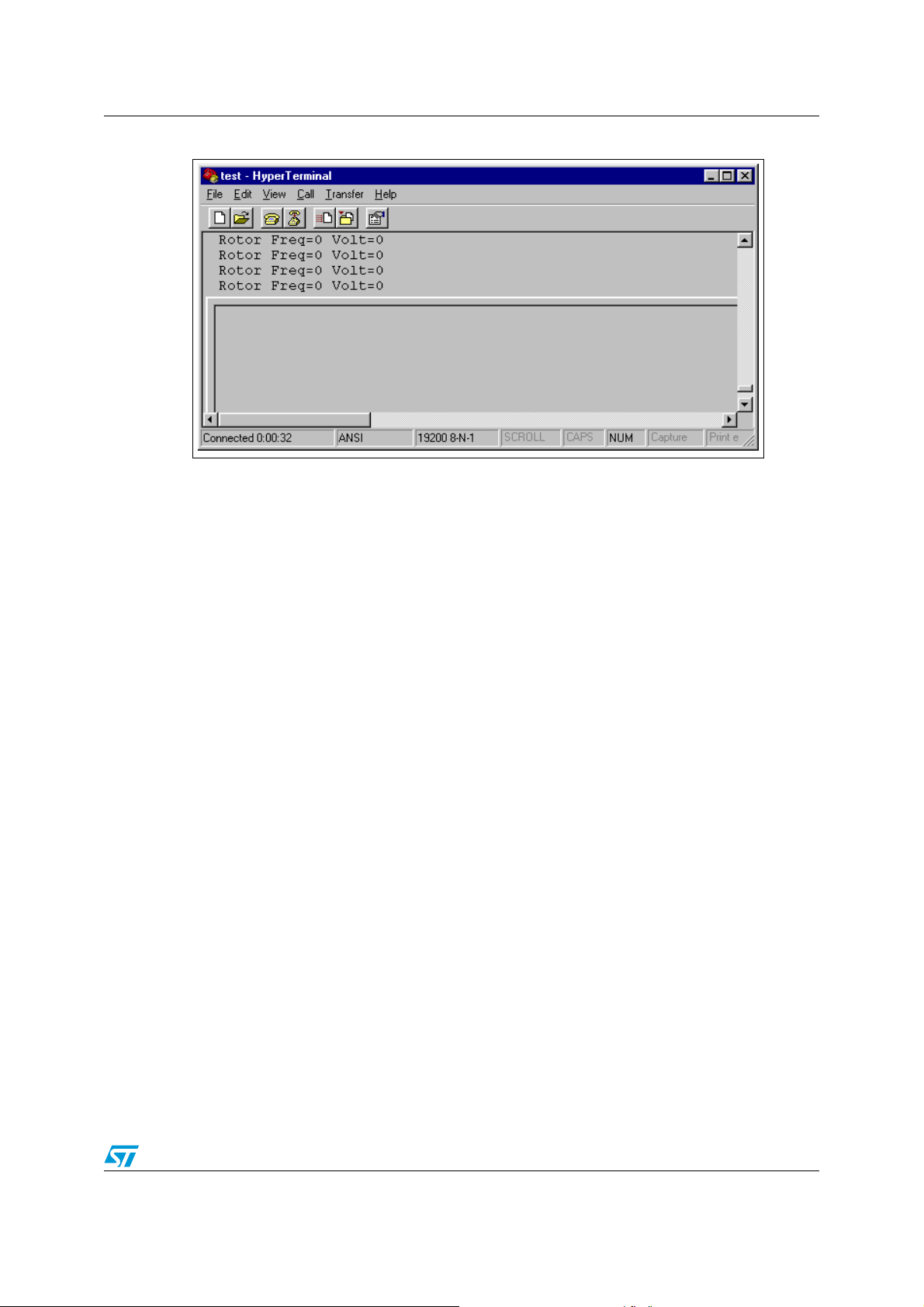
AN1904 Library functions per software module
Figure 36. HyperTerminal
4.7.2 Implementation
Here are the serial communication characteristics:
● 19200 baud,
● 8-bit data,
● 1 stop bit,
● No parity,
● No communication protocol,
● Transmission only.
Three-lines only are needed for such asynchronous transmission; the pin number
corresponds to a standard DB9 female connector:
● Tx and Rx (pin 2 and 3 on a standard null modem cable),
● Ground (pin 5 of DB9 female connector).
Since the ST7 is sending the data with its own timebase, the transmission period is known.
For instance, speed regulator reaction time in closed loop mode can be easily evaluated by
importing on a spread sheet editor the data files coming from Hyperterminal, assuming an
interval between data frames of 100ms for instance to have a consistent time axis
representation.
Refer to Section 5.3 on page 83 for examples of SCI use in the software library.
4.7.3 Changes vs ST7 library
■ The current set of files (sci.c, sci.h) have been customized for the ST7MC hardware
registers, and the ST7 library set-up files have been removed (sci_hr.c, sci_hr.h,
st7lib_config.h). Consequently this module is not compatible as it is with products other
than ST7MC.
■ Three routines have been added to convert variables in character strings:
void PrintUnsignedInt(unsigned int x);
77/102
Page 78

Library functions per software module AN1904
void PrintUnsignedChar(unsigned char x);
void PrintSignedChar(signed char x);
These functions call the SCI_PutString subroutine to send the character string after the
conversion. In their current form, they are not compatible with interrupt driven transmission.
■ Another routine has been added to concatenate an unsigned integer in a character string,
for both polling and interrupt driven transmission:
void strcatu16(const unsigned char *PtrtoString, unsigned int x);
4.7.4 Customization
Please refer to the ST7 library documentation for help on functions, communication set-up
and implementation examples.
Transmission / reception method
Two methods are available: polling or interrupt driven. The first method has been chosen for
the current library: once a SCI function is called, it is only exited upon completion of the
transmission. This must be remembered when a watchdog is used. It can be changed in the
config.h file to have access to the right functions prototypes:
#define SCI_POLLING_TX /*Polling mode transmission*/
//#define SCI_ITDRV_WITHOUTBUF_TX /*Interrupt driven without buffer transmission
mode*/
#define SCI_POLLING_RX /*polling mode reception*/
//#define SCI_ITDRV_WITHOUTBUF_RX /*Interrupt driven without buffer reception mode*/
Baud rate
The communication baud rate can be adjusted from 38400 to 1200 bauds or less, keeping in
mind that the length of the transmission will increase accordingly.
4.7.5 Important notice for hardware implementation
There must be a galvanic isolation between the ST7MC and the PC serial port if there is
none implemented between the MCU and the power inverter. This will lower the risk of user
injury and damage to the computer’s serial port.
This is achieved by adding optical-isolators between the MCU and the level converter (RS
232 transceiver) directly connected to the serial bus.
4.8 Nested interrupt controller
The demo program provided to start working with the software library benefits from the ST7
nested interrupts controller. Below is a table summarizing the priorities of the available
interrupts.
It must be noted that any missed Update interrupt (MTC_U_CL_SO_IT) will lead to sine
wave distortion, which in turn may be a source of reactive current in the inverter. This is the
reason why the sine wave generation dedicated interrupt is and must be maintained
highest priority level.
at the
78/102
Page 79

AN1904 Library functions per software module
The only case where these interrupts may be delayed is upon emergency stop event, when
PWM outputs are not active any more.
Table 3. ST7MC Software library interrupt priorities
Priority Interrupt Name Purpose
Top Level
MCES_SE_IT Emergency Stop Event management
MTC_U_CL_SO_IT Sine wave generation
MTC_C_D_IT Tachogenerator signal capture
Medium/High
MTC_R_Z_IT Automatic MTIM prescaler update
ART_Interrupt 1 ms timebase
Medium/Low All others Not used
79/102
Page 80

Running the demo programs AN1904
5 Running the demo programs
Two demo programs are included in the main.c routine to demonstrate either the Open Loop
or Closed Loop operations.
The choice is made with conditional compilation keys in config.h file (see Section 3.2 on
page 12). These programs are just intended to provide examples on how to use the software
library functions. After the MCU initialization phase, a simple state machine handles the
motor control tasks in the main loop, as well as a basic monitoring of the power stage and, if
needed, transmission of data on the serial interface (see Figure 37).
Figure 37. Demo program flow chart
RESET
RESET
M CU peripherals initialization
M CU peripherals initialization
E n a b le in te rru p ts
E n a b le in te rru p ts
State = ID LE
State = ID LE
Toggle LEDs
Toggle LEDs
D o M otor C ontrol State M achine
D o M otor C ontrol State M achine
M o n ito r P o w e r S ta ge
M o n ito r P o w e r S ta ge
Send data on RS232 (optional)
Send data on RS232 (optional)
The state machine described on Figure 38 does not differentiate open from closed loop
control, at the exception of the starting phase initialization (when state = IDLE).
The power stage is monitored using the ADC and the MCES input to verify the following
parameters:
● Heatsink over-temperature (on ADC’s channel AIN0),
● DC bus over-voltage (on ADC’s channel AIN1),
● Over-current protection (low state on MCES input).
Any of these three conditions will cause the PWM to be stopped and the state machine to go
in the FAULT trap state (meaning that a hardware reset is needed to re-start the motor).
The following sections detail the particularities of these controls, located in two functions:
void DoMotorControl(void)
SystStatus_t StartMotor(void)
80/102
Page 81

AN1904 Running the demo programs
Figure 38. Main loop state diagram
Brake duration elapsed
1s time elapsed
Idle
5.1 Open loop
This program converts the RV1 and RV2 trimmer readings (channels AIN13 and AIN12) into
stator frequency settings (10.0 to 265.0 Hz) and voltage (0 to 255 modulation index)
respectively. See flowchart on A.1.11 on page 99 for details.
Wait
Button pushed
Brake
Brake torque=0
HW Fault
Start on-going
Brake torque>0
Stop
HW
Fault
Fault
Start fails
HW or
start-up
fault
Start
HW Fault
Start OK
Button pushed
Run
These parameters are taken into account at start-up, then modified in real time every time
the main loop is executed.
It must be noted that the voltage on the motor is limited by the V/f curve defined by default;
you have the choice to:
● scan the whole voltage domain below the V/f curve by modifying both RV2 and RV1, to
characterize the motor for instance,
● set RV2 to its maximum value, and then run the motor following the V/f curve, just
modifying the speed (stator frequency) with RV1.
Since no tests are performed on the stator frequency, RV1 trimmer should be set at a low
value during the start-up to limit the inrush current in the motor. Then, it must be modified
smoothly to avoid:
● entering the unstable working domain of the AC motor, which will cause it to stop,
● entering the generator domain if the slip is negative (stator frequency below rotor
frequency).
However, a variation rate limitation is implemented, to limit the frequency variation to +/- 5Hz
per second and the voltage variation to +/- 50 per second. This slew rate is set-up in the
ACM_SoftStartOL function, using ART_Set_TimeInMs(SLEW_LIMIT). The
SLEW_LIMIT constant is defined to 20ms at the beginning of the acmotor.c file (which gives
1s/20ms=50).
Note: By default, a tachogenerator is available in the system (the function MTC_GetSlip is used to
avoid if possible any operation with negative slip). This is convenient for demo purposes with
the SELNI motor and during incremental system build (see Section 6.2). For an application
81/102
Page 82

Running the demo programs AN1904
without any sensors available, all functions related to speed feedback processing (at the
sole exception of the capture interrupt service routine) will be automatically be removed by
the linker if not used.
5.2 Closed loop
In this mode, the RV1 trimmer is read on channel AIN13 to set the target rotational
frequency. Optionally, the RV2 and RV3 trimmers can be used to set the Kp and Ki
parameters on the fly. PI regulator implementation and tuning on page 62.
The speed regulation is achieved using a closed loop slip control. Actually, only the voltage
is controlled by the regulator to maintain a constant slip during the motor operation: see
Figure 31 on page 68. This regulation loop is executed in the DoMotorControl function
every 10ms, as defined by the
63).
It must be noted that the rotor frequency is measured every time this function is called,
independently from the regulation sampling time; if the returned rotor frequency is zero, the
motor is considered to be stalled and the state machine will enter the FAULT state, requiring
a hardware reset to be exited (see state diagram on Figure 38. on page 81).
In parallel with the voltage regulation, the stator frequency is modified in open loop, as
represented on the flow chart on Figure 39
SAMPLING_TIME parameter set in ACMparam.h (see l on page
Figure 39. Stator frequency update
Current Stator freq
OptSlip = f(StatorFreq)
Sup
CurrentSlip <
Accel Limit
Stator freq++
No
Yes
End
End
No
Target Rotor freq
CurrentSlip >
Decel Limit
Yes
Stator freq --
New Stator freq
Inf
Update Stator freq
Compare
with
Current
Stator Freq
=
End
During closed loop operations, the slip frequency is continuously monitored to be
maintained between two limits, to be entered with 0.1Hz unit.
● Maximum Slip (acceleration limit)
This threshold is here to avoid the motor entering its unstable working domain in case of
excessive torque request: this will cause it to stall. If this limit is exceeded
(ACCEL_SLIP_LIMIT define, set in Mainparam.h header file), the stator frequency will not
being increased any further.
82/102
Page 83

AN1904 Running the demo programs
This may occur in the following cases:
● the desired acceleration rate exceeds the gain / bandwidth capabilities of the regulation
algorithm and/or motor torque capabilities,
● the resistive torque exceeds maximum motor ratings.
It is worth noting that this feature allows a torque control mechanism during speed ramp-up,
assuming that torque is a function of the slip, in the first order: see Figure 40
Figure 40. Controlled slip during acceleration provides torque control
Torque
● Minimum slip (deceleration limit)
F
1
Constant Slip
F2 > F
> F
F
2
1
1
This limit is here to avoid re-generative currents that are produced when the stator
frequency goes below the rotor rotational frequency, during a deceleration for instance.
If this limit is exceeded (DECEL_SLIP_LIMIT define, set in Mainparam.h header file), the
stator frequency will not be decreased any further.
5.3 Using the serial communication interface
The serial communication interface is not enabled by default. To use it, one must edit a
define in the config.h file (#define ENABLE_RS232, see Section 3.2 on page 12). Once
this is done, the following parameters are transmitted continuously on the Tx pin, depending
on the mode:
● Open Loop mode
The stator frequency is sent, with 0.1Hz unit (Freq=125 corresponds to 12.5Hz), as well
as the voltage modulation index (8-bit value, Volt=255 corresponds to full voltage). This
is convenient to know exactly the value set with the trimmers.
● Closed Loop mode
The speed command is send, with 0.1Hz unit (S= 568 means a speed target of 56.8Hz
rotational frequency), to get the value read on the trimmer which set the speed. If the
PI_PARAM_TUNING key is defined in the config.h file, the K
also transmitted.
Constant
motor torque
Speed
and Kp parameters are
i
Note: The interval between two frames in not constant: data transmission is restarted during the
main loop if the previous frame is completed, giving some jitter equal to the main loop
duration.
83/102
Page 84

Running the demo programs AN1904
5.4 Mainparam.h file description
Mainparam.h contains some application/demo specific features, subject to change during
run-time (depending on the target speed for instance).
5.4.1 Start-up parameters
In this section, parameters for both closed and open loop demos are grouped together. See
Section on page 68 for details.
#define START_VOLTAGE ((u8)30); //Open Loop only
#define START_FREQ ((u16)150)// Open & Closed Loop
#define MIN_START_FREQ ((u16)100) // Closed Loop only, resolution:
0.1Hz
5.4.2 Brake parameters
Two out of the four brake parameters are defined in this section: the duty cycle (defining the
braking torque) and the duration. They may be modified in the application depending on the
current stator frequency and conditions (for emergency brake or normal deceleration).
When adjusting these parameters, attention must be paid to thermal and over-current
limitations if the braking phase is too long and/or with too high current.
#define BRAKE_DUTY_CYCLE ((u16)64)
#define BRAKE_DURATION ((u16)3000)
The remaining parameters are discussed in the Brake on page 45.
5.4.3 Closed-loop slip control
These values are necessary during speed variations (see Section 5.2) and may vary during
run-time to adjust for instance the maximum torque during ramp-up.
#define ACCEL_SLIP_LIMIT ((u16)100)
#define DECEL_SLIP_LIMIT ((u16)10)
84/102
Page 85

AN1904 Designing your application with the library
6 Designing your application with the library
6.1 Library maintenance
Once the tools and demo programs have been successfully run, you will have to integrate
this library in your own design. Some modules will be used as they are, others will have to
be completed and some will have to be created.
Before starting this process, two important points must be considered to benefit from:
● updates (various improvements, new modules or modulation methods, etc.)
● STMicroelectronics assistance and support on tools and/or application software (even
though source codes and flowcharts are provided to make customization and in depth
library understanding as easy and clear as possible).
You should follow the recommendations listed below in order to benefit from the latest library
upgrades (by simply replacing existing modules with the new ones without any source level
modifications):
● Try not to modify mtc.c and acmotor.c modules. These modules can be almost
completely customized in the MTCparam.h and ACMparam.h header files (see Tab l e 4
for other modules). If you edit mtc.c and acmotor.c , carefully trace all modifications in
order to ease STMicroelectronics’ support and follow future upgrades of the library.
● Try to maintain existing function interfaces; create new functions if the existing ones are
not convenient. The linker will remove unused functions at link time.
● A modular approach should be used as often as possible.
● Use functions such as ACM_SustainSpeed as an example, and implement modified
versions outside source modules if they do not fit your application.
The following matrix (Ta bl e 4 ) describes the module classification for customization:
● Class A: Code inside the module can be removed and modified
● Class B: Code can be added to a module. Existing functions, define statements and
constants should nevertheless be maintained for upward compatibility,
● Class C: Code must not be modified (Motor control software library core modules,
header files maintained by ST, such as ST7FMC2N6.h file).
Table 4. Module classification (cf. above text for explanations on A, B, C classes)
Name
Module
Ax
B xxxxx xxxxxx
Cxx x
mtc.c & .h
acmotor.c & .h
sci.c & .h
adc.c & .h
ST7_Misc.c
pwmart.c & .h
ports.c & .h
main.c
MTCparam.h
ACMparam.h
Mainparam.h
config.h
lib.h
mtc_bits.h
ST7FMC2N6.h
85/102
Page 86

Designing your application with the library AN1904
6.2 Incremental system build
The methodology below should be considered only as a set of guidelines which can be
followed when developing the final application (hardware and firmware), to minimize the
development time and to progressively gain confidence in both:
● the newly implemented software modules
● the various part of a hardware motor drive design.
All the steps here-below described can be managed either with trimmers/push-buttons or
with the help of the ST7MC Control panel.
This methodology does not supersede standard software development processes or
hardware qualification procedures.
6.2.1 Preliminary notice on debugging tools
Low voltage applications (below 30V)
For these voltage levels, the real-time emulator can be connected in the application, taking
care to connect the protective boards provided with the MDT50 emulator (refer to the
emulator datasheet for details). It offers trace and advanced breakpoints capabilities, as well
as the possibility to automatically disable the PWM outputs on a breakpoint to avoid any DC
current injection in the motor (see Figure 41).
This emulator is delivered with a set of three boards to protect some of the motor control
dedicated I/Os from voltages greater than 5V. It is highly recommended to have them
connected during the development. A neutral board is also provided in case the protection
network’s impedance (1K series resistor plus 5V3 zener diode) is an issue for the
application. Refer to ST7MDT50-EMU3 Probe user guide section 3.1 for details.
An In-Circuit Debugging tool can also be directly connected, as long as an ICC connector is
available on the application.
Caution: When using ICD, during a breakpoint, the clock circuitry is not disabled: a permanent DC
current may flow in the motor is the PWM outputs are enabled. It is thus recommended to
use a power supply with fast current limitation capabilities or if possible to disable the PWM
outputs (by inserting MTC_DisableMCOutputs function) before the breakpoint.
Figure 41. Configuring the Motor Controller clock state on breakpoint with MDT50
86/102
Page 87

AN1904 Designing your application with the library
Medium-high voltage application (above 30V)
Here, use of the real-time emulator is not recommended, even if protective boards are
inserted.
Warning: In case of high voltage applications connected on the mains,
the application ground may be at a dangerous voltage; as
would the MDT50 emulator (the protective boards do not
provide galvanic isolation).
For voltages above 30V, it is highly recommended to use only programmed devices. ICD
debugging can be used in conjunction with an ICC isolation board, as the one provided with
the ST7MC-KIT/BLDC starter kit, but the limitations mentioned in Section nevertheless
applies, and are even emphasized by the high voltage levels.
Good practice for real-time applications debugging is to use “diagnostic tools” such as:
● RS232 communication (refer to Section 5.3 on page 83), which can be easily isolated,
● Stand alone DAC (serial SPI-based model for instance) to be able to monitor signals on
an oscilloscope,
● debug outputs of the ST7MC itself (MCDEM and MCZEM pins), to monitor the U and C
events (refer to datasheet for details).
Refer to AN438 (Safety Precautions for Development Tool Triac + Microcontroller) for further
details when working on the mains.
6.2.2 Build step1: open loop, low voltage, no motor connected
In these conditions, some functions not related to motor control can be tested and debugged
(such as serial communication, some analog measurements,...).
Supplying only the MCU and the gate drivers (if any), one can verify that the PWM signals
are present on the MCOx outputs, on the MOSFET/IGBT gates, with no voltage applied on
the inverter. This can be tested either with the standalone demo program, using push-button
and trimmers to start the motor control tasks, or using the ST7MC control Panel.
If the signals are correct, a low voltage can be applied on the inverter power stage (<30V) to
verify the signal on the central point of the half-bridges and the expected shape of the motor
current by low-pass filtering the PWM modulated signals. Sine wave voltage can be
displayed on an oscilloscope using a RC network (10K / 22nF for instance for 12kHz PWM
frequency).
It is recommended to restart from this first step every time a major modification is done on
either the hardware or the software part of a design.
87/102
Page 88

Designing your application with the library AN1904
6.2.3 Build step2: open loop, rated voltage/power, motor connected
With the trimmers or the ST7MC control Panel, scan the whole motor (and inverter) working
domain, at increasing voltage levels (or increasing current levels for low voltage
applications):
● verify that the inverter is running fine and gain confidence in the power stage,
● verify that the electronics are able to deliver the rated power (this power level is
independent from any speed regulation and will not be increased when implementing
the closed loop control),
● verify that the motor is able to deliver the maximum expected torque in the application.
Good practice for applications connected to the mains is to verify these parameters taking
into account the voltage variations (for instance 230V
+15/-10% imposes a 207-264V
rms
rms
operating range for the drive).
The DC braking functionality can also be tested and the braking torque set-up during this
phase.
Caution: During this phase, nothing prevents the stator frequency going below the rotor frequency. It
is therefore necessary to pay attention to avoid reactive current generation when modifying
the stator frequency (MTC_UpdateSine on page 31 for details).
6.2.4 Build step3: open loop, rated power, motor connected with speed feedback
If the motor has a speed sensor, one can verify that the speed feedback processing is
correctly set-up (returned rotor frequency should be close to stator frequency). This must be
done in the worst case conditions (from EMI point of view):
● maximum voltage or current (for instance mains supply +15%)
● at null voltage modulation index (variable voltage = 0): this will lead to synchronous
50% duty cycle PWM signals on each of the three half-bridges and therefore
synchronous dV/dt transients, resulting in very high conducted EMIs when
charging/discharging the three motor’s stray capacitance.
This will avoid doubts on the speed measurement reliability during the further development
steps.
At that time, it is also convenient to evaluate the quality of speed feedback in very stable
speed conditions (such as no-load or on a dynamo meter): any variation on the speed
sensor feedback which may appear will either reflect the sensor’s mechanical dissymmetry
or add errors induced by electrical noise to the tachogenerator signal. These effects will help
in knowing if speed averaging is necessary, and on how much information the rolling
average must be done.
The minimum reliable speed feedback can also be measured during this build step (at low
speed, tacho generator signal is very low and may not be properly amplified by the
conditioning stage.
Finally, on a motor bench, with a static brake and a dynamo meter, the optimum slip versus
speed characteristic can be easily characterized if needed.
6.2.5 Build step4: closed loop operation
Start the motor with the PI controller disabled (Kp=Ki=0) and then close the loop by starting
to tune the PI algorithm, following the procedure described in Section on page 62.
88/102
Page 89

AN1904 Designing your application with the library
From this point, it is then more or less mandatory to work on the final application’s load.
Having these 4 steps completed successfully will give full confidence on the motor control
modules when integrating the motor control library within the complete application.
6.3 Motor control related CPU load in the application
6.3.1 Estimation
The CPU load consumption induced by the motor control comes from three tasks mainly,
listed below.
● Sine wave generation
This is the main source of work for the CPU and it is done in interrupts
(MTC_U_CL_SO_IT) at a fixed rate: the related value is thus constant whatever the
sine wave frequency or voltage; calculation is discussed in Section on page 42.
● Speed feedback processing
This is also done in interrupt (MTC_C_D_IT), at a rate proportional to the motor speed.
For instance, taking the SELNI motor (with 8-poles tachogenerator) running at
20000RPM (highest speed), this gives:
– 20000RPM / 60 = 333.3Hz rotational frequency
– 333.3Hz x 8 = 2666.6Hz tacho frequency and 375µs tacho period
Thus the tacho related CPU load is 22µs/375µs = 5.8% (i.e. interrupt duration/tacho period).
● PI regulator
This term includes the ACM_SlipRegulation and the MTC_UpdateSine functions
(respectively 2.7ms and 630µs) and takes into account the 20% of CPU spent for sine
generation: this should be remembered when calculating the total load.
This contribution is inversely proportional to the sampling time of the PI regulator.
For instance, if T
sampling
= 20ms, this will lead to:
(2.7+0.63) / 20 =13.5%.
● Total CPU load
Here below is an example for a SELNI motor running at 10000RPM:
Total CPU load = 13.5% (PI) + (1-13.5%) x 21.3% (sine) + 2.9% (tacho) = 35%.
Note: For open loop applications, CPU load is constant and sine wave generation is the only
parameter to be taken into account.
6.3.2 Adjustment guidelines
Besides adjusting the CPU load related to the sine wave generation, one can adjust several
parameters to speed things up if this is necessary.
● the PI regulator can be re-written using 16-bit arithmetic rather than 32-bit.
● the T
● the conversion from rotor period to rotor frequency takes more than 500µs. One could
sampling time can be increased (at high speed particularly if inertia is high).
s
use the period for speed measurement and regulation, instead of rotor frequency. This
would save 16-bit division (but has the disadvantage of imposing management of non-
linear speed characteristics in 1/x form).
89/102
Page 90

Appendix AN1904
Appendix A Appendix
A.1 Flowcharts
A.1.1 MTC_U_CL_SO_IT interrupt routine
Is a frequency
update required?
No
Scale according to voltage command
Sample from
sine’s positive
half-period?
Yes
Add 50% duty cycle offset to the MSB
Yes
Get new frequency command coming
Integrate frequency into phase to
get pointer on sine Look-up table
Get sample from table
No
Shift right result to match the 9 or
10-bit range for compare register
Load compare register’s LSB
Load compare register’s MSB
from MTC_UpdateSine
Complement
result
Add 120° for Phase B pointer
Redo PWM calculation for Phase B
Add 120° for Phase C pointer
Redo PWM calculation for Phase C
IRET
90/102
Page 91

AN1904 Appendix
A.1.2 MTC_C_D_IT interrupt routine
Initialize rolling
average
No
Store MZREG and MZPRV
registers in the FIFO stack
No
MTIM timer
prescaler ratio
change?
Stack filled?
No
Incremented
Yes
Decremented
Store MPRSR + 1
Yes
Store in a temporary buffer the
last values of MZREG, MZPRV
and MPRSR registers
Fill the whole FIFO stack with
these 3 values
Reset the FIFO pointer
Reset the rolling average
initialization flag
Increment
pointer
Reset ratio update
flags (set in R interrupt)
Reset pointer
Reset C flag
IRET
91/102
Page 92

Appendix AN1904
A.1.3 MTC_GetRotorFreq function
No
Is rolling average
Get Last tacho period
Is tacho period too small
(spurious event) or is a
(spurious event) or is a
TimeOut detected?
No
Compute rotor frequency
Compute rotor frequency
as 1/T
tacho
Returns the rotor frequency with 0.1Hz unit
Yes
enabled?
Get averaged tacho period
Yes
Return a null Frequency
92/102
Page 93
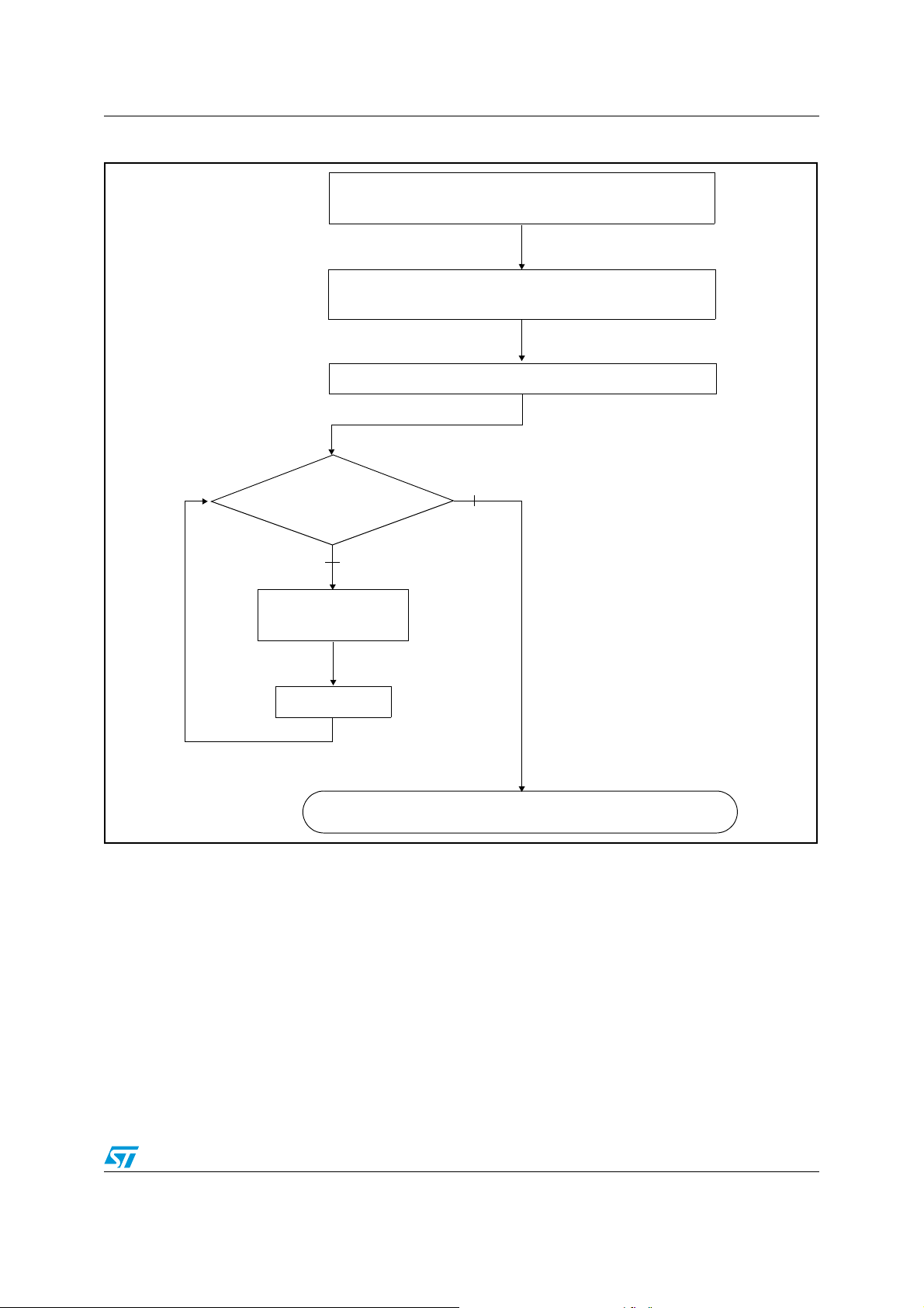
AN1904 Appendix
A.1.4 GetLastTachoPeriod function
Store current FIFO pointer (needed if a new
tacho capture occurs during computation)
Store 16-bit value of tacho period (variable
time unit)
Get ST[3:0] bits out of MPRSR values stored
ST[3:0] equal
to zero?
No
Multiply by two
the tacho period
ST[3:0] - 1
Yes
Return tacho period with T
mtc
unit
93/102
Page 94
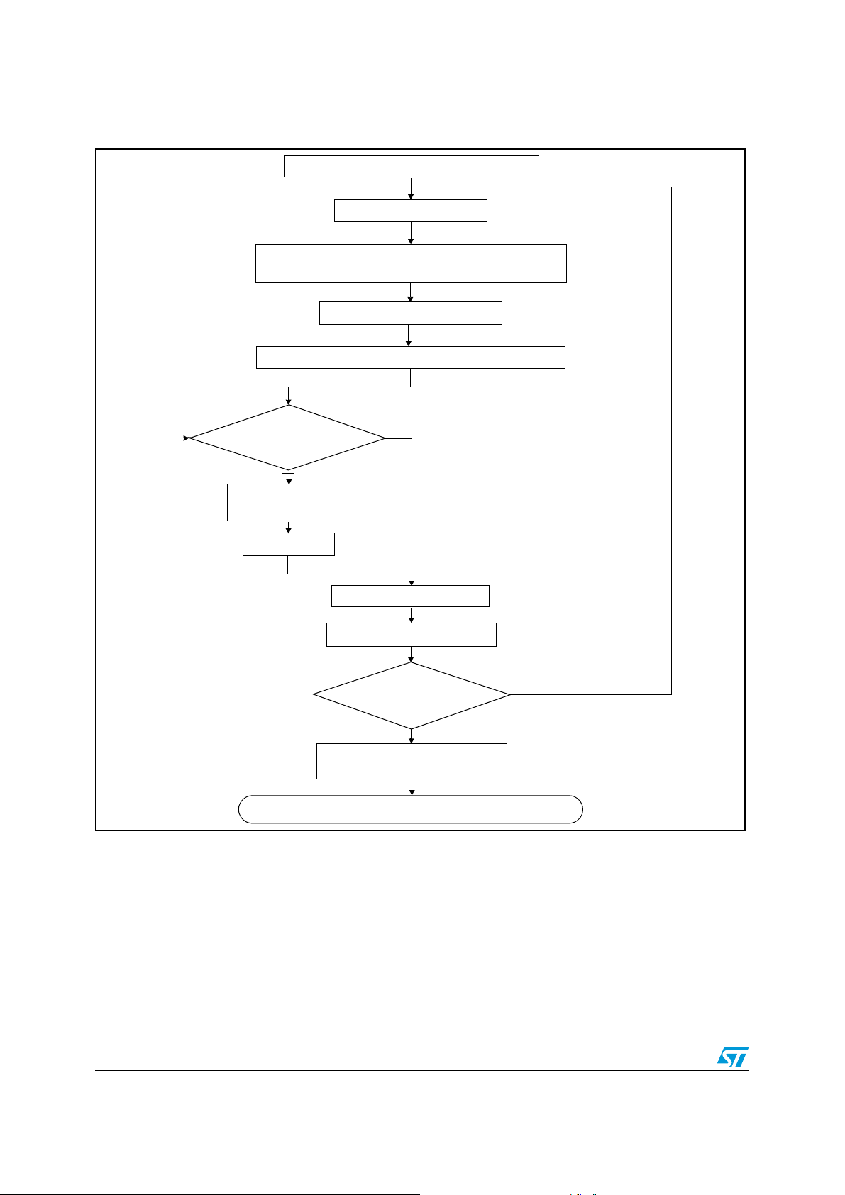
Appendix AN1904
A.1.5 GetAvrgTachoPeriod function
Store base address of FIFO stack
Disable C interrupts
Store 16-bit value of tacho period (variable
time unit)
Re-enable C interrupts
Get ST[3:0] bits out of MPRSR values stored
ST[3:0] equal
to zero?
No
Multiply by two
the tacho period
ST[3:0] - 1
Return tacho period with T
Yes
Accumulate period
Increment FIFO pointer
End of FIFO
stack?
Yes
Compute average and
round to the upper value
mtc
No
unit
94/102
Page 95
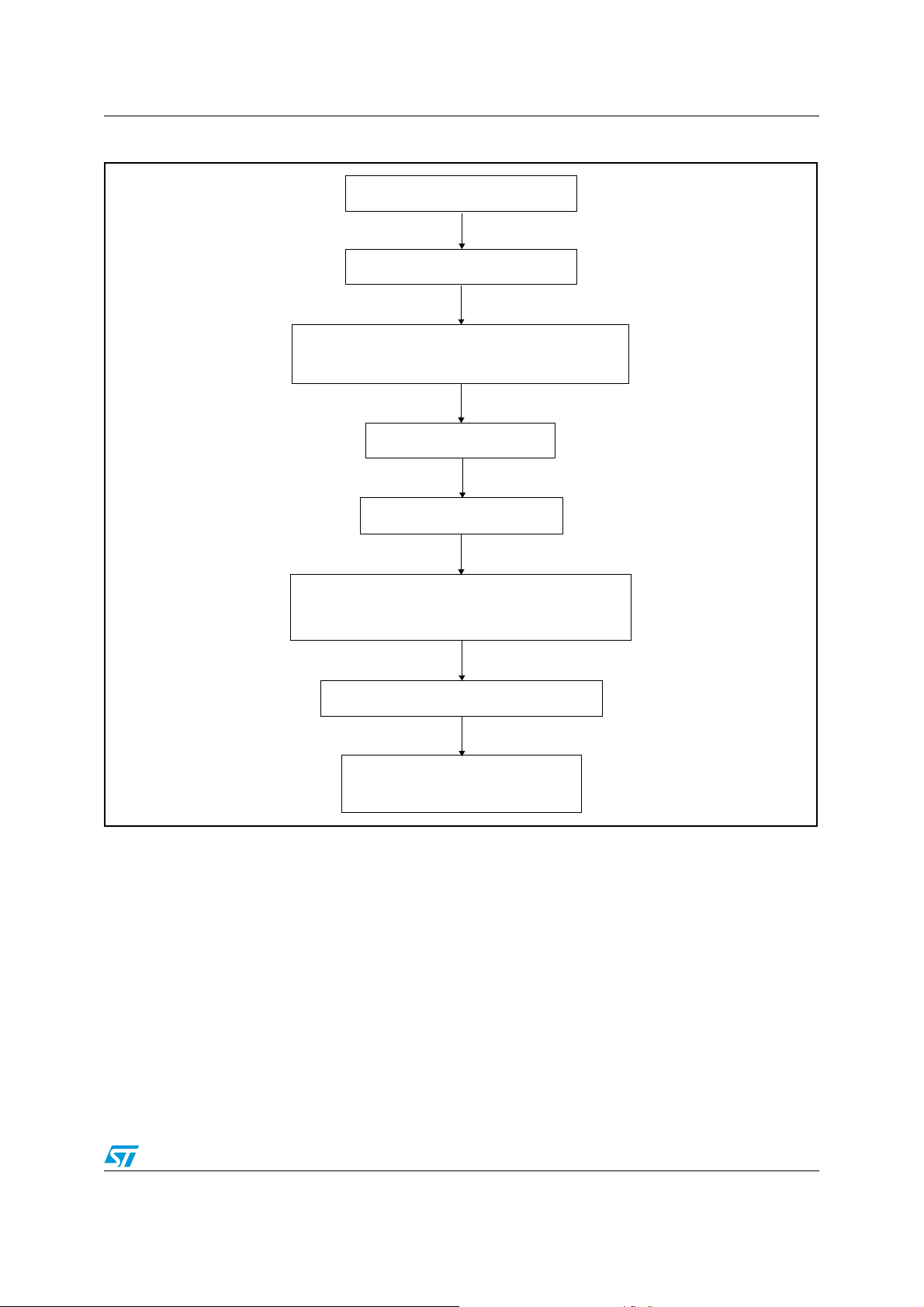
AN1904 Appendix
A.1.6 MTC_StartBraking function
Reset brake related flags
Set motor voltage to zero
Force PWM Update event to be sure
that PWM registers are updated
Disable U interrupts
Disable PWM outputs
Initialize flags for brake state machine:
State = BRAKE_WAIT_DEMAG
Program Demagnetization time
Set target brake intensity
(PWM duty cycle)
95/102
Page 96

Appendix AN1904
A.1.7 MTC_Brake function state diagram
State = BRAKE_WAIT_DEMAG
Demagnetization time elapsed
Program the current increase rate
Set all the low side switches ON
Current increase
timebase elapsed
Increase PWM duty
cycle on Phase U
A.1.8 MTC_StopBraking function
Reset brake related flags
Set all duty cycles to zero
Disable PWM outputs
Re-enable U interrupts for
sine wave generation
State = BRAKE_SET_UP
PWM duty cycle =
target brake duty cycle
State = BRAKE
96/102
Page 97

AN1904 Appendix
A.1.9 ACM_InitSoftStart function
Initialize tacho measurement
Set Voltage to zero
Enable PWM outputs
Compute Soft start timebase
(SSTB) as TimeOut/Max
voltage from V/F curve
Yes
SSTB = 0?
No
SSTB = 1
Program Voltage increase rate
timebase with SSTB value
Program Time Out for the
while Soft Start sequence
97/102
Page 98

Appendix AN1904
A.1.10 ACM_SoftStart function
Get current Stator frequency
Get current voltage applied on
motor
Compute max voltage from V/f
characteristic
Is Min Rotor frequency
>= Stator frequency?
No
Is Min Rotor
frequency reached?
No
Is Soft start time
out elapsed?
No
Is SSTB time
base elapsed?
Yes
Is Voltage >
Voltage Max?
Yes (Error)
Yes
Returns START_OK
Yes
Returns START_FAIL
No
Yes
No
Increase Voltage
98/102
Returns START_ONGOING
Page 99

AN1904 Appendix
A.1.11 Open Loop motor control demo program
Read Voltage command from
Trimmer RV2
Read frequency command
from Trimmer RV1
Get current voltage
Get current Stator Frequency
Get current Slip Frequency
Volt Cmd =
Vmax
Voltage
Command =
Current voltage
-1
No
frequency
Yes
Frequency
Command =
Frequency - 1
Risk of reactive current
Slip
>0?
Current
Yes
inf
Is SLEW_LIMIT
Timebase elapsed?
Yes
Is Voltage
Command > Vmax?
Voltage Command
vs Current
Voltage?
same
inf
Refresh Sine parameters with
new Command values
No
Frequency Command
vs Current
Frequency?
same
No
sup
Command =
Current coltage
Exit
Voltage
+1
sup
Frequency
Command =
Current
Frequency + 1
99/102
Page 100

Appendix AN1904
A.2 Selni motor characteristics
MANUFACTURER:
SELNI - NEVERS - FRANCE
MOTOR:
AHV 2-42-
MAIN CHARACTERISTICS:
MOTOR for WASHING MACHINES
Phase to phase voltage:0 to 190 V or 0 to 250V
Frequency (F): 0 to 340 Hz
Insulation Class: F
Geometry: drawing 10102
Speed ratio (belt): 10 to 16
Speed: 0 to 20000 RPM
Special characteristics:
Stack Thickness: 42 mm
Stator ref.: drawing 10230
Stator lamination ref.: 21760 (24 slots)
Winding: 2 poles, embedded, real poles
Without thermal protector
Rotor ref.: drawing 10207T01
Rotor lamination ref.: 27525 (28 slots)
Tacho Generator: Electromagnet T 31 (2*8 poles)
Optimum slip: From 3 Hz at low Frequencies to 8 HZ at high
Frequencies
Maximum Torque: 2 to 3 Nm at low speed
Maximal slip: For F ≤ 5 Hz
R= 3,5 Ω ± 5% ph to ph. at 23°C
⇒ 5 Hz
13 Hz
⇒ 5 Hz 25 Hz ⇒16 Hz
200 Hz
⇒28 Hz 340 Hz ⇒35 Hz
100/102
 Loading...