

Page 1

AN1828
APPLICATION NOTE
PIR (PASSIVE INFRARED) DETECTOR USING
ST7FLITE05/09/SUPERLITE
INTRODUCTION
The document explains how to design a low cost PIR detector (human motion detector) using
the ST7FLITE05(09) microcontroller family. The technique used is software Sigma-D elta A/D
Convers ion, suit able for de tectin g low-fre quency sensor s ignals. Refer to A N1827 f or a detailed explanation of the Sigma-Delta technique. The same concept can also be used for other
sensor applications such as:
– Security Systems.
– Automatic lighting Systems
– Automatic Door Openers
Rev. 1.0
AN1828/0304 1/17
1ddd
Page 2
PIR (PASSIVE INFRARED) DETECTOR USING ST7FLITE05/09/SUPERLITE
1 SENSOR OVERVI EW
The human body radiates infrared waves with wavelengths of 8 to 12 micrometers. Any movement by a person leads to a change in the amount of infrared energy which a sensor can detect within its range. The PIR sensor reacts to this change in infrared energy and provides a
low-frequency, small amplitude signal. This signal can be amplified and decoded using a
ST7Lite05 microcontroller (as explained in Section 1.2).
1.1 INFRARED FOCUSING BY FRESNEL LENS
The sensor can sense the change in the amount of infrared energy within small distances, approximately up to 10 inches . For detecting m ovements at longer distance, infr ared radiation
has to be focused. This focusing is done by a Fresnel lens. A Fresnel lens divides the whole
area into different zones. Any movement between zones leads to a change in the IR (infrared)
energy received by the sensor. There are different types of Fresnel lenses depending on the
range (distance) and coverage angle. For example, volumetric lenses and curtain lenses etc.
1.2 PIR DETECTOR USING ST7FLITE05 MICROCONTROLLER
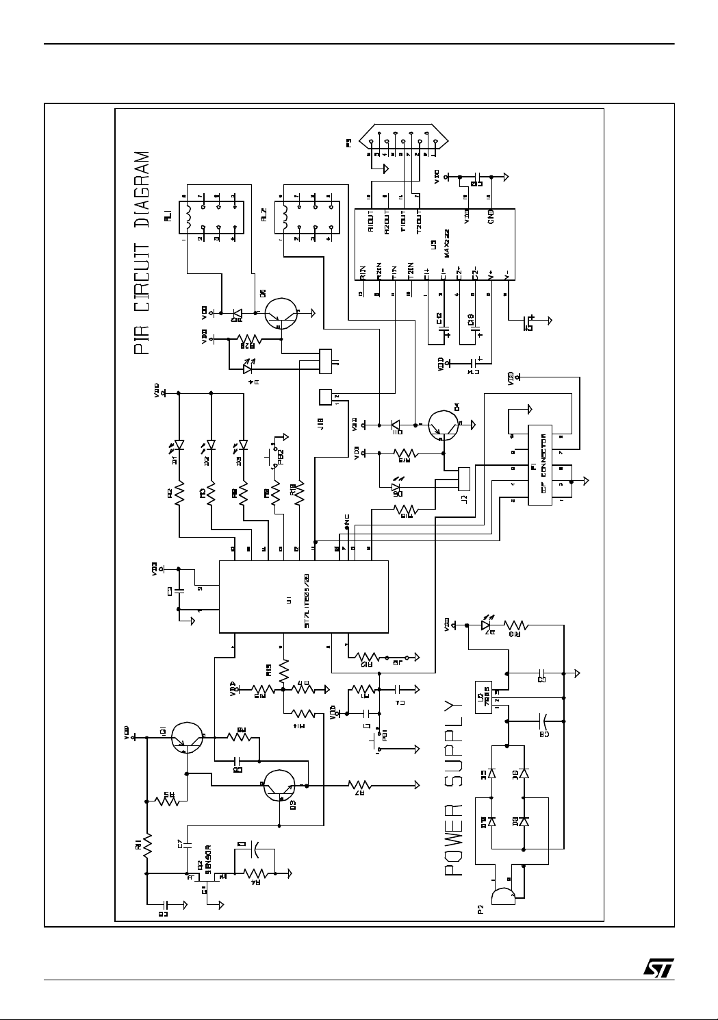
A PIR detector can be made easily with ST7FLITE05 using the circuit shown in Figure 2. The
sensor interfacing circuit (shown on the left side of the microcontroller in Figure 2) can be di-
vided into the following modules:
1.Transistor circuit used as an amplifier.
2.Transistor biasing controlled through the microcontroller.
3. Software-controlled transistor output.
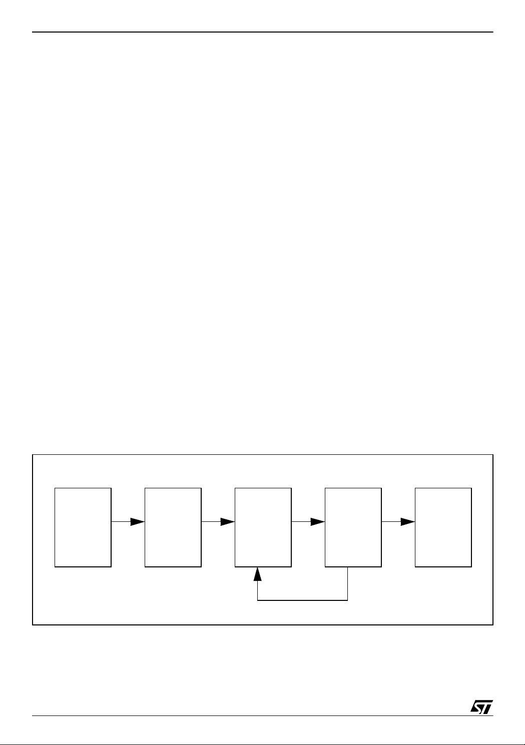
Figure 1. Block Diagram
PIR sensor RC
Integrator
Transistor
Amplifier
ST7 Micro-
controller
Alarm
Biasing Signal
2/17
2
Page 3

PIR (PASSIVE INFRARED) DETECTOR USING ST7FLITE05/09/SUPERLITE
1.3 SENSOR CIRCUIT DESCRIPTION
Transistor Q3 is biased in the active region and amplifies the signal from the PIR sensor. The
microcontroller provides a biasing signal, which is connected to the biasing network on the
transistor. This biasing sign al is integrated through a capacitor (C7) and resistor (R14). The
bias signal at 0 level (LOW) for a long time (greater than the discharging time of the capac itor)
puts the transistor into the cut-off region, making it OFF. The HIGH from the microcontroller for
a long ti me (g reat er th an th e ch argin g tim e of th e ca paci tor) c ause s sat urat ion of the t ransistor. Th us the t ransis tor ga in is cont rolled by the micro-c ont roller a nd it can s hift th e bias
from cut-off to saturation region and vice-versa.
The softwar e adjus ts t he b iasing signal to k eep th e o utput of transi stor am plifie r at const ant
threshold level wh ich is checked by conti nuously rea din g the v alue using the A /D Con verter
(ADC) of the microcontroller. The application uses a software counter to track the number of
times the biasing signal was changed to LOW or HIGH to maintain the threshold.
The C7 capac itor at bas e of tr ansistor cau ses integ ration of the bias ing s ignal generat ed b y
the microc ontr oller, c ausin g the vol tage at base of trans istor to be approx imat ely co nstan t.
This voltage causes the transistor to oper ate within the active region.
1.3.1 Detecting signal variations
If there is no signal from the PIR sensor, the software counter (which tracks the number of occurrence of LOW / HIGH in a particular time) variation remains within in a small range. In case
of motion and hence a signal from the PIR, this software counter will change beyond the limits
set by the software.
1.3.2 Filtering signal variations d ue to ch anges in surroundings
Slow changes because of temperature, ambient light etc. are compensated by software by
keeping the transistor output/feedback signal at constant level. The effect of these parameters
may cause changes in the th reshold voltage. But by maintaining the threshold signal at constant level these effects are nullified. This changes the value of the software counter slightly,
which can easily be distinguished from human movement (which also causes changes in the
software counter) by comparing the magnitude and direction of the changes.
3/17
Page 4
PIR (PASSIVE INFRARED) DETECTOR USING ST7FLITE05/09/SUPERLITE
Figure 2. Circuit Diagram
4/17
Page 5

PIR (PASSIVE INFRARED) DETECTOR USING ST7FLITE05/09/SUPERLITE
1.4 TRANSISTOR BIASING
1. The transistor is biased using voltage-divider biasing.
This biasing has following advantages:
a. The circuit behaviour is independent of the h
of the transistor
fe
b. The circuit behaviour is independent of temperature changes etc.
c. The circuit gain is controlled
2. When the PWM signal is HIGH, the voltage drop across R17 is 0.83V
(10k *5V / (50k + 10k)).
Note: R15=100K is in parallel with R13 =100K.
(100k || 1 0 0k) = 50K.
The circuit analysis shows that this condition w ill force the transistor to go into the saturation
region. For saturation, the Vbe >= 0.7V approx.
3. When the PWM signal is LOW, the voltage drop across R17 is 0.41
(= 9.09 k *5V / (100k + 9.09k)).
Note: R 1 3=100K is in parallel with R17 = 10K.
100k || 10k = 9.09K
The circuit a nal ysis s hows t hat this co nditio n will force the tran si sto r to go into t he cut off region. For cutoff, the Vbe <= 0.5V
4. Thus the microcontroller biasing signal (averaged by the RC circuit) can adjust the tran-
sistor biasing. The RC network is formed by R14 and C7 in Figure 2.
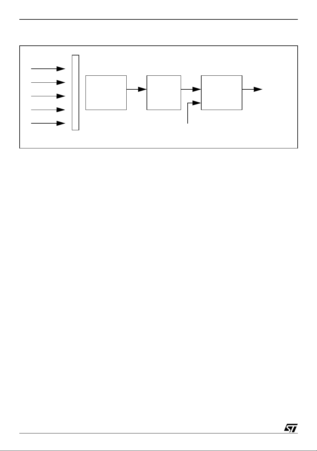
1.5 TYPICAL PIR DETECTOR (CONVENTIONAL)
In conventional dete ctors, the IR radiation is foc used by the Fresnel lens on the PIR sen sor
and then the output of PIR sensor ( which is very sm all in amplitu de) is amplified by an OPAMP based amplifier. The OP-AMP also works as low pass filter and rejects the high frequency signals (more than 10Hz typically). The output of the amplifier is connected to the
comparator which compares the signal to the threshold level. An alarm is raised/light source is
powered if the reference (threshold) voltage is crossed.
5/17
Page 6
PIR (PASSIVE INFRARED) DETECTOR USING ST7FLITE05/09/SUPERLITE
Figure 3. Conventional PIR detector
IR Radiation
PIR Sensor
Amplifier Comparator
Output
Reference Voltage
Fresnel lens
1.6 ADVANTAGES O F ST7LITE PIR (COMPARED TO CONVENTIONAL DESIGN)
1. Transistors are used instead of Op-Amps for amplification. This is a low cost solution.
2. Internal RC oscillator of ST7Lite is used - No need for external oscillator.
3. Calibration of internal RC using engineering calibration values available in flash, for gener-
ating 1MHz. We use PLL in x8 mode to obtain f
CPU
= 8 MHz.
1.7 FEATURES
1.7.1 Tampering detection
An alarm can be switched on if anybody tries to damage/steal the mounted PIR detector. This
can be done by designing the detector in two parts. One part is screwed to the wall and the
second part contains the circuitry and sensor. Removing/stealing one or other part will put the
tamper switch in ON state . Thi s is dete cted b y the m icrocont roller w h ich swi tches th e al ar m
ON. Port PA3 (configured as input pull up) is used to detect tamper. PB2 is a push button
which remains pressed as long as the two parts are attached. When one part is removed, PA3
becomes high and further action (e.g. switching on a alarm) can be taken.
Three pin connector J1 can be used for LED indication or for Relay operation by inserting the
two pin jumper accordingly.
1.7.2 Relay/LED indication option
User can select the LED or relay output for motion indication using three pin connector J2.
LED indication can be used while testing/checking the performance and the relay can be used
in the final application.
6/17
Page 7

PIR (PASSIVE INFRARED) DETECTOR USING ST7FLITE05/09/SUPERLITE
1.7.3 Hardware Self-Test
Hardware self-testing is per formed eac h time t he c ircuit is pow ered-ON or at mi crocontroller
reset. The hardware problem can be indicated by a dedicated LED (D1). In this test, the status
of the transistor Q1 (BC557) collector is checked with respect to the signal at the base of transistor Q3 (BC547) thus confirming the proper working of the transistor circuitry. LED(D1) gets
ON till hardware test routine executes.
1.7.4 LED Indicators
There are six LEDs (D1-D5,D7) in the circuit for indicating different status types, as explained
below:
LED Purpose Description
Led D1 Fault
Led D2 Free
Led D3 Heart Beat It blinks to show that the microcontroller is working properly.
Led D4 Tamper indicator
Led D5
Led D7
Movement
indicator
Power supply
indicator
This LED shows the result of hardware self test. LED Blinking i ndicates
some hardware (transistor circuitry) fault.
Available for user requirements. The port pin is configured as output
push-pull high.
LED ON means tampering occurred, selected by putting jumper J11
and removing J10.
LED ON means human movement detected.
LED ON shows that the circuit is receiving power.
1.7.5 Sensitivity Selection
The system can be made more or less sensitive by assigning high or small values to the parameters used to take movement detection decision. The parameters can be changed in a
function “sel ect_sensitivity()” defined in “main.c”. At one tim e tw o values ca n be as signed to
the parameters and the selection for any value can be done by using jumper J8 (connected to
pin PB1 through a 10KΩ resistor).
1.7.6 ICP connector
ICP (In circuit Programmer) connector can be used to program the device on the circuit.
7/17
Page 8

PIR (PASSIVE INFRARED) DETECTOR USING ST7FLITE05/09/SUPERLITE
1.7.7 Debugging feature
Variable monitoring using RS232 communication
Some parameters can be monitored by connecting the Serial port of a PC to the DB9 connector on board. This is useful in debugging.
The variable to be m onitored c an be selected in the so ftware using a m acro. Pl ease refer to
the software for the meaning of the different variables. By default the ‘Low_var’ variable is
transmitted. Changes in its value can be monitored using the Windows Hyperterminal application. Normally the maximum variation in its value should be around 15.
Similarly, other variables (like out_of_threshold, high_v etc) can also be transmitted and can
be displayed using Hyperterminal. These variables change only when a human motion is detected otherwise they remain almost constant.
The implementation of the SCI transmission between the board and the PC is explained in
Section 2.2.
2 SOFTWARE IMPLEMENTATIO N
These sections describe the algorithms and progr amming techniques implemented in the various modules in the software. First, the flowcharts are shown and then each module is explained.
8/17
Page 9

PIR (PASSIVE INFRARED) DETECTOR USING ST7FLITE05/09/SUPERLITE
Figure 4. Main Routine Flowchart (P art 1 of 2)
START
Set the biasing signal HIGH and provide
a delay to let the capacitor charge
Is ADC input
No
signal HIGH?
Hardware Problem
Set the biasing signal LOW and provide
short delay to let capacitor discharge
Yes
Hardware
check
Is ADC Input
No
signal LOW?
Yes
Set biasing Signal HIGH
Yes
Enable Timer (AR Timer) Interrupt
Make a buffer of 10 integers to store 10 consecutive values of Low_var
Low_var: A variable that counts the number of times that were needed to make
the biasing signal LOW to keep the ADC input signal at threshold level (3V in the
software).This is done in the Timer ISR.
Is ADC input
signal<
Threshold?
No
with interrupt time 52µs
Stabilization
A
9/17
Page 10

PIR (PASSIVE INFRARED) DETECTOR USING ST7FLITE05/09/SUPERLITE
Figure 5. Main Routine Flowchart (P art 2 of 2)
A
NO
Convert the variable (which is to be checked at hyper terminal) into ASCII
and transmit the ASCII data through one port PA5 Pin at baud rate 4800
Find the difference between the previous stored value
(no of times biasing signal made low) and current value of low_var.
No
A
Is a new value of
Low_var received?
YES
Is Difference >
variation Limit
Yes
Decision Block
10/17
Find the difference between the current and maximum,
minimum v a lues of low_v a r.
No
A
Alarm or LED indication for desired duration (may
be permanent ON of Alarm/LED)
Is Difference >
variation Limits
Yes
A
Page 11

PIR (PASSIVE INFRARED) DETECTOR USING ST7FLITE05/09/SUPERLITE
o
Figure 6. Timer ISR (Interr up t Service routine) Flowchart
START
Write the first level to be output on PA5 pin according to the data (ASCII)
to be transmitted at selected baud rate
Change the level of the port pin PA5 according to the ASCII data after every
416µs (52x8=8th occurence of timer interrupt) for baud rate 2400 and
208 µs for 4800 baud rate.
SCI
Transmission
Make Biasing
signal HIGH
Is ADC
input signal
> Threshold?
Decrement counter
Does
Counter=Number
of conversions?
(e.g.1000)
No
YesNo
Make Biasing signal LOW and i ncrement low_var, to count the
number of times the signal is
made LOW
Yes
Counter=Number of conversions
Store low_var value in buffer
Sigma-Delta
Implementati
IRET
11/17
Page 12

PIR (PASSIVE INFRARED) DETECTOR USING ST7FLITE05/09/SUPERLITE
2.1 SIGMA-DELTA IM PLEMENTATION
Sigma-Delta (as shown in Figure 7) needs an integrator, comparator and digital filter for 1 bit
DAC.
Figure 7. Sigma-Delta Conversion concept
Comparator
+
Integrator
-
V
1 Bit DAC
REF
+
-
Digital
Filter
Note: Refer to AN1827 for more details on Sigma-Delta implementation
These components are implemented in the application as follows:
– Comparator: On-chip ADC is used
– 1-Bit DAC: I/O Port PB2 is used
– Integrator: External Resistor and capacitor.
The Sigma-Delta software procedure is as follows:
1.Fix a threshold level for the transistor output (measured by the microcontroller’s ADC
input). This is selected as 3V (96h) in our application.
2. Configure the AR Timer to generate an overflow interrupt every 52 µs.
3.Read the value of the transistor Q1 output signal in ISR (interrupt service routine) using the
microcontroller’s ADC input.
4. Make the PWM sign al HIGH if the ADC input is less than the threshold level.
5. Make the PWM signal LOW if the ADC input is greater than the thresh old level.
By reading the output signal of transistor Q1 with the on-chip ADC, the biasing signal (1-bit
DAC) is adjusted by software.
On motion detection, the signal from the sensor tries to c hange the threshold voltage l evel. But
as the threshold voltage is kept at a fixed level by the biasing signal, this leads to a change in
the duty cycle of the biasing signal. Thi s v ariation in the duty cycle can be detected by calculating the number of times the biasing signal (calculated by variable low_var as also shown in
flow chart) is made LOW in a fixed time, 52msec (1000 times the periodic interrupt) in our software.
12/17
Page 13

PIR (PASSIVE INFRARED) DETECTOR USING ST7FLITE05/09/SUPERLITE
2.2 SCI IMPLEMENTATION USING THE MICROCONTROLLER STANDARD I/O PORTS
A Serial Communications Interface (SCI) is used to allow the user to check different variables
while the application is running. The value of the variables can be displayed on a PC with the
Hyperterminal application. SCI is implemented using standard I/O ports. We just need to
transmi t the da ta fro m the mi crocon tro ller to a PC, so only SCI trans mit is implem ented for
4800 or 2400 ba ud rate (selec table by a macr o in t he softwar e). This i s implemen ted as follows:
1. Convert the variable to be transmitted into ASCII data. This is required because Hyperter-
minal displays ASCII data only.
2. The ASCII data is transmitted bit-by-bit with a bit duration depending on the Baud Rate
selected in the software.
For example:
1 bit duration = 416µs (1/2400 seconds) for 2400 baud
= 208µs (1/4800 seconds) 4800 baud
This bit duration is calculated with the help of the Timer interrupt which is configured for 52µs.
So we can change the statu s of PA 5 Pin afte r 416µs(52x 8) or 208µs (52x4). The time period
for each data bit will be the same.
3. Transmit the Start bit. To do this, hold the PA5 pin LOW for 1 bit time.
4. After the start bit, change the PA5 pin level according to the data (ASCII) to be tr ansmitted.
5. Then, transmit the Stop bit. To do this, hold the PA5 pin HIGH for 1 bit time.
13/17
Page 14

PIR (PASSIVE INFRARED) DETECTOR USING ST7FLITE05/09/SUPERLITE
3 APPLICAT ION SPECIFICATIONS
3.1 CODE SIZE
Code size = 1.2 KBytes (with SCI implementation included)
=969 Bytes (without SCI Implementation, Code size less than 1K): Superlite can be used.
3.2 SIGMA-DELTA CONVERSION TIME
This is equal to the time taken to calculate a digital value after implementing the sigma-delta
algorithm.
Conversion Time= Timer interrupt time* Number of samples
Where Timer interrupt time = 52µs.
The AR timer is configured to generate an overflow interrupt every 52µs. In the Interrupt rou-
tine the software checks the ADC value and then decides the value for biasing signal (1-bit
DAC),
Number of samples = 1000 = Number of times the status of the DAC bit is decided. A software
counter is incremented each time the DAC status made LOW. The ADC is used as a comparator in the application.
Conversion Time= (52µs)x(1000) = 52ms.
3.3 POWER CONSUMPTION
Input voltage must be greater than 9V. The values shown in table are given without relay and
MAX232 cicuitry
Table 1. Current consumption
Sr.No. Power LED Heart Beat LED Detection LED Current Drawn (Normal conditions)
1 OFF OFF OFF 13mA
2 OFF OFF ON 26mA
3ON OFF OFF 26mA
4ON OFF ON 39mA
5ON ON OFF 39mA
6ON ON ON 51mA
3.4 DETECTION RANGE
Without Fresnel lens: 10” approx.
14/17
Page 15

PIR (PASSIVE INFRARED) DETECTOR USING ST7FLITE05/09/SUPERLITE
3.5 POWER SUPPL Y OPTIONS
There can be power supply options, for example:
– Capacitive power supply.
– Linear regulator (shown in the circuit)
– Battery powered: in this case, LEDs can be deactivated to reduce the power consumption.
Current consumption data provided above can help in this case.
4 BILL OF MATERIALS
Table 2. Bill of materials
Part Name/Number Description Quantity Component symbol
ST7Lite05/Superlite Microcontroller 1 U1
L7805 Voltage Regulator 1 U2
ST23 2 Line Driver 1 U3
BC557 PNP Transistor 3 Q1,Q4,Q5
PIR Sensor PIR sensor 1 Q2
BC547 NPN Transistor 1 Q3
1uF Tantalum Capacitor 4 C11-C14
1uF Ceramic Capacitor 1 C7
100nF Ceramic capacitor 7 C1-2,C4-6,C9-10
47uF Electrolytic Capacitor 1 C3
1000uF Electrolytic Capacitor 1 C8
LED LED 6 D1-D5,D7
IN4007 Diodes 6 D6,D8-12
1K Resistor 0.25W 1 R7
100K Resistor 0.25W 4 R5,R11,R13,R15
270 Ohm Resistor 0.25W 6 R2,R3,R8,R10,R16R18
220K Resistor 0.25W 1 R6
47K Resistor 0.25W 1 R4
1M Resistor 0.25W 1 R14
10K Resistor 0.25W 6 R1,R9,R12,R17, R19-20
ICP Connector 10 pin ICP Connector 1 P1
DC_Jack Input supply connector 1 P2
DB9 9 Pin D-Sub connector Female 1 P3
J8 2 Pin Jumpers 1 J8
J1,J2 3 Pin Jumper 2 J1,J2
Push-button PushButton 2 PB1,PB2
15/17
Page 16

PIR (PASSIVE INFRARED) DETECTOR USING ST7FLITE05/09/SUPERLITE
5 SUPERLIT E COM PATIBILITY
The firmware is compatible with Superlite if software-SCI transmission is not required. You
can use ST7Lite05/09 for testing and if any other feature is to be added.
For production purposes, low cost Superlite device can be used.
To make the firmware compatible with Superlite,
(I) Enable “#define SUPERLITE” in main.h.
(II) Modify the configuration file (MAK file) accordingly. The software contains a separate PRM
file for Superlite.
6 RELATED DOCUMENTS
1. ST6 AN434 -Human movement detecting concept
2. ST7LITE05 Datasheet
3. AN1827 - Implementation of Sigma-Delta ADC with ST7FLITE05 /09
16/17
Page 17

PIR (PASSIVE INFRARED) DETECTOR USING ST7FLITE05/09/SUPERLITE
“THE PRESENT NOTE WHICH IS FOR GUIDANCE ONLY AIMS AT PROVIDING CUSTOMERS WITH INFORMATION
REGARDING THE IR PRO DUCT S IN OR DER FO R THEM TO SAV E TIME . AS A RES ULT, STMIC ROEL ECTR ONI CS
SHALL NOT BE HELD LIABLE FOR ANY DIRECT, INDIRECT OR CONSEQUENTIAL DAMAGES WITH RESPECT TO
ANY CLAIMS ARISING FROM THE CONTENT OF SUCH A NOTE AND/OR THE USE MADE BY CUSTOMERS OF
THE INFORMATION CONTAINED HEREIN IN CONNECTION WITH THEIR PRODUCTS.”
Information furnished is believed to be accurate and reliable. However, STMicroelectronics assumes no responsibility for the consequences
of use of such information nor for any infringement of patents or other rights of third parties which may result from its use. No license is granted
by implic ation or oth erwise unde r any patent or patent r i ghts of STMi croelectroni cs. Speci fications me ntioned in this publicat i on are subject
to change without notice. This publication supersedes and replaces all information previously supplied. STMicroelectronics products are not
authorized for use as critical components in life su pport device s or systems without express written approval of STMicroelectronics.
The ST logo is a register ed t rademark of ST M i croelectroni c s.
All other nam es are the pro perty of their respective ow ners
© 2004 STMi croelectroni cs - All rights reserved
STMicroelectron i cs GROUP OF COMPANIES
Australia – Belgium - B razil - Canad a - China – Czech Republic - Finl and - France - Ger many - Hong Kong - India - Israel - Italy - Japan -
Malaysia - Malta - Morocco - Singapore - Spain - Sweden - Switzerland - United Kingdom - United States
www.st.com
17/17
 Loading...