

Page 1

AN1799
APPLICATION NOTE
STR71x GPIO
SCANNING A 4x4 MATRIX KEYPAD
INTRODUCTION
The aim of this application note is to show how to scan the 4x4 matrix keypad multiplexed with
a four 7-segment display. The software attached to this application note scans the pressed
key and displays it on the multiplexed 7- segment LEDs.
This application note describes how the interrupt capability of the STR710 device is used to
offer a better key scan.
Rev. 2
AN1799/0205 1/7
1
Page 2
STR71x GPIO SCANNING A 4x4 MATRIX KEYPAD
1 HARDWARE LAYOUT
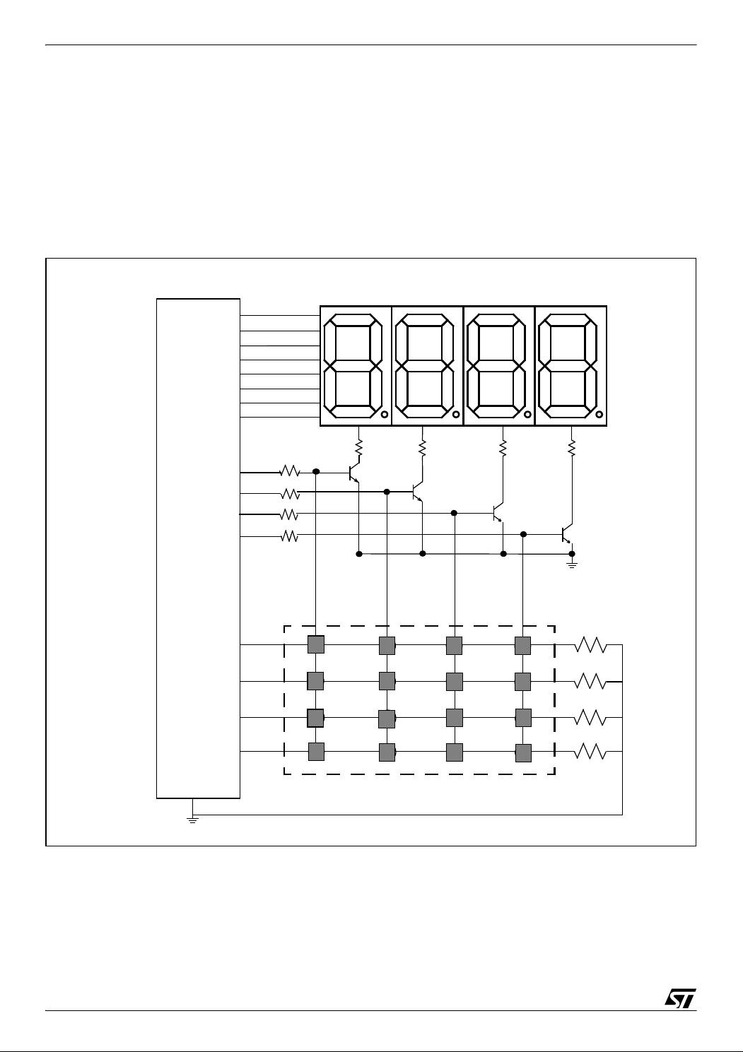
A 4x4 keypad can be very easily interfaced to the STR710’s PORT1 & PORT2 (Figure 1).
Eight lines (P1.0 - 7) are assigned to LED segments. Four lines (P1.8 - 11) are used to drive
and select the 7-segment displays through sink transistors. The same lines are used for
pressed key checking. Keypad rows are connected with pull-down resistors to the four exter
nal interrupts pins (P2.8 - 11).
Figure 1. Multiplexing matrixed keypad with four 7-segment displays
4 x 7-segment displays
P1.0
P1.1
P1.2
P1.3
P1.4
P1.5
P1.6
P1.7
a
b
c
d
e
g
DP
LED Module
f
-
P1.8
P1.9
P1.10
P1.11
STR710
P2.8
P2.9
P2.10
P2.11
1.2K
1.2K
1.2K
1.2K
1
4
7
E
0.33K
0.33K
0.33K
NPN
BC 547C
NPN
BC 547C
NPN
BC 547C
23A
5
8
0
4x4 KEYPAD
6
9
F
B
C
D
0.33K
NPN
BC 547C
0.12K
0.12K
0.12K
0.12K
2/7
2
Page 3

STR71x GPIO SCANNING A 4x4 MATRIX KEYPAD
2 STR710 CONFIGURATION
This part is dedicated to show the STR710 Microcontroller configuration. The STR710 is used
since it offers the possibility to use external interrupts.
2.1 GPIO PORT CONFIGURATION
Rows are connected to P2.8-11 pins configured as Input Pull Up /Pull Down Weak Push-Pull
mode. For the columns, the sink transistors base pins are connected to P1.8-11 pins config
ured as Output Push-Pull. External interrupts are triggered by a high level applied to a pin of
P2.8-11 (caused by a pressed key), they generate an interrupt on the external interrupt (XTI)
channel and can wakeup the system from STOP mode.
P1.0-7 configured as Output Push-Pull to send the value of the pressed key to the desired 7
segment display.
2.2 XTI CONFIGURATION
The External Interrupts Unit (XTI) manages 14 external interrupt lines.
-
In this aplication the XTI is configured to generate interrupts when a rising edge is detected on
line 2-5; any transition from low to high level on the P2.8-11 pins will trigger an external inter
rupt.
-
3/7
Page 4

STR71x GPIO SCANNING A 4x4 MATRIX KEYPAD
3 SOFTWARE
3.1 KEYPAD
The keypad used is a 4x4 matrixed keypad. Rows are connected to the P2.8-11 pins configured as Input Pull Up /Pull Down Weak Push-Pull mode and pulled low through pull-down resistors. Columns are connected to the P1.8-11 pins configured as Output Push-Pull.
Biasing is achieved by setting high (3.3 V) each row for 5 ms duration every 20 ms. This gives
an update rate of 50 Hz. The 5 ms time-base can be generated using a timer overflow inter
rupt.
When a key is pressed, a rising edge is applied to the row the key belong. The MCU executes
the XTI IRQ handler routine and decodes the pressed key (
The keypad is coded as follows:
Table 1. Key codes
Key Row value Column value Key Code
Table 1).
-
0 0x0800 0x0400 0x84
1 0x0100 0x0800 0x18
2 0x0100 0x0400 0x14
3 0x0100 0x0200 0x12
4 0x0200 0x0800 0x28
5 0x0200 0x0400 0x24
6 0x0200 0x0200 0x22
7 0x0400 0x0800 0x48
8 0x0400 0x0400 0x44
9 0x0400 0x0200 0x42
A 0x0100 0x0100 0x11
B 0x0200 0x0100 0x21
C 0x0400 0x0100 0x41
4/7
D 0x0800 0x0100 0x81
E 0x0800 0x0800 0x88
F 0x0800 0x0200 0x82
Page 5

STR71x GPIO SCANNING A 4x4 MATRIX KEYPAD
3.2 DISPLAYS
Depending on which display is selected, and using a Hexadecimal to 7-segment display correspondance table, the corresponding key code is extracted, then decoded to a 7-segment
display and finally sent to the 7-segment LED display.
3.3 FLOWCHARTS
main
Configure XTI
Configure GPIO ports
Configure Timer 0
Configure EIC
Displayer = 0
KeyPressed = True
Ye s
KeyPressed = False
Display Pressed Key
Displayer = Displayer +1
Displayer = 4
No
Ye sNo
5/7
Page 6

STR71x GPIO SCANNING A 4x4 MATRIX KEYPAD
T0TIMI_IRQHandler
Clear the T0 overflow flag
Turn Off all 7-segment LED displays
Send digit to display
Turn on 7-segment displays
End T0TIMI_IRQHandler
XTI_IRQHandler
Clear XTI pending bits
KeyPressed = True
Read Pressed Key Code
Key released = True
Ye s
End XTI_IRQHandler
No
6/7
Page 7

STR71x GPIO SCANNING A 4x4 MATRIX KEYPAD
“THE PRESENT NOTE WHICH IS FOR GUIDANCE ONLY AIMS AT PROVIDING CUSTOMERS WITH INFORMATION
REGARDING THEIR PRODUCTS IN ORDER FOR THEM TO SAVE TIME. AS A RESULT, STMICROELECTRONICS
SHALL NOT BE HELD LIABLE FOR ANY DIRECT, INDIRECT OR CONSEQUENTIAL DAMAGES WITH RESPECT TO
ANY CLAIMS ARISING FROM THE CONTENT OF SUCH A NOTE AND/OR THE USE MADE BY CUSTOMERS OF
THE INFORMATION CONTAINED HEREIN IN CONNECTION WITH THEIR PRODUCTS.”
Information furnished is believed to be accurate and reliable. However, STMicroelectronics assumes no responsibility for the consequences
of use of such information nor for any infringement of patents or other rights of third parties which may result from its use. No license is granted
by implication or otherwise under any patent or patent rights of STMicroelectronics. Specifications mentioned in this publication are subject
to change without notice. This publication supersedes and replaces all information previously supplied. STMicroelectronics products are not
authorized for use as critical components in life support devices or systems without express written approval of STMicroelectronics.
The ST logo is a registered trademark of STMicroelectronics.
All other names are the property of their respective owners
© 2005 STMicroelectronics - All rights reserved
STMicroelectronics group of companies
Australia – Belgium - Brazil - Canada - China – Czech Republic - Finland - France - Germany - Hong Kong - India - Israel - Italy - Japan -
Malaysia - Malta - Morocco - Singapore - Spain - Sweden - Switzerland - United Kingdom - United States of America
www.st.com
7/7
 Loading...