

Page 1

AN1780
APPLICATION NOTE
STR71X REAL TIME CLOCK APPLICATION EXAMPLE
INTRODUCTION
The purpose of this application note is to explain how to use the STR71x Real Time Clock
(RTC) peripheral.
eral, in terms of prescaler and interrupts, to be used to keep the time and date and to generate
Alarm interrupts
counters are designed to continuously count time in seconds. This application note addresses
how to convert the 32-bit time value into a date and time value that can be put in the following
form MM/DD/YYYY, HH:MM:SS.
The date used in this application note is the same used with the UNIX operating system, the
reference date January 1, 1970, often referred to as Unix Epoch.
This document in organized in two sections, the first presents the STR71x RTC peripheral and
how to configure it and generate a fixed time base, the second part describes the related soft
ware required for the application.
As an application example, it demonstrates how to setup the RTC periph-
.The STR71x RTC has a 32-bit binary counter register. The 32-bit binary
-
-
This application note deals with various techniques for keeping time with the STR71x.
For more information about the STR71x RTC peripheral refer to STR71x Reference Manual.
Note: Because of the reference date used and the use of a 32-bit counter, this algorithm rolls
over on Tuesday, January 19, 03:14:07, 2038.
The following application note developed using RVDK Toolchain V1.6.1 and the STR710 Evalboard.
You must have the ARM Real View Developer Kit to get the most out of this Application Note.
AN1780/1204 1/9
1
Page 2
STR71X REAL TIME CLOCK APPLICATION EXAMPLE
1 WHAT IS A REAL TIME CLOCK?
A real time clock is a clock that keeps track of the time even when the system is turned off. In
contrast, clocks that are not real-time do not function when the system is off. Most of the realtime clocks operate at 32.768KHz.
2 APPLICATIONS—TIME AND ATTENDANCE
Real Time Clocks are usually found in portable systems such as a data collection terminals
and smart card readers which are required to keep track of the day and time of certain tasks
taking place. After the tasks are completed, usually the portable system will return to a standby mode to conserve power. The alarm can be set to wake up the system at certain time inter
vals to perform other tasks or to repeat the process. For example, in an access control application, when someone tries to access the building through certain doors, the day and time of
the entry is recorded and this information can be used for accounting and security purposes,
etc.
-
3 STR71X RTC PERIPHERAL
The RTC peripheral implemented in the STR71x family is a 32-bit continuously running
counter that can be used, with a few configuration parameters, to provide a precise clock-cal
endar function.
The RTC peripheral is mapped on the APB2 bridge and clocked by an external 32.768 kHz oscillator through a 32-bit prescaler register, this prescaler can be used to vary the RTC clock
from 32.768 kHz to 0.5 Hz.
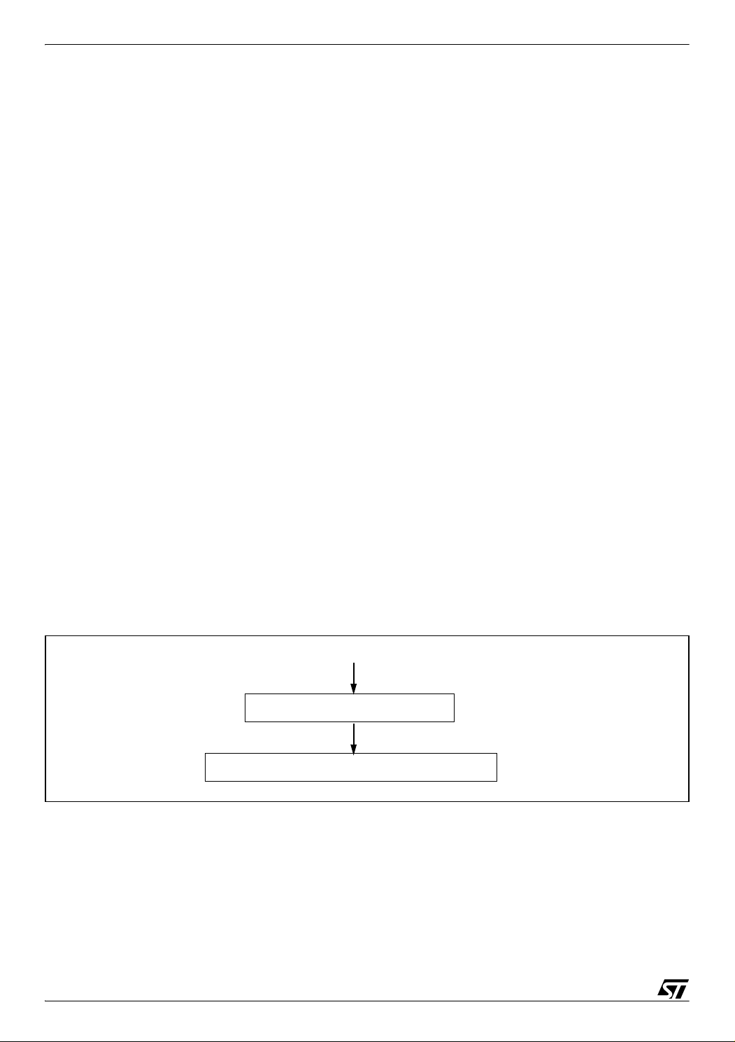
Figure 1. RTC Peripheral
32.768 kHz
20-bit Prescaler register
RTC (32-bit) programmable Counter Registers
In this application, the RTC counter registers have to be incremented every second, this can
be configured by using a prescaler value of 0x8000 (32768) to slow down the RTC clock from
32768 Hz to 1 Hz. This allows the RTC to keep time in seconds in the 32-bit counter.
-
2/9
2
Page 3

STR71X REAL TIME CLOCK APPLICATION EXAMPLE
4 CONFIGURATION MODE
To write in the RTC_PRL, RTC_CNT, RTC_ALR registers, the peripheral must enter Configuration mode. This is done by setting the CNF bit in the RTC_CRL register.
In addition, writing to any RTC register is only enabled if the previous write operation is finished.
To enable the software to detect this situation, the RTOFF status bit is provided in the
RTC_CR register to indicate that an update of the registers is in progress. A new value can be
written to the RTC counters only when the RTOFF status bit value is ’1’.
Configuration Procedure:
1. Poll RTOFF, wait until its value goes to ‘1’
2. Set CNF bit to enter configuration mode
2. Write to one or more RTC registers
3 Clear CNF bit to exit configuration mode
The write operation only executes when the CNF bit is cleared and it takes at least two
Clock32 cycles to complete.
5 32-BIT COUNTER TIME CONVERSION
This application note explains how to convert the 32-bit time value into a date and time value
that can be put in the form of MM/DD/YYYY, HH:MM:SS. Many functions provided by the ARM
compiler used to convert from a date and time to seconds are also described.
These functions are modified in order to explore the STR71x RTC to deliver time and date.
5.1 C LIBRARY FUNCTIONS USED
5.1.1 RTC prescaler Initialisation:
Before start-up we must adjust the STR71x RTC prescaler register value in order to have the
RTC counter registers incremented every second, this can be configured by using a prescaler
value of 0x8000 (32768) to slow down the RTC clock from
5.1.2 Origin Date Adjust
Since the date used in this application note is the same used with the UNIX operating system,
the reference date January 1, 1970, often referred to as Unix Epoch, we must
0x3FF36300 to the value obtained from the STR71x RTC Counter register with intent to have
a start date = 01/01/2004.
32768 Hz to 1 Hz.
add this number
3/9
Page 4

STR71X REAL TIME CLOCK APPLICATION EXAMPLE
NOTE: 0x3FF36300 is the number of seconds from 01/01/1970 to 01/01/2004.
5.1.3 C Functions used
5.1.3.1 localtime
Converts time in seconds since Unix Epoch to local time.
■ SYNOPSIS
#include <time.h>
extern struct tm *localtime(const time_t * /*timer*/);
■
Description
Converts the calendar time pointed to by timer into a broken-down time, expressed a local
time.
■ Returns
Returns pointer (ptim) to static data, it converts a time as returned by the time function to a
9-element list with the time analysed for the local time zone. Typically use the following tm
structure:
struct tm {
int tm_sec; /* seconds after the minute, 0 to 60 (0 - 60 allows for the occasional
leap second) */
int tm_min; /* minutes after the hour, 0 to 59 */
int tm_hour; /* hours since midnight, 0 to 23 */
int tm_mday; /* day of the month, 1 to 31 */
int tm_mon; /* months since January, 0 to 11 */
int tm_year; /* years since 1900 */
int tm_wday; /* days since Sunday, 0 to 6 */
int tm_yday; /* days since January 1, 0 to 365 */
int tm_isdst; /* Daylight Savings Time flag */
};
5.1.3.2 mktime()
Converts local time to seconds since the Unix Epoch
■ SYNOPSIS
#include <time.h>
extern time_t mktime(struct tm * /*timeptr*/);
■ DESCRIPTION
The mktime() function converts the broken-down time, expressed as local time, in the structure pointed to by timeptr into a calendar time value with the same encoding as that of the
values returned by the time() function.
4/9
Page 5

STR71X REAL TIME CLOCK APPLICATION EXAMPLE
5.1.4 Code Description
This application note addresses how to convert the 32-bit time value into a date and time value
that can be put in the form of MM/DD/YYYY, HH:MM:SS.
The code should be set up so that:
– The UART0 and HyperTerminal are used to enter a current TIME and DATE after start-up.
– The following hyperterminal configuration is used:
■HyperTerminal configuration:
- Bits per second ---- > 38 400
- Data bit ---------------> 8
- Parity ----------------- > None
- Stop bits -------------> 1
- Flow control --------- > None
– After reset, the RTC prescaler is configured to have the RTC counter incremented every sec-
ond.
– Alarm configuration (an alarm is configured after 5s).
– Then enable the RTC alarm interrupt via the EIC configuration.
– A current Date and Time will display on the LCD.
The RTC interrupt service routine:
– Clear the RTC interrupt flag.
– The RTC alarm will be fired after 5 second and the RTC_IRQHandler routine will be execut-
ed. An alarm message will be displayed for 2s and the RTC will be configured to generate
an other alarm interrupt after 5s.
Figure 2 shows the code flow of the algorithm used to convert raw seconds to a date/time.
5/9
Page 6

STR71X REAL TIME CLOCK APPLICATION EXAMPLE
Figure 2. C Code Flow:
main
Use a prescaler value of 0x8000
in order to have the RTC counter
registers incremented every one second
Adjust current Date and Time
using HyperTerminal and UART0
Use localtime function in order to
convert the current date and time
to seconds since Unix Epoch
Substract this number 0x3FF36300
from the result in order to have
reference date first January 2004
Update the RTC device counter
Configure the RTC Alarm
Read the RTC counter register value
RTC IRQHandler
Clear AIR and GIR Bits
Configure an alarm after 5 seconds
Display an alarm message
Add this number 0x3FF36300 to the
counter register value in order to have
a start date = 01/01/70
Use mktime function to Convert
the calendar time pointed to by timer
into a broken-down time
Display time and date
Here is a section of code taken from main.c which performs the steps shown above in Figure
2 above:
#include "71x_lib.h"
#include "lcd.h"
#include <stdio.h>
#include <time.h>
#include <stdlib.h>
#define RTC_PRESC 0x8000
6/9
Page 7

STR71X REAL TIME CLOCK APPLICATION EXAMPLE
time_t TIME;
struct tm *ptim;
RCCU_ResetSources ResetSources;
int main(void)
{
RTC_FlagClear ( RTC_OWIR );
RTC_FlagClear ( RTC_AIR );
RTC_FlagClear ( RTC_SIR );
RTC_FlagClear ( RTC_GIR );
RTC_PrescalerConfig(RTC_PRESC);
ptim=malloc(sizeof(*ptim));
printf("s:");
scanf("%d, ",&ptim->tm_sec);
printf("m:");
scanf("%d, ",&ptim->tm_min);
printf("h:");
scanf("%d",&ptim->tm_hour);
printf("D:");
scanf("%d,",&ptim->tm_mday);
printf("M:");
scanf("%d,",&ptim->tm_mon);
ptim->tm_mon--;
printf("Y:");
scanf("%d",&ptim->tm_year);
ptim->tm_year-=1900;
TIME = mktime(ptim)-0x3FF36300;
RTC_WaitForLastTask();
RTC_EnterCfgMode(); // Enter In Configuration Mode
RTC_WaitForLastTask(); // Wait For Last Task Completion
RTC->CNTL = TIME & 0x0000FFFF;
RTC_WaitForLastTask(); // Wait For Last Task Completion
RTC->CNTH = ( TIME & 0xFFFF0000 ) >> 16;
RTC_WaitForLastTask(); // Wait For Last Task Completion
RTC_ExitCfgMode (); // Exit From Configuration Mode
// RTC_AlarmConfig(TIME+15);
RTC_AlarmConfig(RTC_CounterValue()+5);
EIC_IRQChannelConfig( RTC_IRQChannel, ENABLE );// Enable RTC IRQ channel
EIC_IRQChannelPriorityConfig( RTC_IRQChannel, 1);
EIC_IRQConfig( ENABLE );
RTC_ITConfig( RTC_AIT|RTC_GIT, ENABLE ); // Enable alarm Interrupt
// LCD_UnderlineCursorOff();
gotoxy(1,1);
printf(" ");
gotoxy(1,2);
7/9
Page 8

STR71X REAL TIME CLOCK APPLICATION EXAMPLE
printf(" ");
while(1)
{
TIME=RTC_CounterValue()+0x3FF36300;
ptim = localtime(&TIME);
gotoxy(1,1);
printf(" %02d/",ptim->tm_mday);
printf("%02d/",ptim->tm_mon+1);
printf("%4d\r\n",ptim->tm_year+1900);
gotoxy(1,2);
printf(" %02d : ",ptim->tm_hour);
printf("%02d : ",ptim->tm_min);
printf("%02d\r\n",ptim->tm_sec);
}
}
8/9
Page 9

STR71X REAL TIME CLOCK APPLICATION EXAMPLE
“THE PRESENT NOTE WHICH IS FOR GUIDANCE ONLY AIMS AT PROVIDING CUSTOMERS WITH INFORMATION
REGARDING THEIR PRODUCTS IN ORDER FOR THEM TO SAVE TIME. AS A RESULT, STMICROELECTRONICS
SHALL NOT BE HELD LIABLE FOR ANY DIRECT, INDIRECT OR CONSEQUENTIAL DAMAGES WITH RESPECT TO
ANY CLAIMS ARISING FROM THE CONTENT OF SUCH A NOTE AND/OR THE USE MADE BY CUSTOMERS OF
THE INFORMATION CONTAINED HEREIN IN CONNECTION WITH THEIR PRODUCTS.”
Information furnished is believed to be accurate and reliable. However, STMicroelectronics assumes no responsibility for the consequences
of use of such information nor for any infringement of patents or other rights of third parties which may result from its use. No license is granted
by implication or otherwise under any patent or patent rights of STMicroelectronics. Specifications mentioned in this publication are subject
to change without notice. This publication supersedes and replaces all information previously supplied. STMicroelectronics products are not
authorized for use as critical components in life support devices or systems without express written approval of STMicroelectronics.
The ST logo is a registered trademark of STMicroelectronics.
All other names are the property of their respective owners
© 2004 STMicroelectronics - All rights reserved
STMicroelectronics group of companies
Australia – Belgium - Brazil - Canada - China – Czech Republic - Finland - France - Germany - Hong Kong - India - Israel - Italy - Japan -
Malaysia - Malta - Morocco - Singapore - Spain - Sweden - Switzerland - United Kingdom - United States of America
www.st.com
9/9
 Loading...