


AN1774
APPLICATION NOTE
STR71x SOFTWARE DEVELOPMENT
GETTING STARTED
INTRODUCTION
This document provides an introduction to the STR71x product family. It describes the software environment required to develop an STR71x application from scratch. It summarizes the
different steps needed to configure the development toolset and to use the template software
library to build and to debug a sample STR71x application on the target hardware.
Two software examples are supplied with this application note. Both are intended for users
new to STR71x microcontrollers. The first one is a standard application demonstrating an
input/output pin toggling function. The required steps to create this example project, to build
and debug the image are described in the first chapter. The second one illustrates an advanced example showing the use of interrupts. Both examples are loaded and executed from
the STR71x embedded RAM, and then the target hardware has to be configured consequently
(BOOTEN/1/0=”110”).
The application source files are provided within the package ’AN1774.zip’. This file should be
unpacked into any directory.
This document assumes that the reader is familiar with ARM cores. For more details on the
ARM core architecture, refer to the ARM Developer Suite Guide and the ARM Technical Reference Manual. These documents are available from ARM website.
Rev. 1.3
AN1774/0804 1/9
1

STR71x SOFTWARE DEVELOPMENT GETTING STARTED
1 SOFTWARE SETTINGS
This chapter describes the different steps needed to creating and configuring an STR71x
project. Neither the toolset installation nor the licence management are described in this application note. This document assumes that the toolset is already installed on the development
host. For more details on RealView toolset installation and licences’ management, refer to the
RealView Debugger Installation Guide for Windows.
For more details on creating and running applications, refer to the RealView Debugger Essentials Guide. RealView Debugger documents are available from the ARM website.
The ARM RealView provides a graphical user interface tool for managing your software development projects.
This section describes the steps required for creating, building and debugging an STR71x
standard application using the RealView toolset. This application consists of toggling the I/O
port 0 peripheral pins. The I/Os, configured as push-pull outputs, are toggled in an endless
loop every 130 ms (the external clock operates at a frequency of 16 MHz).
The application source code files are located in the example 1 of ’AN1774.zip’ file and are
made of, besides the standard files described in Section 2.1, the ‘main.c’ file containing the
main routine.
1.1 STARTING REALVIEW DEBUGGER
To start the RealView Debugger:
■ Select Start->Programs->ARM->ARM RealView Developper Kit for ST from the
Windows Start menu,
■ Select RealView Debugger from the menu.
RealView Debugger starts and the default Code window is displayed. This window is your debugging and editing window.
The appearance of the Code window depends on your licenses. For further information about
this window contents, refer to the RealView Debugger Essentials Guide.
1.2 CREATING A NEW PROJECT
The following steps describe how to create a new project.
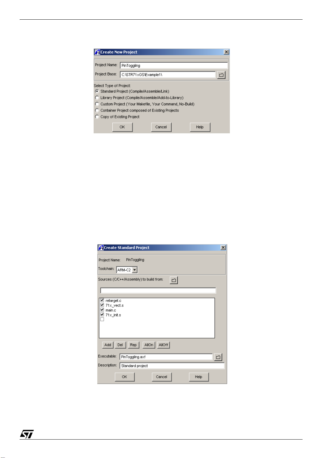
■ Select Project->New project... from the default Code window main menu. A Create New
project dialog box is displayed (see the figure below),
■ Enter ’PinToggling’ as the project name in the Project Name field,
■ Click the folder icon and choose <Select Dir...> to locate the project base directory,
2/9
2
STR71x SOFTWARE DEVELOPMENT GETTING STARTED
■ Select Standard project (Compile/Assemble/Link) as project type,
■ Click OK to confirm your entries and close the Create New Project window.
1.3 DEFINING A STANDARD PROJECT
Once the Create New Project window is closed the Create Standard project dialog box is displayed (See the figure below).
■ Select "ARM-C2" in the Toolchain field.
■ Specify the Sources (C/C++/Assembly) to build from by clicking the directory icon. The
project base directory, defined previously, is opened. Select the source files to be added to
the source list box: use Shift or Ctrl keys. The files: retarget.c, 71x_vect.s, main.c and
71x_init.s must be selected to be included in the build process.
The Real View Debugger completes the Executable field with the project name (PinTog-
gling.axf) and the Description field as Standard project. Then click OK to create the project.
3/9

STR71x SOFTWARE DEVELOPMENT GETTING STARTED
1.4 PROJECT SETTINGS
RealView Debugger displays the Project Properties window, shown in the figure below, to
allow you to customize the project. This window contains all the project details such as source
file, project path and compilation parameters.
Settings Values
List of entries
Pane
pane
■ Double-Click on *COMPILE=arm group in the List of Entries pane and choose
Preprocessor. Right-click on the Include setting in the Settings Values pane, and select
Edit as Directory name from the context menu. Use the Enter New Directory Dialog box to
locate the path of the include directories. Set the include directory to
’..\STR71xGS\Example1’ and click Select to confirm your choice.
■ Double-Click on *BUILD group in the List of Entries pane and choose Link Advanced.
Right-click on the Scatter file setting in the Settings Values pane, and select Edit as file
name from the context menu. Use the Enter New filename Dialog box to locate the scatter
file ’scat.scf’ under ’..\STR71xGS\Example1’.
■ Right-click on the Entry setting in the Settings Values pane, and select Edit value from the
context menu. Then enter the name of the entry point in the corresponding field. In our case
the entry point is ’Reset_Handler’.
■ Select File->Save and Close to regenerate the makefiles for the project, and close the
Project Properties window.
1.5 BUILDING THE PROJECT
The project has been configured. You can now build it. Select Tools->Rebuild all
(clean+build) from the Code Window main menu. The build completes and the RealView De-
bugger displays the Build tab, in the output pane, to report successful completion. The application image ’PinToggling.axf’ is generated.
4/9

STR71x SOFTWARE DEVELOPMENT GETTING STARTED
1.6 CONNECTING TO TARGET
The next stage in your debugging session is to connect to your debug target, which is the
STR71x core on your application board. This step assumes that you have already compiled
and built your STR71x image.
If you choose hardware debugging, the MICRO-ICE debugging tool should be plugged in to
both the host and to the target which must be powered on. Ensure that the ICE software is installed and setup as described in the next section MICRO-ICE SETUP.
■ Select File->Connection->Connect to target... from the Code window main menu to
display the Connection Control window, shown in the figure below. Use this window to
connect to your target.
■ The Connection Control window shows all the connections available. In our case, you can
specify one of the these connections: ST-STR710-EVAL. Select the check-box or doubleclick on the connection entry in the Name pane.
■ Now, you can load the built image ’PinToggling.axf’, under ’..\STR71xGS\Example1\
Debug’, on the target by selecting File->Load Image. You can also click the blue hyperlink
Click to Load Image to Target in the File Editor pane.
1.7 DEBUGGING THE APPLICATION
Once the image has been loaded on the target you can debug it. To execute the image click
the Go button on the Actions toolbar.
You can use breakpoints to run the application step by step. A simple double-click on a line
sets a breakpoint on that location. You can display memory and register contents. Select
View->Pane Views->Memory from the Code window to display the Memory pane or View>Pane View->Registers to display the Register pane. By means of these panes you can view
and set the content of a register and a memory location. You can also display variables.
Use an oscilloscope to monitor the GPIO0 pin state.
For more details on RealView debugging features, refer to the RealView Debugger essentials
guide document.
5/9

STR71x SOFTWARE DEVELOPMENT GETTING STARTED
1.8 DISCONNECTING FROM THE TARGET
To disconnect from a target select File->Connection->Disconnect from the Code Window
main menu or double-click the connect entry in the Connection Control window.
For more details on Micro-ICE configuration, refer to RealView ICE user guide.
6/9

STR71x SOFTWARE DEVELOPMENT GETTING STARTED
2 SOFTWARE EXAMPLE
This chapter describes an STR71x software example. The first part enumerates the standard
files required to build an application. The second part describes an application example.
This chapter assumes that both the hardware and the software environments are setup as described previously.
2.1 GENERIC CONFIGURATION FILES
This section describes the standard files required by any STR71x application. These files are
mandatory for building a project for STR71x cores.
The table below enumerates and explains the use of each file.
File Description
71x_vect.s
71x_map.h
71x_init.s
retarget.c
scat.scf
This file contains exception vectors and exception handlers. For this example
RAM is fixed at address 0x0.
This file contains the memory mapping and physical registers address definitions.
This file performs initialization of stack pointers for each mode, Enhanced Interrupt Controller initialization, and branches to __main in the C library.
This file provides a retarget layer for low-level Input/Output. Typically, this con-
tains your own target-dependent implementations of fputc(), ferror(),....Semi-
hosting SWIs are used to display text on the console of the host debugger.
An image is made up of regions and output sections. Every region in the image
can have a different load and execution address. The scatter-loading mechanism enables you to specify the memory map of an image to armlink. For more
information on the scatter file, load and execution regions, refer to the ’ARM
Linker and Utilities Guide’.
7/9

STR71x SOFTWARE DEVELOPMENT GETTING STARTED
2.2 APPLICATION EXAMPLE: INTERRUPT HANDLING
This section implements an application with interrupt handling. The main() function initializes
and starts two timer overflow interrupts.
When a timer expires, an interrupt, handled in 71x_it.c, is generated. Timer0 generates an interrupt every 130 ms which toggles the GPIO0 pin. However Timer1 is configured to generate
an interrupt every 4.2 s and to set GPIO1 pin to high level for 5 s. These timing suppose that
the chip is clocked by an external oscillator operating at a frequency of 16 MHz.
The Timer0 interrupt priority has been set to be higher than the Timer1 priority to allow the
Timer0 T0TIMI_IRQHandler interrupt routine to be served during the execution of the Timer1
T1TIMI_IRQHandler interrupt routine. Figure 1. shows the behaviour of GPIO0 and GPIO1
pins and the Timer0 and Timer1 interrupts.
The example source code is located in the ’..\STR71xGS\Example2’ directory and it contains,
besides the standard files and main.c, the makefiles for the project, the project file Interrup-
tHandling.prj, the interrupt handler file 71x_it.c and the interrupt header file 71x_it.h.
This example has already been built for you. So there is no need to recompile it. You have,
simply, to open the project file Example2.prj in the RealView Debugger, to load the image
Example2.axf into the target and debug it.
For more details on STR71x interrupts’ handling, refer to the Interrupt Handling application
note, supplied within this package, or to the STR71x datasheet.
Figure 1. Timer0 and Timer1 Interrupts handling
Timer0 interrupt
GPIO0 pin
GPIO1 pin
Timer1 interrupt
8/9

STR71x SOFTWARE DEVELOPMENT GETTING STARTED
“THE PRESENT NOTE WHICH IS FOR GUIDANCE ONLY AIMS AT PROVIDING CUSTOMERS WITH INFORMATION
REGARDING THEIR PRODUCTS IN ORDER FOR THEM TO SAVE TIME. AS A RESULT, STMICROELECTRONICS
SHALL NOT BE HELD LIABLE FOR ANY DIRECT, INDIRECT OR CONSEQUENTIAL DAMAGES WITH RESPECT TO
ANY CLAIMS ARISING FROM THE CONTENT OF SUCH A NOTE AND/OR THE USE MADE BY CUSTOMERS OF
THE INFORMATION CONTAINED HEREIN IN CONNECTION WITH THEIR PRODUCTS.”
Information furnished is believed to be accurate and reliable. However, STMicroelectronics assumes no responsibility for the consequences
of use of such information nor for any infringement of patents or other rights of third parties which may result from its use. No license is granted
by implication or otherwise under any patent or patent rights of STMicroelectronics. Specifications mentioned in this publication are subject
to change without notice. This publication supersedes and replaces all information previously supplied. STMicroelectronics products are not
authorized for use as critical components in life support devices or systems without express written approval of STMicroelectronics.
The ST logo is a registered trademark of STMicroelectronics.
All other names are the property of their respective owners
© 2004 STMicroelectronics - All rights reserved
STMicroelectronics GROUP OF COMPANIES
Australia – Belgium - Brazil - Canada - China – Czech Republic - Finland - France - Germany - Hong Kong - India - Israel - Italy - Japan -
Malaysia - Malta - Morocco - Singapore - Spain - Sweden - Switzerland - United Kingdom - United States of America
www.st.com
9/9
 Loading...