


AN1756
Application note
Choosing a DALI implementation strategy
with ST7DALIF2
Introduction
This application note describes how to choose a DALI (Digital Addressable Lighting
Interface) implementation strategy using the ST7DALIF2 microcontroller. As well as
presenting topology options, this document also gives an introduction to the DALI standard
with a description of the protocol and a list of advantages.
Please refer to Section 4 for a list of additional documents referenced in this application
note.
March 2009 Rev 3 1/10
www.st.com

Contents AN1756
Contents
1 High-frequency tube lamp ballast applications . . . . . . . . . . . . . . . . . . . 3
2 Choosing an implementation strategy . . . . . . . . . . . . . . . . . . . . . . . . . . 4
3 DALI standard . . . . . . . . . . . . . . . . . . . . . . . . . . . . . . . . . . . . . . . . . . . . . . 6
3.1 Introduction . . . . . . . . . . . . . . . . . . . . . . . . . . . . . . . . . . . . . . . . . . . . . . . . 6
3.2 DALI standard protocol . . . . . . . . . . . . . . . . . . . . . . . . . . . . . . . . . . . . . . . . 6
3.3 DALI system advantages . . . . . . . . . . . . . . . . . . . . . . . . . . . . . . . . . . . . . . 7
4 References . . . . . . . . . . . . . . . . . . . . . . . . . . . . . . . . . . . . . . . . . . . . . . . . . 8
5 Revision history . . . . . . . . . . . . . . . . . . . . . . . . . . . . . . . . . . . . . . . . . . . . 9
2/10
AN1756 High-frequency tube lamp ballast applications
1 High-frequency tube lamp ballast applications
Basically, a HF-TL ballast converts the 50-60 Hz AC Line input or a DC voltage to a high
frequency output, usually in the range of 25-125 kHz. A rectifier block and a DC to high
frequency inverter usually make up a ballast (please refer to 1 in Section 4: References).
Voltage fed series resonant half bridge inverters are currently used for fluorescent lamps.
This topology allows to easily operate in Zero Voltage Switching (ZVS) resonant mode,
reducing the transistor switching losses and the electromagnetic interference (please refer
to 2 in Section 4: References).
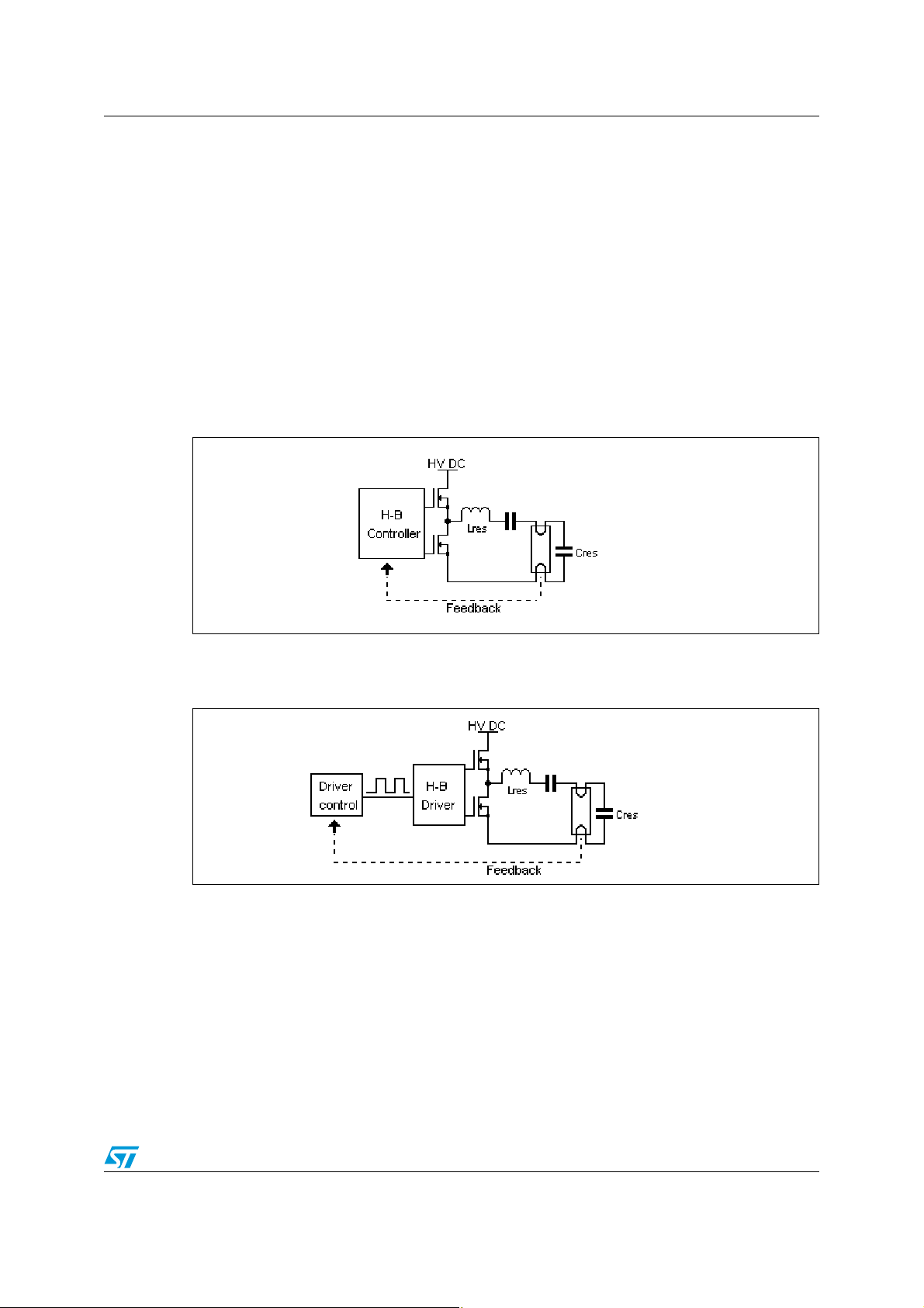
The half bridge of the inverter can be controlled in different ways with different ICs:
● Half-bridge controller like, for example, the L6574.
Figure 1. Typical topology with a half-bridge controller
● Half-bridge driver like, for example, the L6384 + some kind of control.
Figure 2. Typical topology with a half-bridge driver
What is the difference between a half-bridge driver and a half-bridge controller?
A driver is “just” able to drive the floating (high side) transistor of a symmetric half bridge
inverter, from a Pulse Width Modulation (PWM) signal. The controller also includes some
form of oscillator, usually tunable by using a few external components (resistor, capacitor).
Varying the switching frequency is the mainly used control principle. This allows the current
in the lamp, and therefore the output power to be modulated (please refer to 2 in Section 4:
References). So the lamp can be dimmed and input voltage variations can be compensated.
To know more about high frequency tube lamp ballast applications, please refer to 2 in
Section 4: References.
3/10

Choosing an implementation strategy AN1756
2 Choosing an implementation strategy
In order to have a centralized control of each dimmable ballast of a room, a communication
protocol is needed. DALI is an economic solution that is more and more widely possibility
becoming popular in the lighting market. To find out the benefits of DALI, please refer to
document 3 referenced in Section 4
Since DALI is a digital protocol, it needs to handled by a microcontroller like ST7DALIF2.
Various topologies can be used to integrate this digital communication. It can work together
with a ballast controller, just for DALI communication as shown in Figure 3:
Figure 3. Micro handles only communication
or it can do the DALI communication and take the place of the driver control, like in Figure 4:
Figure 4. Micro handles communication AND control
The choice is up to the designer. Whatever solution is chosen, ST is the first semiconductor
manufacturer able to provide both the right high-voltage driver or controller, as well as a
microcontroller with an on-chip decoder for the DALI protocol.
To get more information on the first topology and its advantages, please refer to application
note AN1900 “Hardware Implementation for ST7DALI-EVAL” or order the ST7DALI-EVAL
evaluation kit.
4/10
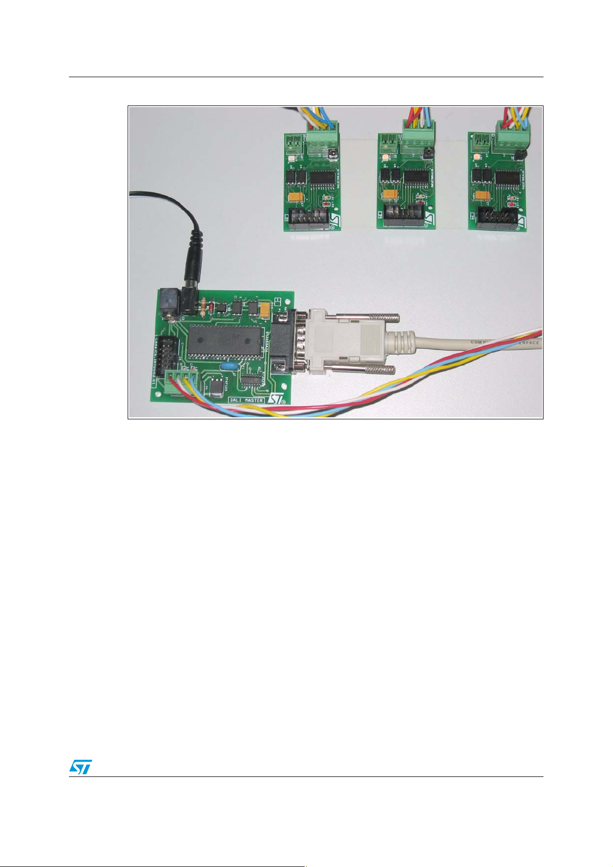
AN1756 Choosing an implementation strategy
Figure 5. ST7DALI-EVAL kit
5/10

DALI standard AN1756
3 DALI standard
3.1 Introduction
DALI is an acronym for Digital Addressable Lighting Interface, standardized as IEC 929.
DALI is the new interface standard for lighting controls solutions defined by the lighting
industry. AG-DALI is the “Digital Addressable Lighting Interface Working Group” established
for joint promotion and application of the DALI Standard by leading manufacturers and
institutions in the field of digital addressing of lamps and/or luminaires. For more
information, refer to document 3 referenced in Section 4.
3.2 DALI standard protocol
The DALI protocol uses the bi-phase Manchester asynchronous serial data format. All the
bits of the frame are bi-phase encoded except the two stop bits.
● The transmission rate is about 1.2 kHz. The bi-phase bit period is 833.33uS ±10%.
● A forward frame consists of 19 bi-phase encoded bits:
– 1 start bit (0->1: logical ’1’)
– 1 address byte (8-bit address)
– 1 data byte (8-bit data)
– 2 high level stop bits (no change of phase)
● A backward frame consists of 11 bi-phase encoded bits:
– 1 start bit (0->1: logical ’1’)
– 1 data byte (8-bit data)
– 2 high level stop bits (no change of phase)
A forward frame consists of 19 bi-phase encoded bits: 1 start bit (logical ’1’), 1 address byte
and 1 data byte. The frame is terminated by 2 stop bits (idle). The stop bits do not contain
any change of phase.
A backward frame consists of 11 bi-phase encoded bits: 1 start bit (logical ’1’) and 1 data
byte. The frame is terminated by 2 stop bits (idle). The stop bits do not contain any change
of phase.
The transmission rate, expressed as a bandwidth, is specified at 1.2 kHz for the forward
channel and for the backward channel.
The settling time between two subsequent forward frames is 9.17 ms (minimum).
The settling time between forward and backward frames is between 2.92 ms and 9.17 ms. If
a backward frame has not been started after 9.17 ms, this is interpreted as “no answer”.
In the event of code violation, the frame is ignored. After a code violation has occurred, the
system is ready again for data reception.
6/10

AN1756 DALI standard
Figure 6. DALI standard frame
Only the ST7DALIF2 microcontroller has a dedicated peripheral for handling the DALI
protocol! For more details, please refer to document 4 referenced in Section 4.
3.3 DALI system advantages
Figure 7. DALI cable
Here are the main advantages of the DALI system:
● Simple wiring: all of the units in the system are interconnected using a simple five-core
cable (see Figure 7).
● No mains switching required: lamps can be dimmed or switched on and off using
control system commands without any need for mains switching.
● Easy system re-configuration: the operation of the system can be changed quickly
without any modification to the hardware.
● Easy system modification: if the lighting system needs to be enlarged, new
components can be added anywhere on the DALI cable.
● It is possible to define light scenes. Scene means: a particular light level intensity. A
maximum of 16 scenes can be defined.
Please refer to document 3 in Section 4 to find out more details of what are the other
benefits of the DALI standard for the end user and for specifiers and architects.
7/10

References AN1756
4 References
1. AN1320: L6574 & microcontroller in ballast applications
2. AN993: Electronic ballast with PFC using L6574 and L6561
3. AG DALI Internet site: http://www.dali-ag.org
4. ST7DALIF2 datasheet
8/10

AN1756 Revision history
5 Revision history
Table 1. Document revision history
Date Revision Changes
30-Nov-2003 1 Initial release.
31-May-2004 2 Added introduction chapter. Updated references.
17-Mar-2009 3 Changed product references from ST7DALI to ST7DALIF2.
9/10

AN1756
Please Read Carefully:
Information in this document is provided solely in connection with ST products. STMicroelectronics NV and its subsidiaries (“ST”) reserve the
right to make changes, corrections, modifications or improvements, to this document, and the products and services described herein at any
time, without notice.
All ST products are sold pursuant to ST’s terms and conditions of sale.
Purchasers are solely responsible for the choice, selection and use of the ST products and services described herein, and ST assumes no
liability whatsoever relating to the choice, selection or use of the ST products and services described herein.
No license, express or implied, by estoppel or otherwise, to any intellectual property rights is granted under this document. If any part of this
document refers to any third party products or services it shall not be deemed a license grant by ST for the use of such third party products
or services, or any intellectual property contained therein or considered as a warranty covering the use in any manner whatsoever of such
third party products or services or any intellectual property contained therein.
UNLESS OTHERWISE SET FORTH IN ST’S TERMS AND CONDITIONS OF SALE ST DISCLAIMS ANY EXPRESS OR IMPLIED
WARRANTY WITH RESPECT TO THE USE AND/OR SALE OF ST PRODUCTS INCLUDING WITHOUT LIMITATION IMPLIED
WARRANTIES OF MERCHANTABILITY, FITNESS FOR A PARTICULAR PURPOSE (AND THEIR EQUIVALENTS UNDER THE LAWS
OF ANY JURISDICTION), OR INFRINGEMENT OF ANY PATENT, COPYRIGHT OR OTHER INTELLECTUAL PROPERTY RIGHT.
UNLESS EXPRESSLY APPROVED IN WRITING BY AN AUTHORIZED ST REPRESENTATIVE, ST PRODUCTS ARE NOT
RECOMMENDED, AUTHORIZED OR WARRANTED FOR USE IN MILITARY, AIR CRAFT, SPACE, LIFE SAVING, OR LIFE SUSTAINING
APPLICATIONS, NOR IN PRODUCTS OR SYSTEMS WHERE FAILURE OR MALFUNCTION MAY RESULT IN PERSONAL INJURY,
DEATH, OR SEVERE PROPERTY OR ENVIRONMENTAL DAMAGE. ST PRODUCTS WHICH ARE NOT SPECIFIED AS "AUTOMOTIVE
GRADE" MAY ONLY BE USED IN AUTOMOTIVE APPLICATIONS AT USER’S OWN RISK.
Resale of ST products with provisions different from the statements and/or technical features set forth in this document shall immediately void
any warranty granted by ST for the ST product or service described herein and shall not create or extend in any manner whatsoever, any
liability of ST.
ST and the ST logo are trademarks or registered trademarks of ST in various countries.
Information in this document supersedes and replaces all information previously supplied.
The ST logo is a registered trademark of STMicroelectronics. All other names are the property of their respective owners.
© 2009 STMicroelectronics - All rights reserved
STMicroelectronics group of companies
Australia - Belgium - Brazil - Canada - China - Czech Republic - Finland - France - Germany - Hong Kong - India - Israel - Italy - Japan -
Malaysia - Malta - Morocco - Singapore - Spain - Sweden - Switzerland - United Kingdom - United States of America
www.st.com
10/10
 Loading...