

Page 1

AN1755
APPLICATION NOTE
A HIGH RESOLUTION / PRECISION THERMOMET ER USING
ST7 AND NE555
INTRODUCTION
The goal of this application note is to present a realistic example of a thermometer using an
ST7 and an NE555.
The NE555 is operating in the a-stable mode. Its frequency is controlled by the resistance
changes of a NTC-thermistor. The frequency, as well as the duty cycle, are measured by the
ST7 timer. The NE555 output is connected to the tim e r input capture pi n.
Rev. 1.0
AN1755/0304 1/7
1
Page 2
A HIGH RESOLUTION / PRECISION THERMOMETER USING ST7 AND NE555
1 DESCRIPTION OF NE 55 5
The NE555 monolithic timing circui t is a hi ghly stable controll er capable of producing accurate
time delays or oscillation. In the time delay mode of operation, the time is precisely controlled
by one external resistor and capacitor. F or a stable operation as an oscil lator , the free runni ng
frequency and the duty cycle are both accurately controlled with two external resistors and
one capacitor. For more details see NE555 datasheet.
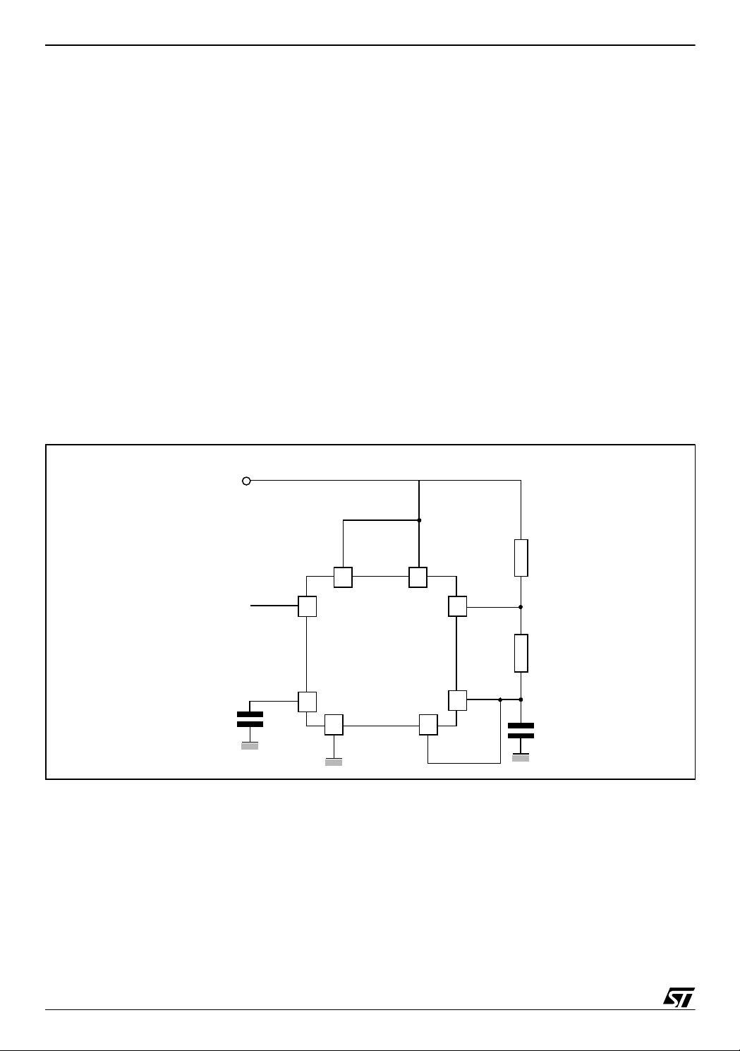
2 ASTABLE OPERATION
The circuit is sho wn in Figure 1. (pin 2 and 6 connect ed). I t triggers itself and operates as a
free running multi vibrator. The external capacitor charges through R
through R
stable mode of operation, C
. Thus the duty cycle is precisely set by the ratio of the se two resistor s. In the a-
2
charges and di scharges betw ee n 1/3 VCC and 2/3 VCC. Due to
1
the self-triggered mode, the charge and discharge times and therefore frequency are independent of the supply voltage.
Figure 1. Circuit Diagram of NE 555 in a-stable mode
and R2 and discharges
1
+
V
= 5V
CC
Output
Control
Voltage
0.01µF
3
5
1 2
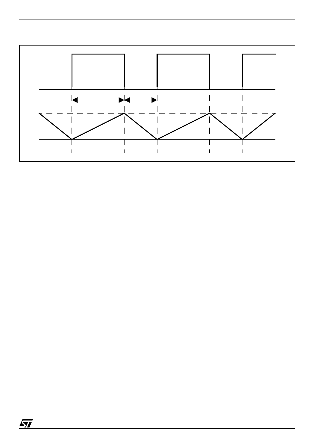
The charge time (output HIGH) is given by
(1) t
= 0.693 (R1 + R2) C
1
1
and the discharge time (output LOW) by
4
NE555
R
1
8
7
R
2
6
C
1
(2) t
= 0.693 (R2) C
2
1
Thus the total period T is given by
(3) T = t
2/7
+ t2 = 0.693 (R1 + 2R2) C
1
2
1
Page 3
A HIGH RESOLUTION / PRECISION THERMOMETER USING ST7 AND NE555
Figure 2. NE555 Timing Diagram
output
t
1
t
2
voltage on
C
1
3 THEORY OF OPERATION - NE555
In general we can use the R
of R
. The times needed to charge (1) and to discharge (2) the capacitor will be
1
(4) t
= 0.693 (R
1
(5) t2 = 0.693 (R2) C
The result of the measurement should be dependent on the value of R
C
should not v ary with tem pera ture or age. That is why the capac itor C1 is to be eliminated
1
from the equations.The peri ods t
and (5) we can calculate two variables.
Expressing C
(6) R
from (5) and putting it in (4) we obtain
1
= R2 (t1-t2) / t
ntc
The result depends on the precision of the time measuring (t1, t2) and tolerance of R2 only. It
depends neither on C
nor the supply voltage.
1
in place of R1 as well as in place of R2. We assume R
ntc
+ R2) C
ntc
1
1
ntc
and t2 are measured with the ST7 ti mer. F rom form ula (4)
1
2
in place
ntc
only. For that R2 and
4 THEORY OF OP ERATION - ST7
The rising and falling edges of the input signal are captured by the micro and periods t1, t2 are
measured with the built-in timer. The timer resolution (125 ns @ 8MHz) is sufficient to capture
these edges.
Note: To c alc ulate equation (6) we can use multiples of 125ns for simplicity.
3/7
Page 4

A HIGH RESOLUTION / PRECISION THERMOMETER USING ST7 AND NE555
5 DESIGN
To design our circuit, we need to choose the right values of R2 and C1. These two values determine the frequency of the output sign al (3).
For the given temperature range (0 - 40 °C) and a 10KΩ NTC resistor, the chosen values are
40kΩ for R
Table 1. Table of theoretical values of designed thermometer
and 100nF for C1.
2
Temperature
(°C)
0 27279 4,662 2,772 37299 22176 635
1 26134 4,583 2,772 36665 22176 605
2 25043 4,507 2,772 36060 22176 577
3 24003 4,435 2,772 35483 22176 549
4 23012 4,367 2,772 34934 22176 524
5 22067 4,301 2,772 34410 22176 500
6 21166 4,239 2,772 33910 22176 477
7 20306 4,179 2,772 33434 22176 455
8 19486 4,122 2,772 32979 22176 434
9 18703 4,068 2,772 32545 22176 414
10 17956 4,016 2,772 32131 22176 395
11 17243 3,967 2,772 31736 22176 378
12 16561 3,920 2,772 31357 22176 361
13 15910 3,875 2,772 30997 22176 345
14 15288 3,831 2,772 30652 22176 329
15 14694 3,790 2,772 30322 22176 315
16 14126 3,751 2,772 30007 22176 302
17 13582 3,713 2,772 29706 22176 288
18 13063 3,677 2,772 29418 22176 276
19 12565 3,643 2,772 29142 22176 263
20 12090 3,610 2,772 28879 22176 252
21 11635 3,578 2,772 28626 22176 242
22 11199 3,548 2,772 28385 22176 231
23 10782 3,519 2,772 28154 22176 222
24 10382 3,491 2,772 27932 22176 212
25 10000 3,465 2,772 27720 22176 203
26 9633 3,440 2,772 27517 22176 195
27 9282 3,415 2,772 27322 22176 187
28 8945 3,392 2,772 27135 22176 179
29 8622 3,370 2,772 26956 22176 172
30 8312 3,348 2,772 26784 22176 164
31 8016 3,328 2,772 26620 22176 158
32 7731 3,308 2,772 26462 22176 151
33 7458 3,289 2,772 26311 22176 146
34 7195 3,271 2,772 26165 22176 139
R
(Ω)t
ntc
(ms) t2 (ms) t1 (tics) t2 (tics)
1
∆t
(tics)
1
4/7
Page 5

A HIGH RESOLUTION / PRECISION THERMOMETER USING ST7 AND NE555
Temperature
(°C)
R
(Ω)t
ntc
(ms) t2 (ms) t1 (tics) t2 (tics)
1
35 6944 3,253 2,772 26026 22176 134
36 6702 3,236 2,772 25892 22176 129
37 6470 3,220 2,772 25763 22176 124
38 6247 3,205 2,772 25639 22176 119
39 6033 3,190 2,772 25521 22176 114
40 5827 3,176 2,772 25406 22176
Table 2. Parameters and their meanings
Parameter Comments
R
(Ω)
ntc
, t2 (ms)
t
1
t
, t2 (tics)
1
(tics)
∆t
1
Value of 10KΩ NTC-Resistor at particular temperature
Example: R
(25 °C) = 10KΩ
ntc
Values of the time corresponding to measured temperature, please refer to equations (4), (5).
Example:
(25°C) = 0.693 * (10 kΩ + 40 kΩ) * 100nF = 3.465 ms
t
1
(25°C) = 0.693 * 40 kΩ * 100nF = 2.772 ms
t
2
Values of the time in 125ns timer tics (@8 MHz)
Example:
t1 (25°C) = 3.465 ms / 125 ns = 27720 tics
(25°C) = 2.772 ms / 125 ns = 22176 tics
t
2
1 tic = Time period of timer
Represents achieved resolution. It's the difference of the values per one degree
Celsius ∆t
= t1(n) - t1(n+1).
1
Example:
(25°C) = t1 (25°C) - t1 (26°C) = 27720 - 27517 = 203 tics
∆t
1
∆t
(tics)
1
6 PRACTICAL ISSUES
It is possible to implement this algorithm with any ST7 family micro (2K of program memory is
required). In general you can choose:
■
12-bit autoreload timer allowing configuration to f
■
16-bit timer allowing configuration to f
(~250ns), for ex. ST72264 @8MH z
cpu/2
In the second case we are able to do the time measuring in one timer cycle.
Averaging of measured results is recomme nded bu t not n eeded. The frequenc y is qui te
stable.
You can use bipolar SA555, SE555 instead of NE555 (the difference is in the operating temperature range only). Recommended values are 40k for R
CMOS TS555 you should redesign the resistor and capacitor values to match its electrical
characteristics.
(~125ns), for ex. ST7LITE @8MHz
cpu
and 100nF for C1. If you use
2
5/7
Page 6

A HIGH RESOLUTION / PRECISION THERMOMETER USING ST7 AND NE555
7 CONCLUSION
With this method we are able to achieve high resolution temperature measurement. The main
advantages are the independence from variations in capacit or C
the precision of the used resistor and the NTC affects the final result.
and the supply voltage. Only
1
6/7
Page 7

A HIGH RESOLUTION / PRECISION THERMOMETER USING ST7 AND NE555
“THE PRESENT NOTE WHICH IS FOR GUIDANCE ONLY AIMS AT PROVIDING CUSTOMERS WITH INFORMATION
REGARDING THE IR PRO DUCT S IN OR DER FO R THEM TO SAV E TIME . AS A RES ULT, STMIC ROEL ECTR ONI CS
SHALL NOT BE HELD LIABLE FOR ANY DIRECT, INDIRECT OR CONSEQUENTIAL DAMAGES WITH RESPECT TO
ANY CLAIMS ARISING FROM THE CONTENT OF SUCH A NOTE AND/OR THE USE MADE BY CUSTOMERS OF
THE INFORMATION CONTAINED HEREIN IN CONNECTION WITH THEIR PRODUCTS.”
Information furnished is believed to be accurate and reliable. However, STMicroelectronics assumes no responsibility for the consequences
of use of such information nor for any infringement of patents or other rights of third parties which may result from its use. No license is granted
by implic ation or oth erwise unde r any patent or patent r i ghts of STMi croelectroni cs. Speci fications me ntioned in this publicat i on are subject
to change without notice. This publication supersedes and replaces all information previously supplied. STMicroelectronics products are not
authorized for use as critical components in life su pport device s or systems without express written approval of STMicroelectronics.
The ST logo is a register ed t rademark of ST M i croelectroni c s.
All other nam es are the pro perty of their respective ow ners
© 2004 STMi croelectroni cs - All rights reserved
STMicroelectron i cs GROUP OF COMPANIES
Australia – Belgium - B razil - Canad a - China – Czech Republic - Finl and - France - Ger many - Hong Kong - India - Israel - Italy - Japan -
Malaysia - Malta - Morocco - Singapore - Spain - Sweden - Switzerland - United Kingdom - United States
www.st.com
7/7
 Loading...