

Page 1

AN1754
APPLICATION NOTE
DATA LOGGING PROGRAM FOR TESTING
ST7 APPLICATIONS VIA IC C
by Microcontroller Division Application Team
INTRODUCTION
Data logging is the process of recording data. It is required during the course of application development in order to test application robustness and reliability.
The purpose of this application note is to show how to implement a data logging system based
1)
on the ICC protocol
Over a specified time period, the data logging system records each and every value of a par-
ticular variable or register used by the application. T he advantage of using this ICC-based
data logging package is that your application runs on the ST7 in its target environment, with
the same hardware configuration and settings and with minimal added software.
An ST7 application software example and the PC side executable are pr ovided with thi s application note. The PC software uses the STVP7
between a PC-based data logging system and the user applic ation. It can be used for ST 7 devices supported by the STICK, i.e. ST7 devices supporting ICC protocol except the U SB family
devices. The ST7 software provided is an example which can be modified and used, or a completely new software may be developed by the user.
.
2)
DLLs for communicating via the ICC Protocol
1)
The ICC protocol (In-Circuit Communication) is used to connect ST7 micro controllers with
an external controller such as a flash programmer or in-circuit debugger. It is described in detail in the ST7 ICC Protocol Reference Manual.
2)
STVP7 (ST7 Visual Programmer) is the Windows software interface for ST7 Flash Programming Tools (S T7 EP B’s a nd ST7 S TIC K). Fo r mo r e inf orma ti on on S T7 Developm ent T ools
refer to http://mcu.st.com.
Rev. 1.0
AN1754/1103 1/19
1
Page 2
DATA LOGGING PROGRAM FOR TESTING ST7 APPLICATIONS VIA ICC
1 SYSTEM HARDWARE AND SOFTWARE REQUIREMENTS
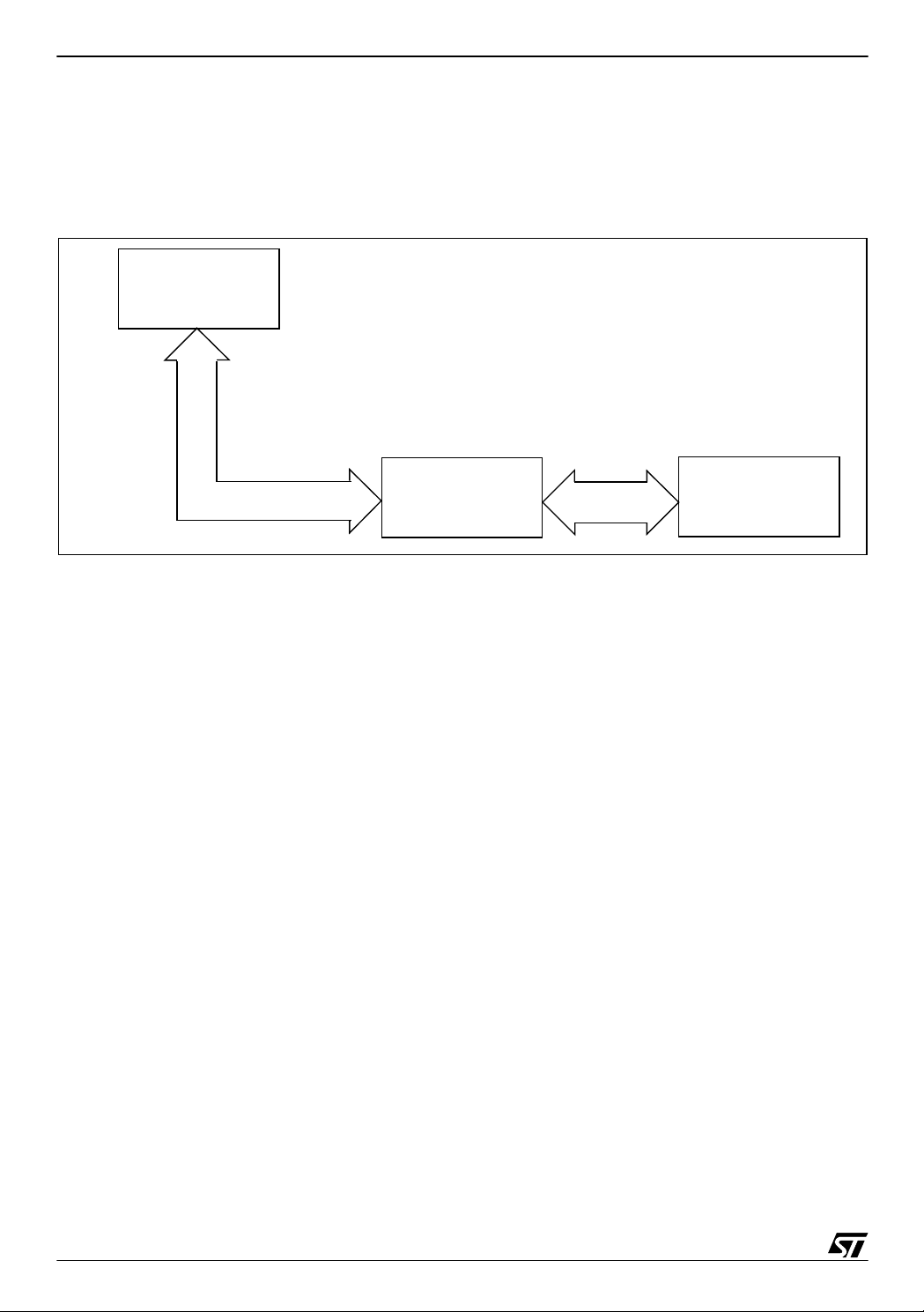
The hardware interfa ce betwe en the para llel port and th e ICC (H E10) co nnector i s the ST7
STICK. A block diagram of the set-up is shown in Figure 1.
Figure 1. Data Loggi ng hardware setup
PC COMPUTER
STVP7 DLL
ST7
APPLICATION
BOARD
PARALLEL PORT
ST7 STICK
(ICC ADAPTER)
ICC(HE10)
INTERFACE
The PC software has been developed using the Microsoft Visual C++ 6.0 environment and the
ST7 software example is compatible with both Cosmic and Metrowerks C c ompilers. The s oftware has been tested with the A/D converter application on the ST7 2F264 a nd ST72 F52 1.
The ICC monitor embedded in the ST72F 264 is the ad vanced variant (it has add itional commands), the ICC monitor em bedded in ST72F521 is the basic variant. The software ex am ple
works with both variants.
The process of data logging developed in this application takes advantage of the fact that
even when th e ST7 is in ICC m ode, it can exec ute the user co de program med in Flash
memory as well as the ICC commands embedded in BootROM/Sysmem.
2/19
2
Page 3

DATA LOGGING PROGRAM FOR TESTING ST7 APPLICATIONS VIA ICC
2 PC SOFTWARE
The software on the PC side has been created in Microsoft Visual C++ 6.0 re-using DLLs from
the STVP 7 soft ware. It can ha ndle all the ST7 d evice s suppo rting IC C prot ocol, e xcept t he
USB family devices. Prior to running the PC software, you must install STVP7 on your PC and
program your device with your application code and the option bytes. The executable for the
PC software has been provided. When you execute this file, you will be prompted for certain
parameters. Section 4 of this applic ation note describes these parameters, two of which determine whether the data logging process is to be performed with the option bytes enabled or disabled. Make sure that the ST7 is driven by the clock source corresponding to this selection.
Please not e that this packag e is comp atible w ith STVP7 1.9.0 an d uses the syste m drivers
corresponding to this version. In case the version of STVP7 installed on your system is a different one, please replace the dll files with the corresponding ones from the STV P7
folder(..\stm\st7toolchain\stvp7).
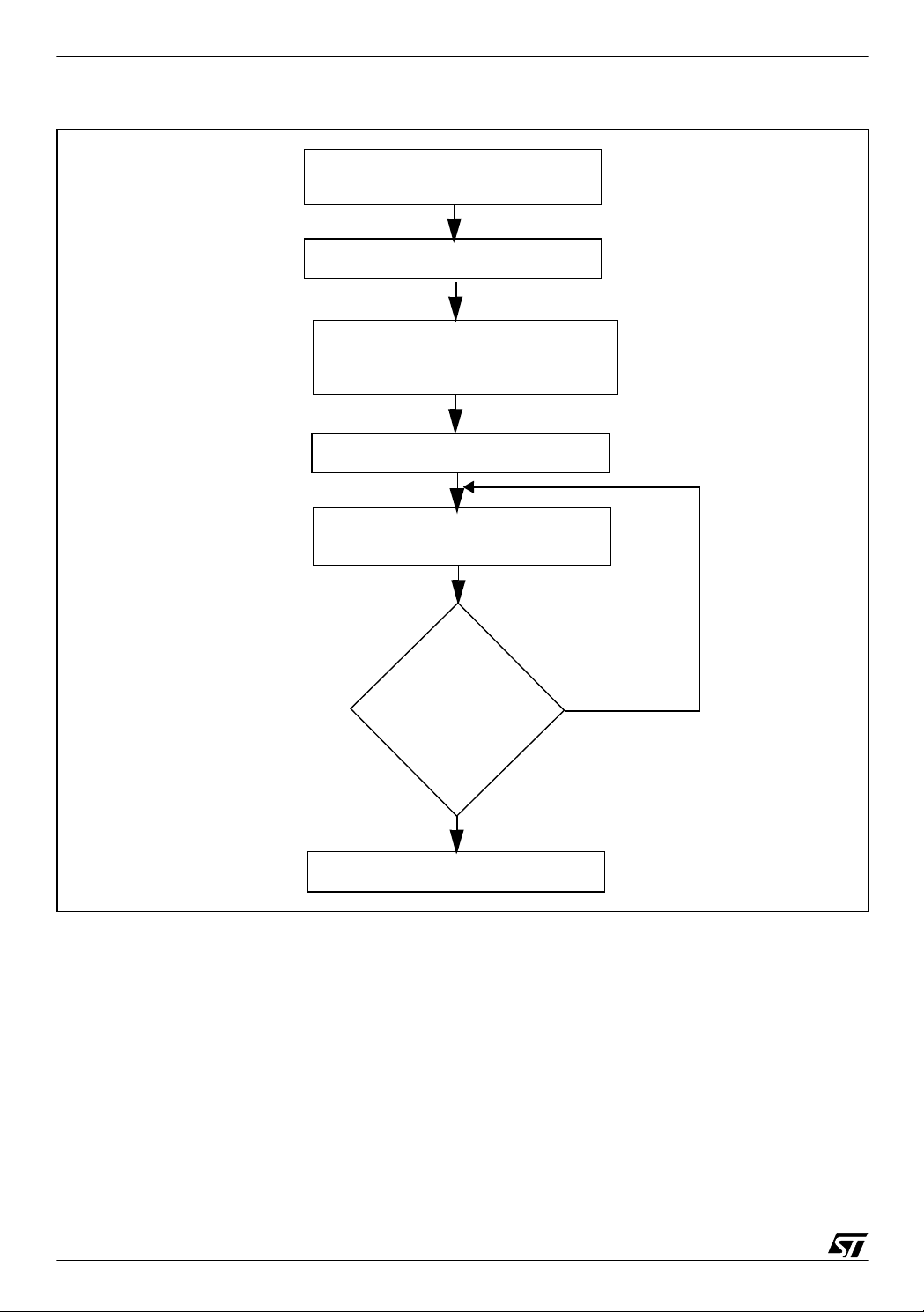
The PC software flowchart is given in Figure 2.
3/19
Page 4
DATA LOGGING PROGRAM FOR TESTING ST7 APPLICATIONS VIA ICC
Figure 2. PC software flowchart
GET USER OPTION BYTE
MODE SELECTION
INITIALIZE PARALLEL PORT
OVERWRIT E PC AT BOTTOM
OF ST7 STACK WITH
APPLICATION START ADDRESS
EXECUTE ICC GO C OMMAND
RECEIVE A BYTE OF DATA
FROM ST7 AND STOR E IN FILE
USER
No
HIT ANY
KEY?
Yes
STOP
After entering ICC mode, the PC softw are mo difies the ST 7 stack s o th at the position c orresponding to the Program Counter contains the address of the user application. Hence, the ex ecution of the Go command has the effect of jumping to the user application and executing it.
The external controller software then loops to receive bytes till the keyboard is hit. The bytes
received are stored in the file “Datafile.doc” in the PC_application folder.
4/19
Page 5

DATA LOGGING PROGRAM FOR TESTING ST7 APPLICATIONS VIA ICC
3 ST7 SOFTWARE
The PC application performs the initialization and starts execution of the ST7 application. At
this point, your ST7 application has to s end the data bytes to the PC. The method you use depends on the variant of the ICC monitor in the ST7 device because some ICC commands are
available only in the medium or extended variant and not in the basic variant. Please refer to
theST7 ICC Protocol Reference manual for the table listing ST7 devices with the ICC monitor
variant embedded in each type.
If the device chosen has a m edium or advanced variant ICC monitor, you can just call the
ICC_Send_Byte routine at the address provided in the ICC Protocol Reference manual. If the
device has a basic ICC monitor, the send byte routine needs to be coded as part of your application. The sample program provided with this application note includes a send byte routine
which you can use.
The software provided can be configured to support devices with any ICC monitor variant.
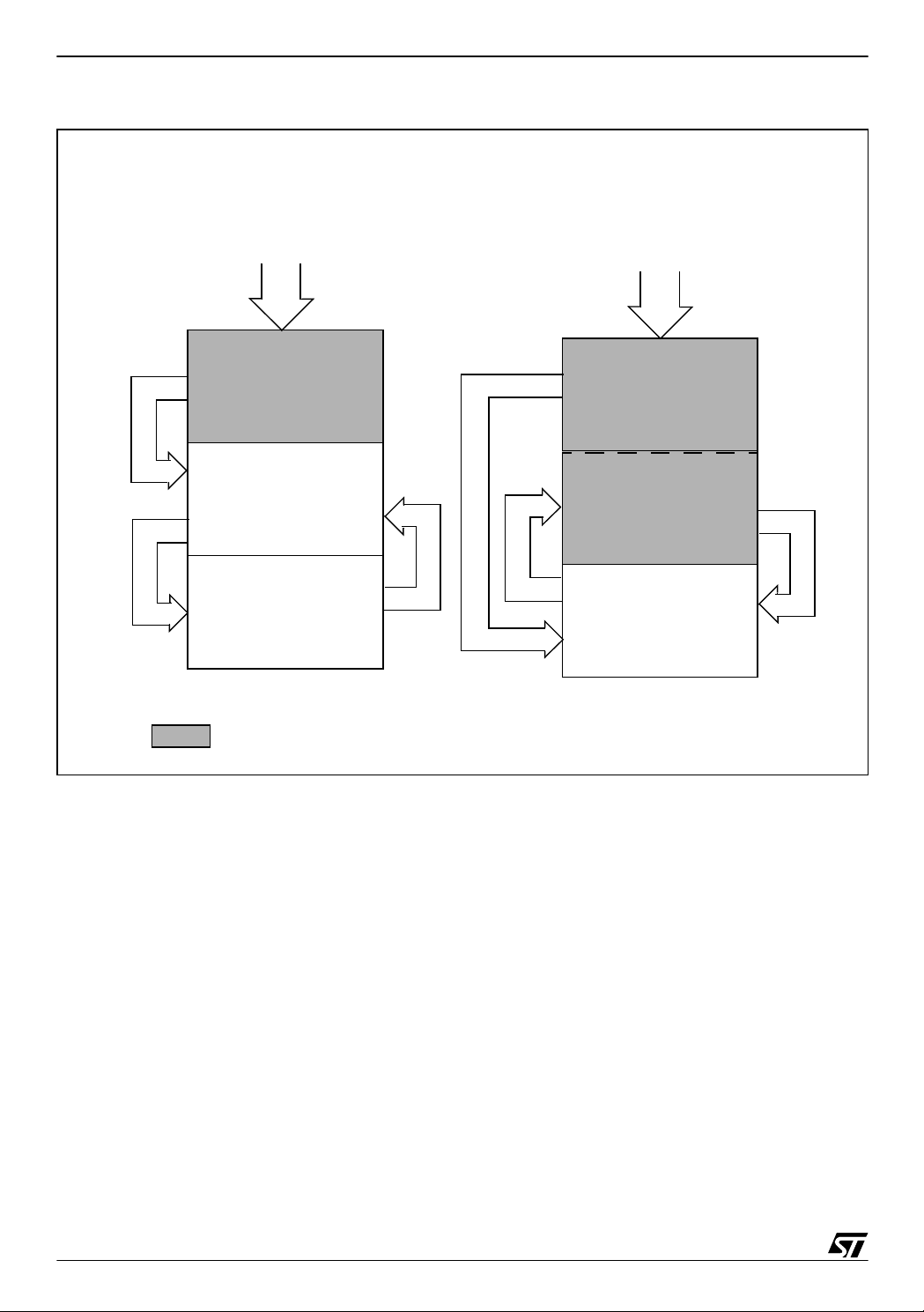
The ST7 software execution is given in Figure 3.
5/19
Page 6
DATA LOGGING PROGRAM FOR TESTING ST7 APPLICATIONS VIA ICC
Figure 3. ST7 Software Execution
Basic ICC Monitor Variant
ICC Mode Entry
Basic ICC Monitor
Go
ST7 Application
Call
ICC SendByte
Routine
Return
Medium/Advanced IC C Monitor Variant
ICC Mode Entry
Medium/Advanced
ICC Monitor
Go
ICC SendByte
Routine
Call
Return
ST7 Application
= ST7 System Memory
Basically, you can run an ST7 application and call the Send byte routine whenever you want
to “note” a particular variable/register. The PC receives the data and stores it in a file named
Datafile.doc whose size is only limited by the amount of PC memory. This method can be used
to store data over long periods of time to be examined and analysed later.
Essentially, the ST7 sof tware i s synchroni zed w ith the ex ternal control ler using th e IC C protocol. Once the user stops the external controller, the device stops sending bytes since it does
not get the desired response from the external controller.
6/19
Page 7

DATA LOGGING PROGRAM FOR TESTING ST7 APPLICATIONS VIA ICC
4 HOW TO USE THE DATA LOGGING SOFTWARE PACKAGE
This section explains the exact changes that you need to make to adapt the package for a
specific ST7 device.
On the PC s ide, you only have to execu te the AP IData log.ex e file. You will be prompte d to
enter certain parameters which are explained in Section 4.1.
On the ST7 side, the parameters to be changed have been grouped into the “main.h” file.
Hence, all changes and selections are to be made in the main.h, unless mentioned othe rwise.These parameters are explained in Section 4.2.
Before you start, you have to install STVP7 and program the ST7 flash with your user application and opt ion by tes. An exam ple u ser applica tion i s pro vided wit h th e pa ckage (use rappli.s19).
4.1 USING THE PC SOFTWARE
When you run APIDatalog.exe, you will be prompted for some inputs. These inputs will set
certain parameters which can be split into two categories:
■ Device specific parameters: These parameters have to be set to the values specified in
the datasheet (Stack top address) and ST7 ICC Protocol Reference manual (Settings for
ICC mode entry). In case of ICC mode entry settings, they also have to match the option byte
settings in the ST7 device, so there is no conflict when the ST7 tries to detect the clock.
■ Application specific parameters: These parameters have to match the application
programmed in the ST7, like the application start address and the timeout parameter.
A detailed explanation of these parameters follows:
4.1.1 Number of Pulses
This input selects the number of pulses to be s ent to the device to enter ICC mode. The
number of pulses us ed to ent er IC C mode determ ines whether th e opt ion byte configu ration
programmed in the device is used or ignored. Hence, this is to be used to select the clock
source of the ST7.
Case 1: User chooses to ignore the option bytes - The ST7 must then be driven by an external clock which in this case, is provided by the STICK. In thi s configurati on, pin 9 of the ICC
(HE10) connector on the application board must be connected to the OSCIN pin of the microcontroller.
Case 2: User chooses to use the option bytes - The clock has to be provided on the application board.
7/19
Page 8

DATA LOGGING PROGRAM FOR TESTING ST7 APPLICATIONS VIA ICC
4.1.2 Enable STICK to provide externa l clock
This input decides whether the STICK ICCOSC buffer is enabled or disabled. If enabled, then
the clock provided by the STICK is available on pin 9 of the ICC(HE10) connector of the
STICK.
4.1.3 User application MSB and LSB
You have to provide the MSB and the LSB of the start address of your user application. These
inputs are used to modify the micro controller stack to jump to the required location in the device Flash memory. They have to be entered in the format: e0 etc. and not 0xe0.
4.1.4 STACK_TOP
You have to enter the stack top address of the micro controller you are usi ng.This input has to
be entered in the format: 17f etc. and not 0x17f.
4.1.5 Timeout in milliseconds
This is an important par ameter w hich ha s to be modified by the user to ens ure s ynchronization. It defines the maximum time that the PC software will wait to receive a byte, before timing
out. Hence, you need to fix this parameter to the maximum time that may elapse between two
consecutive bytes sent by your micro controller application.
The parameters entered by you will be stored in the Parameters.ini file so that you can choose
to set new parameters or use the settings of your last session. The package as provided, has
these parameters set to communicate w ith the ST72F264 device in ICC mode with option
bytes ignored and the user application starting at 0xe000.
8/19
Page 9

DATA LOGGING PROGRAM FOR TESTING ST7 APPLICATIONS VIA ICC
4.2 ADAPTING THE ST7 SOFTWARE
In this package, tested workspaces are provided for implementing a data logging system for
ST72F521 and ST72F264 devices using both Metrowerks and Cosmi c tool chains. The workspaces have bee n named ADC_HIW_5 21, ADC_CSMC_ 521, ADC_HIW_264 a nd
ADC_CSMC_264 according to the combination of device and toolchain supported. All the
workspaces use different toolchain and configuration settings for the same source code. This
source code implements an application running the ADC to perform conversions continuously
and sending back the contents of ADCDRH to the PC.
The ST7_application, as delivered, is configured for the ST72F264 device. In order to migrate
from one device to another, certain changes have to be made. All the following changes are to
be made in main.h, except for the change described in Section 4.2.2.
4.2.1 Compiler path
Please check paths in the configuration files for the compiler being used.
4.2.2 Microcontroller Selection
You have to s elect th e approp riate device in the ST7li b_confi g.h file an d provide the co rresponding peripheral registers and configuration files.
4.2.3 ICC Monitor Variant
The ICC moni tor o n t he S T7 mi cro co ntroller may be a Basic , Me dium or Advanc ed var iant.
The variant of the monitor determines the ICC commands supported by it. The different variants and the ICC commands supported by them are summarized in Table 1 ICC Monitor Variant.
Table 1. ICC Monitor Variant
Name
Write Memory X X X
ICC Command
Automatic Context Saving X
Go X X X
Go New Context X
Read memory X X
Basic Medium Advanced
ICC Monitor Variant
The variant of ICC monitor determines whether you have to provide the ICC Send Byte routine
or not.
Case: Medium or Ad vanced variants - You must update the address of the I CC Send Byte
routine according to the addresses specified in the ICC Protocol Reference manual.
Case: Basic variant - You call a user-programmed Send Byte routine, just like calling any
other user specified function. In this case, you also have to update the ICCPort_xxx register
references and the ICCCLK & ICCDATA pin references accordingly.
9/19
Page 10

DATA LOGGING PROGRAM FOR TESTING ST7 APPLICATIONS VIA ICC
Note: If you u se the Cosmic C Compi ler to generate code for dev ices with medium and ad-
vanced ICC monitor, you h ave to mo dify the ad dress of the send byte routine in the
“DATA_Logging” function in the main.c file of the ST7_application workspace.
4.2.4 Application specific parameters
Finally, if you are using the example ST7 application provided with the package, you have to
change the OutPort_xxx register details and the ANALOG_CHANNEL number before you can
use it.
To use the se nd byte rou tine p rovided with the package , you hav e to assign the data to be
logged to USER_Dat a and call the DATA_Loggi ng function with USE R_Data as the param eter.
The ST7 application provided with this package is only a sample package which supports
ST72F264 and ST72F521 devices. If you want to use a device other than these two, you can
either choose to write the corresponding ST72Fxxx_periph.h, ST72Fxxx_reg.c and
ST72Fxxx_reg.h files or you can make a completely new application. Please note that in case
of devices with bas ic ICC m onitor, you need to pr ovide and call a routine l ike th e Sen d Byte
routine provided in this package.
10/19
Page 11

DATA LOGGING PROGRAM FOR TESTING ST7 APPLICATIONS VIA ICC
5 CONSTRA INTS
5.1 SYSTEM CONSTRAINTS
■ You must not execute STVP7 and APIDatalog.exe at the same time since the DLLs access
common resources.
5.2 DEVICE RESOURCE CONSTRAINTS
■ You must not use the ICCCLK and ICCDATA port pins in your application software.
5.3 TIMING CONSTRAINTS
■ Any data logging system will work, subject to the constraint that the time between two
consecutive data “logs” has to be greater than the time required to c all and execute the send
byte routine.
The execution time of the asm ICC send byte routine as provided in the ICC Protocol
Reference manual is 78 memory cycles and that of the ‘C’ routine provided with this package
is 123 memory cycles. In both cases, the calculated time excludes the time required to call
the function. In case of the ‘C’ routine, it must be noted that thi s is only the execution ti me of
the Send_Byte routine itself which is called by the DATA_Logging Function.
Note: The number of cycles required to execute the routines are given as best case figures,
when the micro controller does not have to loop while waiting for a response from the
external controller, but finds the line released.
■ In the ST7 application provided with this package, the SendByte routine does not time out.
Hence the ST7 device may remain waiting for a few hundred microseconds during WIndows
background activities.
11/19
Page 12

DATA LOGGING PROGRAM FOR TESTING ST7 APPLICATIONS VIA ICC
6 CONCLUSION
The example da ta log ging packag e provided with this application no te is inten ded to be
adapted to a user application for the purpose of receiving and storing bytes on the PC. It is up
to you to modify the example to suit your needs . For i nstance, you can extend it to store 10-bi t
ADC results or to log any number of different variables, with each variable being stored in its
own respective file. The possibilities are numerous.
12/19
Page 13

DATA LOGGING PROGRAM FOR TESTING ST7 APPLICATIONS VIA ICC
7 ST7 SOFTWARE
7.1 MAIN.H
/
********************************* ***********************************
COPYRIGHT 2003 STMicroelectronics
Source File Name : main.h
Group : IPSW,CMG - IPDF
Author : MCD Application Team
Date First Issued: 24/09/2003
***************************Docume ntation****************************
General Purpose - This file is the header of the main module of ST7
software for Data logging. User needs to make certain changes in this
file for device compatibility.
**************************Revisio n History**************************
Date:24/09/2003 Release:1.0
********************************* **********************************/
#include "ST7lib_config.h" /* select appropriate device */
/****Select appropriate monitor according to the device selected****/
//#define BASIC_monitor
//#define MEDIUM_monitor
#define ADVANCED_monitor
/* If selected micro controller ha s medium or adva nced monitor, ICC
send byte routine i s used. Address of the rou tine for differen t devices is provided in the IC C Protocol manual. In case of basic monitor, a routine has to be as part of the user code. */
#ifdef MEDIUM_monitor
13/19
Page 14

DATA LOGGING PROGRAM FOR TESTING ST7 APPLICATIONS VIA ICC
#define Send_Byte 0xDF00; / * ICC_Send_Byte for ST72F264*/
#endif
#ifdef ADVANCED_monitor
#define Send_Byte 0xDF00
#endif
unsigned char USER_Data;/*USER_Data is the data that is being logged*/
/*User has to change the following se ction according to regis ters of
selected device*/
/**************264 register setti ngs*********/
/*Output port to display data bei ng transmitted*/
#define OutputPort_DDR PBDDR
#define OutputPort_OR PBOR
#define OutputPort_DR PBDR
/*To define ICCCLK and ICCDATA in case user defined Send_Byte routine
is used*/
#define ICCCLK 0
#define ICCDATA 1
#define ICCPort_DDR PADDR
#define ICCPort_DR PADR
#define ANALOG_CHANNEL 5
/**************521 register setti ngs*********/
14/19
Page 15

DATA LOGGING PROGRAM FOR TESTING ST7 APPLICATIONS VIA ICC
//#define OutputPort_DR PADR
//#define OutputPort_DDR PADDR
//#define OutputPort_OR PAOR
//#define ICCPort_DR PCDR
//#define ICCPort_DDR PCDDR
//#define ICCCLK 6
//#define ICCDATA 4
//#define ANALOG_CHANNEL 0
7.2 MAIN.C
/*
********************************* ***********************************
COPYRIGHT 2003 STMicroelectronics
Source File Name: main.c
Group : IPSW,CMG-I PDF
Author : MCD Applic ation Team
Date First Issued: 24/09/2003
**************************Documen tation*****************************
General Purpose - This file is the main module of ST7 application for Data
logging.
*************************Revision History***************************
_________________________________ ___________________________________
Date:24/09/2003 Release:1.0
********************************* **********************************/
#include "main.h"
void Configure_output_port(void);
void DATA_Logging(unsigned char);
void Send_Byte_Routine(unsigned char);
void main (void)
15/19
Page 16

DATA LOGGING PROGRAM FOR TESTING ST7 APPLICATIONS VIA ICC
{
int i;
Configure_output_port();
ADC_Init(ADC_DEFAULT); /* Setting ADC at default value */
ADC_Select_Channel(ANALOG_CHA NNEL); /*Select channel for conver-
sion*/
ADC_Enable(); /* Start conversion i.e. ADON bit is set */
while(1)
{
while(ADC_Test_Conversn_Complete() == FALSE);
OutputPort_DR = ADCDRH; /*Display result on port*/
USER_Data = ADCDRH;
DATA_Logging(USER_Data); /*Send data to PC*/
}
}
void Configure_output_port() /*Initializes OutputPort as Output Pushpull*/
{
OutputPort_DDR = 0xff;
OutputPort_OR = 0xff;
}
void DATA_Logging(unsigned char USER_Data)
{
/*In case of basic monitor, user defined send byte routine called*/
#ifdef BASIC_monitor
Send_Byte_Routine(USER_Data);
#else
#ifdef _HIWARE_
#asm
clr A
mul X,A
ld A,USER_Data
call Send_Byte
16/19
Page 17

DATA LOGGING PROGRAM FOR TESTING ST7 APPLICATIONS VIA ICC
send byte address
#endif
}
ret
#endasm
#else
#ifdef _COSMIC_
#asm
clr A
mul X,A
ld A,_USER_Data
call 0xdf00//COSMIC:User has to fill ICC
ret
#endasm
#endif
#endif
void Send_Byte_Routine(unsigned char USER_Data)
{
volatile unsigned char BitCount er = 7;
ICCPort_DDR |= (0x01 << ICCDATA) ; /* ICCDATA made open drain*/
do
{
ICCPort_DR |= (0x01 << ICC DATA); /*Set ICCDATA()*/
if ( !(USER_Data & (0x01 << BitCounter)) ) /* Check for
'0' bit*/
{
ICCPort_DR &= (unsigned char)~ (0x01 << ICCDA-
TA);/* Reset ICCDATA*/
}
/*Wait for 6 clock cycles to ensure IC CDATA level*/
#asm
nop
nop
nop
#endasm
/*Reset ICCCLK since BSET/BRES ICCDATA may affect ICCCLK DR*/
ICCPort_DR &= (unsigned char)~(0x01 << ICCCLK);
ICCPort_DDR |= (0x01 << ICCCLK); /*=> ICCCLK output =
0*/
17/19
Page 18

DATA LOGGING PROGRAM FOR TESTING ST7 APPLICATIONS VIA ICC
/*Wait for 12 clock cycles to ensure ICCDATA level*/
#asm
nop
nop
nop
nop
nop
nop
#endasm
/* Release ICCCLK after 5 Tcpu (ie BRES duration)*/
ICCPort_DDR &= (unsigned char)~(0x01 << ICCCLK);
/*Wait for external contro ller to release IsICCCLK*/
while(!(ICCPort_DR & (0x0 1 << ICCCLK)));
--BitCounter;
}
/* Check if transmission of 8 bits are done */
while(BitCounter<=7);
/*Define ICCDATA as floating in put before returning*/
ICCPort_DDR &= (unsigned char)~ (0x01 << ICCDATA);
}
/****************** (c) 2003 ST Mic roelectronics ********************/
18/19
Page 19

DATA LOGGING PROGRAM FOR TESTING ST7 APPLICATIONS VIA ICC
“THE PRESENT NOTE WHICH IS FOR GUIDANCE ONLY AIMS AT PROVIDING CUSTOMERS WITH INFORMATION
REGARDING THE IR PRO DUCT S IN OR DER FO R THEM TO SAV E TIME . AS A RES ULT, STMIC ROEL ECTR ONI CS
SHALL NOT BE HELD LIABLE FOR ANY DIRECT, INDIRECT OR CONSEQUENTIAL DAMAGES WITH RESPECT TO
ANY CL AIM S AR IS IN G FR OM T HE CO N TENT OF S UC H A NO TE A ND /O R T HE U SE M AD E BY C US TO ME RS O F
THE INFORMATION CONTAINED HEREIN IN CONNECTION WITH THEIR PRODUCTS.”
Information furnished is believed to be accurate and reliable. However, STMicroelectronics assumes no responsibility for the consequences
of use of such information nor for any infringement of patents or other rights of third parties which may result from its use. No license is granted
by implic ation or otherwise under any patent or patent r i ght s of STMi croelectr oni cs. Spec i fications mentioned i n this publication are subject
to change without notice. This publication supersedes and replaces all information previously supplied. STMicroelectronics product s are not
authorized for use as cri tical comp onents in lif e support devi ces or systems without express written approva l of STMicroel ectronics.
The ST logo is a registered trademark of STMicroelectr oni cs.
All other n am es are the property of th ei r respectiv e owners
© 2003 STMi croelectronics - All rights reserved
STMicroelectronics GROUP OF COMPANIES
Australi a – B elgium - Brazil - Canada - China – C zech Republi c - Finland - F rance - Germ any - Hong Kong - India - Is rael - Italy - Japan -
Malaysia - Malta - Morocco - Singapore - Spain - Sweden - Switzerland - United Kingdom - United States
www.st.com
19/19
 Loading...