

Page 1

AN1753
APPLICATION NOTE
SOFTWARE UART USING
ST7 12-BIT AUTORELOAD TIMER
by Microcontroller Division Applications
INTRODUCTION
This application note des cribes a softw are im plementati on of a U niversal As ynchronous Receiver/Transmitter (UART). This can be used on devices, like the ST7LIT E0, with no on- chip
SCI peripheral.
In this example, a software UART is implemented for the ST7FLITE0, using the 12-bit Autoreload timer and two I/O ports for asynchronous receive and transmit. The UART software provides the following features:
• Half-duplex operation
• Asynchronous operation
• Flexible data formats (7 or 8 data bits, 1 or 2 stop bits)
• Baudrate: 2400 to 19200 baud
To test this interrupt-driven software UART, you can use the “Hyperterminal” application run-
ning on a Windows PC.
The program code is quite small (357 bytes) and can easily be adapted to specific application
requirements.
Rev. 1.0
AN1753/1103 1/22
1
Page 2

Table of Contents
INTRODUCTION . . . . . . . . . . . . . . . . . . . . . . . . . . . . . . . . . . . . . . . . . . . . . . . . . . . . . . . 1
1 UART COMMUNICATION . . . . . . . . . . . . . . . . . . . . . . . . . . . . . . . . . . . . . . . . . . . . . . 3
1.1 MAIN FEA TU RES . . . . . . . . . . . . . . . . . . . . . . . . . . . . . . . . . . . . . . . . . . . . . . . . 3
1.2 BAUD RATE . . . . . . . . . . . . . . . . . . . . . . . . . . . . . . . . . . . . . . . . . . . . . . . . . . . . . 3
1.3 FRAME . . . . . . . . . . . . . . . . . . . . . . . . . . . . . . . . . . . . . . . . . . . . . . . . . . . . . . . . . 4
2 RS232 COMMUNICATION WITH A PC . . . . . . . . . . . . . . . . . . . . . . . . . . . . . . . . . . . . 5
2.1 MAIN FEA TU RES . . . . . . . . . . . . . . . . . . . . . . . . . . . . . . . . . . . . . . . . . . . . . . . . 5
2.2 PC CONFIGURATION . . . . . . . . . . . . . . . . . . . . . . . . . . . . . . . . . . . . . . . . . . . . . 5
3 ST7FLITE0 CON FIGURATION . . . . . . . . . . . . . . . . . . . . . . . . . . . . . . . . . . . . . . . . . . 6
3.1 CLOCK SOURCE . . . . . . . . . . . . . . . . . . . . . . . . . . . . . . . . . . . . . . . . . . . . . . . . . 6
3.2 INPUT INITIALIZATION . . . . . . . . . . . . . . . . . . . . . . . . . . . . . . . . . . . . . . . . . . . . 6
3.3 AUTO-RELOAD TIMER REGISTER CONFIGURATION . . . . . . . . . . . . . . . . . . 6
4 UART IMPLEM ENTATION . . . . . . . . . . . . . . . . . . . . . . . . . . . . . . . . . . . . . . . . . . . . . . 8
4.1 BAUD RATE DEFINITION . . . . . . . . . . . . . . . . . . . . . . . . . . . . . . . . . . . . . . . . . . 8
4.2 MAJORITY VOTING SYSTEM . . . . . . . . . . . . . . . . . . . . . . . . . . . . . . . . . . . . . . . 9
4.3 STATUS HANDLING . . . . . . . . . . . . . . . . . . . . . . . . . . . . . . . . . . . . . . . . . . . . . . 9
4.4 TRANSM IT & RECEIVE IMPLEMENTATION . . . . . . . . . . . . . . . . . . . . . . . . . . 10
5 HARDWARE SETUP . . . . . . . . . . . . . . . . . . . . . . . . . . . . . . . . . . . . . . . . . . . . . . . . . 11
6 FUNCTIONAL SOFTWARE FLOW . . . . . . . . . . . . . . . . . . . . . . . . . . . . . . . . . . . . . . 12
6.1 MAIN SOFT W ARE ROUTINES . . . . . . . . . . . . . . . . . . . . . . . . . . . . . . . . . . . . . 12
6.2 SOFTWAR E FLOW CHARTS . . . . . . . . . . . . . . . . . . . . . . . . . . . . . . . . . . . . . . 13
7 TEST PROCEDURE . . . . . . . . . . . . . . . . . . . . . . . . . . . . . . . . . . . . . . . . . . . . . . . . . . 20
8 SOFTWARE . . . . . . . . . . . . . . . . . . . . . . . . . . . . . . . . . . . . . . . . . . . . . . . . . . . . . . . . 21
2/22
1
22
Page 3
SOFTWARE UART USING ST7 12-BIT AUTORELOAD TIMER
1 UART COMM UNICATION
The main features of a standard UART are summarized below.
1.1 MAIN FEATURES
The UART offers a flexible means of full-duplex data exchange
with external equipment requiring an industry standard NRZ asynchronous serial data format.
The UART allows a very wide range of baud r ates and different baud rates for transmission
and
reception.
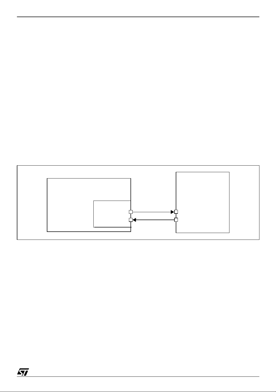
In UART communication, a minimum of only two signals are needed, one for transmission and
other for reception. No clock signal is needed as it works in asynchronous mode. Each device
has to hav e a Transm it Data Ou tput pin (the PA3 pin is used in o ur example for the
ST7FLITE0) and a Receive Data Input pin (PA7 pin in our example). (Refer to Figure 1.)
Figure 1. ST7 UART Communication Set-Up
ST7 System
Terminal
Device
(Host)
ST7FLITE0
(TDO) PA3
(RDI) PA7
You must be very careful to identify the use of each pin. A simple method is to put the device
in transmission and check with an oscilloscope if a transmission frame is present or not.
1.2 BAUD RATE
Transmission and r eception can be driven by their own baud rate generator. However be
aware that for correct communication, the receiver must have a reception baud rate strictly
equal to the transmission baud rate of the transmitter. If not, the communication will be cor-
rupted. A s long as this condition is met, a wide range of baud rates is possible.
RDI
TDO
3/22
2
Page 4
SOFTWARE UART USING ST7 12-BIT AUTORELOAD TIMER
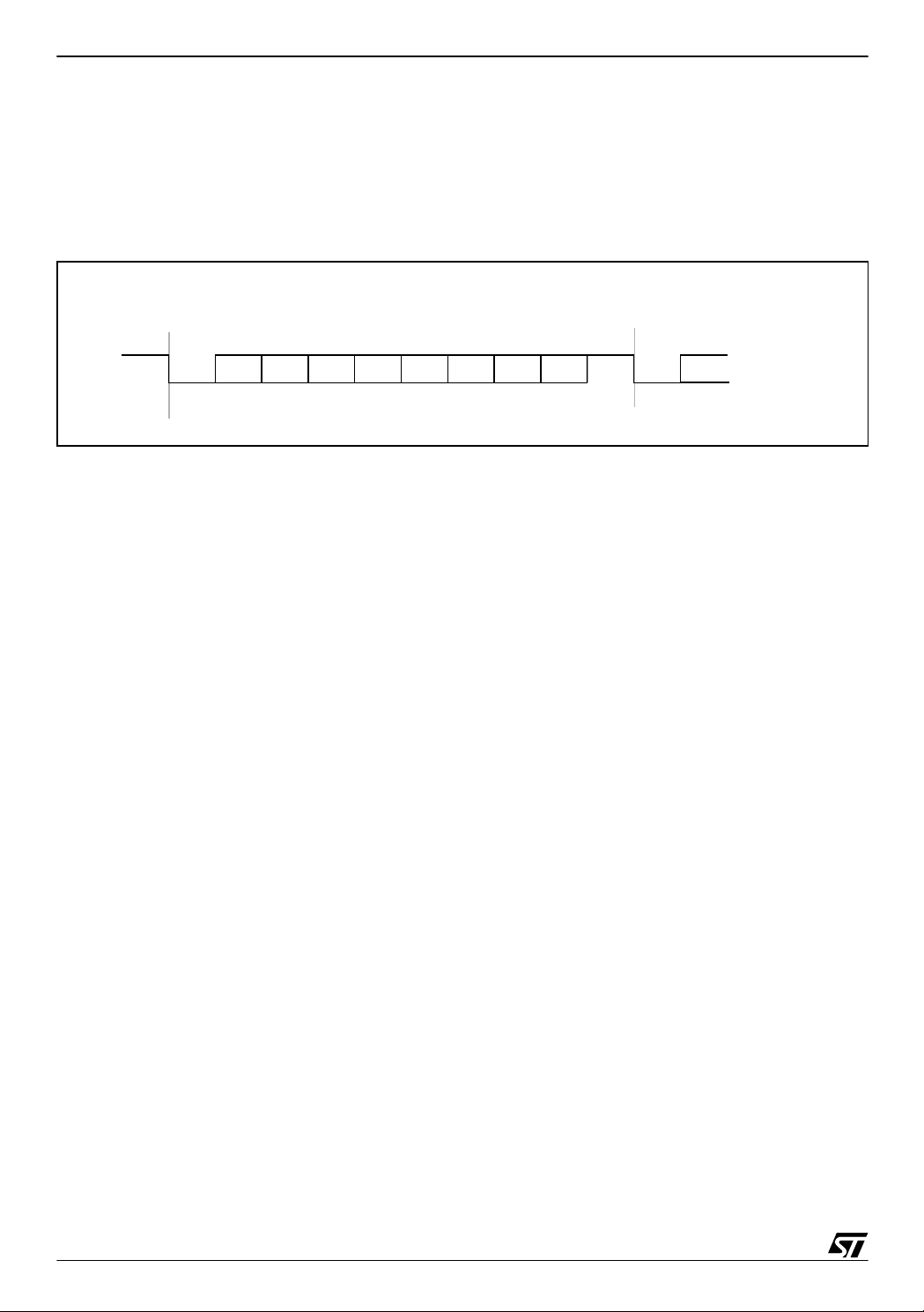
1.3 FRAME
Any transmission is Least Significant Bit first. A data word is us ually 8 bi ts long. A data frame
begins with a «star t bit», which i s a ‘0‘ bit and ends wit h a «stop bit», wh ich is a ‘1‘ bit. See
Figure 2.
Figure 2. Frames
8-bit Wo rd l ength
Next Data Frame
Data Frame
Start
Bit
Bit0 Bit1
Bit2
Bit3 Bit4
Bit5 Bit6
Bit7
Stop
Bit
Next
Start
Bit
In some cases, a 9th bit can be used, as a parity bit or as a second stop bit.
4/22
Page 5

SOFTWARE UART USING ST7 12-BIT AUTORELOAD TIMER
2 RS232 COMMUNICATION WITH A PC
2.1 MAIN FEATURES
Electrical and protocol characteristics of R S232 are different from those used by the UART. In
RS232 communication, high level is typically +7V and low level is typically -7V, while the ST7
I/Os work at CMO S levels (0, +5V).
Furthermore, the polarities are different. A ‘1‘ bit coming from the UART corr esponds to a ‘0‘
bit
in RS232, and a ‘0‘ bit to a ‘1‘ bit. It is true for all bits including the START and STOP bits. So
it is necessary to implement a conversion between the PC and the ST7. In the appl ication, a
MAX232 is used for this purpose.
2.2 PC CONFIGURATION
The PC will be used as a terminal interface. “Hyperteminal”, the terminal application software
is used as a interfacing software to test the functionality [.zip file attached]. The test environ-
ment is Windows 2000.
Under Windows , open the Hy pertermin al applicatio n. To configur e it, go to the port s ettings
and set the parameters to your application requirements. The options in this window must be
the same as the ones defined for your ST7FLITE0, communication device, except the port.
After selecting the right serial commun ication port, select the same baud rate as t he one set
for the ST7. As the PC accepts only one baud rate, transmission and reception baud rates will
have the same value. Data word can be 8/7 bits, but y ou can choos e to use 1 or 2 s top bits.
«Flow control» can be either Xon/Xoff or none. The PC is then correctly configured.
5/22
Page 6

SOFTWARE UART USING ST7 12-BIT AUTORELOAD TIMER
3 ST7FLITE0 CONFIGURATION
3.1 CLOCK SOURCE
This application is implemented using ST7FLITE0 device with an 8 MHz internal clock. PLL *
8 is used to generate this 8 MHz clock.
3.2 INP UT INITIALIZATION
Two pins of the ST7FLITE0 are used:
- PA3: Pin of PortA
- PA7: Pin of PortA with interrupt
Pin PA3 is normal Input/Output port pin with no alternate function, used for transm ission.
During initialization it is configured as an output.
Pin PA7 is normal Input/Output port pin with no alternate function, used for data receive.
During initialization it is configured as an input. While in receive mode, at start, same pin is
used with interrupt enabled (“ei1”) to sense “START” bit. So this pin is configured with “pull up
interrupt input” by setting PADDR to 0 & PAOR to 1. And to set interrupt sensitivity “Falling
edge only” we set IS11=1 & IS10=0 in the EICR register.
Refer to the device datasheet for detailed description of the I/O and interrupt control registers .
3.3 AUTO-RELOAD TIMER REGISTER CONFIGURATION
The AT timer is based on free running 12-bit up counter with 12-bit auto reload register (ATR).
Apart from this it also includes other functionality like, PWM s ignal generator & Output Compare Function & etc.
We are using “Output Compare” functionality for this application. To use this function, the OE
bit must be 0, otherwise the compare is done with the shadow register instead of the DCRx
register. Software must then write a 12-bit value in the DCR0H and DCR0L registers. W hen
the 12-bit upcount er (CNTR) re aches the value s tored in th e DCR0H and DCR0L reg isters,
the CMPF 0 bit in th e PWM0 CSR register is set and an interrup t req uest is gen erated if the
CMPIE bit is set.
6/22
Page 7
SOFTWARE UART USING ST7 12-BIT AUTORELOAD TIMER
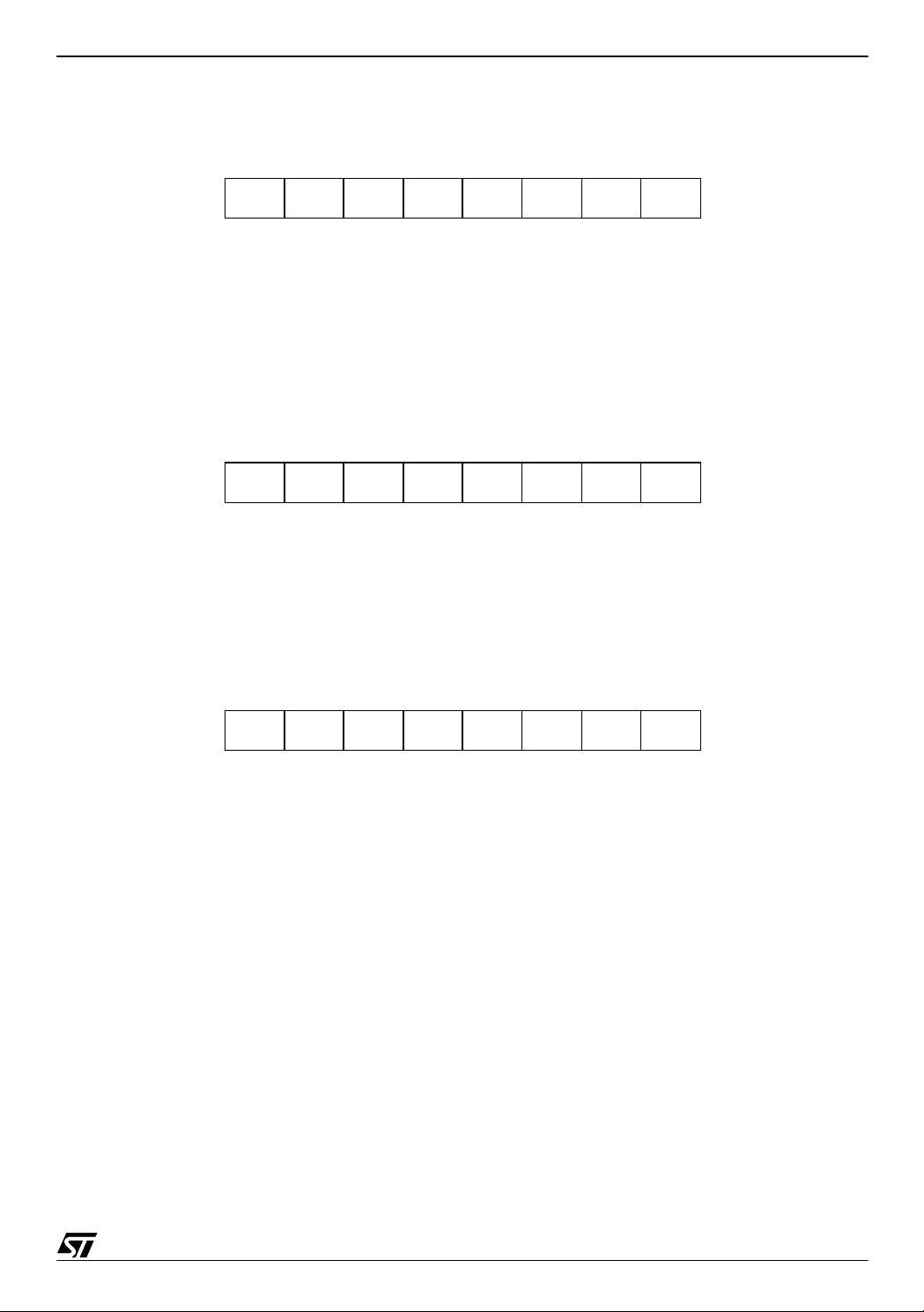
The registers that are used in application note are:
TIMER CONTROL STAT US RE GISTER (ATCSR):
CMPIEOVFIEOVFCK0CK1000
- CK1 & CK0: They select the clock frequency of the counter.
For fcounter = fcpu, set CK1=1 & CK0= 0,
- CMPIE: It allows to mask the interrupt generation when CMPF bit is set.
When it is 0: CMPF interrupt disabled
1: CMPF interrupt enabled
PWM0 CONTROL/STATUS REGISTER ( PWM0CSR):
0000 OP0
0
CMPF00
- CMPF0:
It indicates that the upcounter value matches the DCR register value. When it is,
0: Upcounter value does not match DCR value.
1: Upcounter value matches DCR value.
PWM OUTPUT CONTROL REGISTER (PWMCR):
000
0
0
00
OE0
- OE0: When set to 1, PWM0 output enabled
Timer Initialization:
Write to DCRx registers with required value. Then Output Compare functionality must be enabled. To do this, reset the OE bit in the PWMCR register. This will disable PWM output.
To configure fcounter = fcpu, set CK1=1 & CK0=0, and to enable the CMPF interrupt, set
CMPIE=1 in the ATCSR register.
7/22
Page 8

SOFTWARE UART USING ST7 12-BIT AUTORELOAD TIMER
4 UART IMPL EMENTATION
4.1 BAUD RATE DEFINITION
The Autoreload timer is used to generate the baud rate. Autoreload timer clock (fCOUNTER)
is same as fcpu clock, which is 8 MHz internal clock.
The description here below is the example to show how this baud is generated:
Example:
- baudrate = 2400
- fcpu = 8MHz (so clock period is 125 ns)
- In the application fCOUNTER = fcpu
So to get 2400 baud the “Prescaler” required is,
Prescaler = fcpu / baud
6
Prescaler = 8 * 10
= 0.0033333333 * 10
/ 2400
6
= 3333.33 decimal
= D05 Hex (= 1 bit delay count)
So in software DCRx will be
DCR0H = 0D + CNTRH
DCR0L = 05 + CNTRL
to generate one bit delay when 2400 baud is required
For half bit period “Prescaler” is,
Prescaler = one bit / 2
= 1666.66 (decimal)
= 682 Hex (= 1/2 bit delay)
DCR0H = 06 + CNTRH
DCR0L = 82 + CNTRL
The software provided with this application note has been functionally tested in the range
2400 to 19200 baud.
8/22
Page 9

SOFTWARE UART USING ST7 12-BIT AUTORELOAD TIMER
4.2 MAJORITY VOTI NG SYSTEM
The receive section is complex compared to the transmit section. So, to avoid possible errors
in detecting exact bit status because of line noise etc, this program uses a majority-voting
system. When the ST7 is in receive mode, i t reads (samples) each bit three times at the
middle of the bit time. To determine its exact state, it compares the number of 1’s with the
number of 0’s. If there are more ‘1‘s than ‘0‘s, the bi t received is a ‘1‘, else it is a ‘0‘. ( see Figure
3.)
Figure 3. Majority voting system
START
1st sample
012 3
3rd sample
2nd sample
4
5
67
STOP
This section is only used for the receive part. You can change it to suit your requirements.
4.3 STATUS HANDLING
To keep track of status during program execution, software uses variable, “sci_status”.
Bits 0-4 of this variable are used to hold the system status.
SPBRREBSTE
Definition of each flag:
SP: Reception mode sampling phase
BR: Byte Received flag
RE: Reception Enable
BS: Byte Sent flag
TE: Transmission Enable
9/22
Page 10

SOFTWARE UART USING ST7 12-BIT AUTORELOAD TIMER
4.4 TRANSMIT & RECEIVE IMPLEMENTATION
Transmission mode gets executed after power on. To transmit data, the program uses port pin
PA3 in output mode with “Output Compare” interrupt. One bit is transmitted during each interrupt, generated after a bit delay when the 12-bit upcounter (CNTR) reaches the value (=1 bit
delay) stored in the DCR0H and DCR0L registers. The value for duty cycle resister (DCR0L/
DCR0H) depends on the required baud rate & clock frequency.
For receive mode, the program uses port pin PA7 in input mode along with its interrupt &
output compare f unctionality. To s ense STA RT bit, interr upt “ei1” is used, configured a s
“Falling edge only”. In this interrupt routine, program sets the ATR - output compare value for
half* bit delay & di sable “ei1” interrupt to use PA7 in nor mal input mode to receive enti re frame.
This half bit dela y is used to sa mple bit at m iddle of bit. After r eceiving START bi t in output
compare interrupt, the same interrupt routine gets executed each time a bit must be received.
To receive each bit correctly majority voting system is implemented in this interrupt routine.
The interrupt strategy used in software for transmit & receive allows to have other applications
to work at the same time.
Note:
– Error handling: This program does not handle communication errors (e.g. Frame Errors).
– No handshaking is implemented.
– For better performance at high baud rates it is r ecommended to use character transmission
rather than string transmission.
*User can adjust this value depending on baud rate.
10/22
Page 11

SOFTWARE UART USING ST7 12-BIT AUTORELOAD TIMER
5 HARDWARE SETUP
A general system configuration is shown in Figure 1. The ST7FLITE0 is connected to an RS232 line driver chip which is in turn connected to any RS-232-compatible device. The RS-232
line driver is needed to convert t he 5-volt logic le vel of th e ST7FLITE 0 to the proper R S-232
line voltages, and vice versa.
Figure 4. shows a specific e xample of a hardware s etup required for UA RT in which the
ST7FLITE0 processor and RS-232 Driver/ Receiver are used. You can use different driver/receiver in your application. For example you can use a MC14C88/ 89 as a low cost solution.
The Receive Data pin (RD) of the serial port of the PC mu st correspond to the PA3 pin of the
ST7FLITE0, and the Transmit Data pin (TD) to PA7 pin.
Be sure that the th ree main de vices ( PC, ST7, MA X232 ) have the sam e elec trical refe rence
(GND). For a detailed description of MAX232, please refer to the datasheet.
Figure 4. Test Setup
TERMINAL
PC
seri al port
GND
TD
RD
GROU ND
GND
OUTIN
OUT
MAX232
ST7FLITE0
GND
PA7 pin
IN
PA3 pin
11/22
Page 12

SOFTWARE UART USING ST7 12-BIT AUTORELOAD TIMER
6 FUNCTIONAL SOFTWARE FLOW
The character format used is “ASCII”. Before starting communication you should configure the
communication parameters to your requirements. You can select the baudrate, number of bits
and STO P b its in d iffe r en t c omb i nati ons. H ow e ver , for co r rec t c om mun i cati on , th e r ecei ver
must have a reception baud rate strictly equal to the transmission
baud rate of the transmitter. If not, the communication will be corrupted. So you have to con
figure “Hyperterminal” correctly.
To configur e th e dev ice , you m us t se t d el_1b h, del_1 bl , del _sam pl, d el_sa mp h, STO P_BIT
and TxRx_data_lnth correctly in your software.
After power on, the ST7FLITE0 goes in to transmit mode. It initiates com munication by transmitting character “$” in ASCII format & then goes into receive mode. The PC then receives this
character on its serial port, which can be viewed in the Hyperterminal window.
Now you have to press a key (charac ter) to trans mit. After pressing a c haracte r key, it gets
transmitted and the ST7 receives it. The ST7 then s ends same received c haracter to PC. This
sequence can be repeated continuously (Refer to the flow charts below).
6.1 MAIN SOFTWARE ROUTINES
The UART software consists of main 4 routines:
– Tx_data
– Rx_data
– EI1_Interrupt
– OPCOMP_int
– Tx_data: This routine is used to transmit data in bit format stored in variable “TX_byte”. It
also takes care of synchronization & the output compare interrupt. The AT timer is initialized
to the application configuration inside this routine.
– Rx_data: This routine is used to receive data on the input pin in bit format & stores it in
“RX_byte”. To detect a “START” bit it initializes the PA7 pin in interrupt mode.
– EI1_Interrupt: This “ei1” interrupt routine gets executed only once during receive data when
PA7 receives a “START” (High to Low edge) bit. It also initiates the AT timer for half bit duration.
– OPCOMP_int: This routine gets executed in both transmit & receive mode. During
Tx_dataroutine execution this gets executed for each data bit transfer. And it is actually used
to transmit data on the TxD (PA3) pin along with START & STOP bits.
During receive mode it gets executed for each data bit received including the START & STOP
bits.
The majority-voting system is implemented in the same section of code.
12/22
Page 13

SOFTWARE UART USING ST7 12-BIT AUTORELOAD TIMER
6.2 SOFTWARE FLOW CHARTS
The flowcharts below represent the application program flow.
Figure 5. Main Flowchart
MAIN
Initialize port & variables
Initiate Transmission
RX_data
tx_byte = rx_byte
TX_data
13/22
Page 14

SOFTWARE UART USING ST7 12-BIT AUTORELOAD TIMER
Figure 6. Output Compare Interrupt
t
OPCOMP_int
Init DCRx with CNTRx
Go on “Transmit routine”
Is it 1st. bit?
no
yes
Transmit/Receive
Go on “Receive routine”
14/22
Page 15

Figure 7. Transmit routine
SOFTWARE UART USING ST7 12-BIT AUTORELOAD TIMER
TX_data
Set “TE” flag
Set synchronization
delay
Set clock & enable output compare interrupt
RIM
“BS” flag set
?
yes
SIM
ret
no
15/22
Page 16

SOFTWARE UART USING ST7 12-BIT AUTORELOAD TIMER
Figure 8. Receive data routine
RX_data
Set “RE” flag
Init required variable
Put “RxD” in input interrupt mode. Set EICR reg.
RIM
“BR” flag set
?
yes
SIM
ret
no
16/22
Page 17

SOFTWARE UART USING ST7 12-BIT AUTORELOAD TIMER
Figure 9. Output Compare Tran smit flow
Transmit routine
Set “BS” flag in
“sci_status” var.
Disable interrupt & stop
timer clock
b
bit_count=
“0”
?
no
yes
”FRAME”
sent?
no
All “data”
sent ?
no
Transmit “data” bit
Load “CNTR” with 1 bit
delay count
yes
Send “START” bit
a
yes
Send “STOP”bit
a
Clear prev. interrupt &
set compare interrupt
iret
b
17/22
Page 18

SOFTWARE UART USING ST7 12-BIT AUTORELOAD TIMER
Figure 10. Output Compare Receive Flow
Receive routine
Read & Check for
“STOP” bit condition
Full“frame”
Received?
no
Read “RxD” & apply
majority voting system
Need
“START”
?
no
yes
Need
“STOP” ?
no
Store received data
yes
yes
c
Read & Check for
“START” bit condition
a
c
18/22
Set “BR” flag
Disable interrupt & stop
timer clock
b
a
Page 19

SOFTWARE UART USING ST7 12-BIT AUTORELOAD TIMER
Figure 11. EI1 Interrupt rout ine
EI1_int
Read CNTRx
Set DCRx for 0.5 bit
delay
Set “SP” flag & put “RxD”
in normal input mode
Clear pending interrupt
Enable output compare
interrupt & select clock
iret
19/22
Page 20

SOFTWARE UART USING ST7 12-BIT AUTORELOAD TIMER
7 TEST PROCEDURE
– Connect both the communication & terminal equipment as shown in fig.4
– Open & configure “Hyperterminal “application [Port, Baud rate & etc.].
– Power on ST7
– On the terminal you should get “$” as a starting character (If not then check link between
terminal and the ST7 and check the communication settings)
– Then press a key to send a character
– The same character should be returned by the ST7 (check “Hyperterminal” window)
– Continue by repeating the previous two steps
20/22
Page 21

SOFTWARE UART USING ST7 12-BIT AUTORELOAD TIMER
8 SOFTWARE
The complete software can be found on the ST internet webs ite in zipped file format. It is intended for use only as an example. It is up to you to adapt it to your specific application.
The source file is for guidance only. STMicroelectronics shall not be held liable for any direct,
indirect or consequential damages with respect to any claims arising from use of this software.
21/22
Page 22

SOFTWARE UART USING ST7 12-BIT AUTORELOAD TIMER
“THE PRESENT NOTE WHICH IS FOR GUIDANCE ONLY AIMS AT PROVIDING CUSTOMERS WITH INFORMATION
REGARDING THE IR PRO DUCT S IN OR DER FO R THEM TO SAV E TIME . AS A RES ULT, STMIC ROEL ECTR ONI CS
SHALL NOT BE HELD LIABLE FOR ANY DIRECT, INDIRECT OR CONSEQUENTIAL DAMAGES WITH RESPECT TO
ANY CL AIM S AR IS IN G FR OM T HE CO N TENT OF S UC H A NO TE A ND /O R T HE U SE M AD E BY C US TO ME RS O F
THE INFORMATION CONTAINED HEREIN IN CONNECTION WITH THEIR PRODUCTS.”
Information furnished is believed to be accurate and reliable. However, STMicroelectronics assumes no responsibility for the consequences
of use of such information nor for any infringement of patents or other rights of third parties which may result from its use. No license is granted
by implic ation or otherwise under any patent or patent ri ghts of STM i croelectr oni cs. Spec i fications mentioned i n this publication are subje ct
to change without notice. This publication supersedes and replaces all information previously supplied. STMicroelectronics products are not
authorized for use as cri tical comp onents in life support dev i ces or systems wi thout exp res s written ap proval of STMi croelectr onics.
The ST logo is a registered trademark of STMicroelectr oni cs.
All other n am es are the pro perty of thei r respectiv e owners
© 2003 STMi croelectronics - All rights reserved
STMicroelectronics GROUP OF COMPANIES
Australi a – B elgium - Brazil - Canada - China – Czech Republ i c - Finland - F rance - Germany - Hong Kong - India - Is rael - Italy - Japan -
Malaysia - Malta - Morocco - Singapore - Spain - Sweden - Switzerland - United Kingdom - United States
www.st.com
22/22
 Loading...