

Page 1

AN1752
APPLICATION NOTE
ST72324 QUICK REFERENCE NOTE
by Microcontroller Division Applications
INTRODUCTION
The purpose of this document is to give you a basic understanding of the ST72324 and to help
you quickly get started with developing your application.
It also highlights important aspects of the ST72324 that you should not overlook when reading
the datasheet.
Section 1 gives an overview of the key benefits of the device.
Sections 2 and 3 contain hel pful pointer s to hel p you c hoose the r ight tool for the dev elopment
environment and start working with ST72324.
In each secti on of this ap plic ation note , you w ill fi nd ma ny use ful te chni cal t ips to he lp yo u
make the most of the ST72324 features in your design.
Rev. 1.1
AN1752/1103 1/14
1
Page 2

Table of Contents
INTRODUCTION . . . . . . . . . . . . . . . . . . . . . . . . . . . . . . . . . . . . . . . . . . . . . . . . . . . . . . . 1
1 OVERVIEW OF DEVICE FEAT URES . . . . . . . . . . . . . . . . . . . . . . . . . . . . . . . . . . . . . 3
2 ST72324 KEY BENEFITS . . . . . . . . . . . . . . . . . . . . . . . . . . . . . . . . . . . . . . . . . . . . . . . 4
2.1 8-BIT SOLUTION FOR MID-RANGE APPLICATIONS . . . . . . . . . . . . . . . . . . . . 4
2.2 ENHANCED CLOCK MANAGEMENT MODULE . . . . . . . . . . . . . . . . . . . . . . . . 4
2.3 INTEGRATED FEAT URES FOR MORE RELIABILIT Y . . . . . . . . . . . . . . . . . . . . 5
2.4 NESTED INTERRUPTS . . . . . . . . . . . . . . . . . . . . . . . . . . . . . . . . . . . . . . . . . . . . 5
2.5 POWERFUL INDUSTRY STANDARD COMMUNICATION INTERFACES . . . . 6
2.6 IN-CIRCUIT PROGRAMMING AND IN-APPLICATION PROGRAMMING . . . . . 6
3 ST72324 DEVELOPMENT TOOLS . . . . . . . . . . . . . . . . . . . . . . . . . . . . . . . . . . . . . . . 8
3.1 CO DE DEVELOPMEN T TOOLS . . . . . . . . . . . . . . . . . . . . . . . . . . . . . . . . . . . . . 9
3.1.1 ST7 Assembl e r and Linker . . . . . . . . . . . . . . . . . . . . . . . . . . . . . . . . . . . . . 9
3.1.2 C Compiler toolchains from C o sm ic and Metrowerks . . . . . . . . . . . . . . . . . 9
3.1.3 ST7 Software Library: ST7LIB . . . . . . . . . . . . . . . . . . . . . . . . . . . . . . . . . . . 9
3.2 DEBUGGING TOOL S . . . . . . . . . . . . . . . . . . . . . . . . . . . . . . . . . . . . . . . . . . . . 10
3.2.1 ST7 Visual Debug IDE: STVD7 . . . . . . . . . . . . . . . . . . . . . . . . . . . . . . . . . 10
3.2.2 ST7 Simulator . . . . . . . . . . . . . . . . . . . . . . . . . . . . . . . . . . . . . . . . . . . . . . 10
3.2.3 Emulators . . . . . . . . . . . . . . . . . . . . . . . . . . . . . . . . . . . . . . . . . . . . . . . . . . 10
3.3 PROGRAMMING TOOLS . . . . . . . . . . . . . . . . . . . . . . . . . . . . . . . . . . . . . . . . . 11
3.3.1 ST7 Visual Programmer : STVP7 . . . . . . . . . . . . . . . . . . . . . . . . . . . . . . . . 11
3.3.2 ST7 Programming Board: ST7M DT20J-EPB /EU/US/UK . . . . . . . . . . . . . 11
3.3.3 ST7-STICK . . . . . . . . . . . . . . . . . . . . . . . . . . . . . . . . . . . . . . . . . . . . . . . . 11
3.3.4 ST7 Flash Programmer . . . . . . . . . . . . . . . . . . . . . . . . . . . . . . . . . . . . . . . 12
4 E-SUPPORT . . . . . . . . . . . . . . . . . . . . . . . . . . . . . . . . . . . . . . . . . . . . . . . . . . . . . . . . 13
14
2/14
1
Page 3
ST72324 QUICK REFER EN CE NOTE
1 OVERVIEW OF DEVICE FEATURES
ST72324 family extends the ST7 mid-range for appliance, industrial and automotive applications, requiring medium and large memory capacities and up to 32 I/O ports. The device has
software LIN compatibility and supports extended temperature range (-40°C to +125°C),
which are key features for supporting automotive applications.
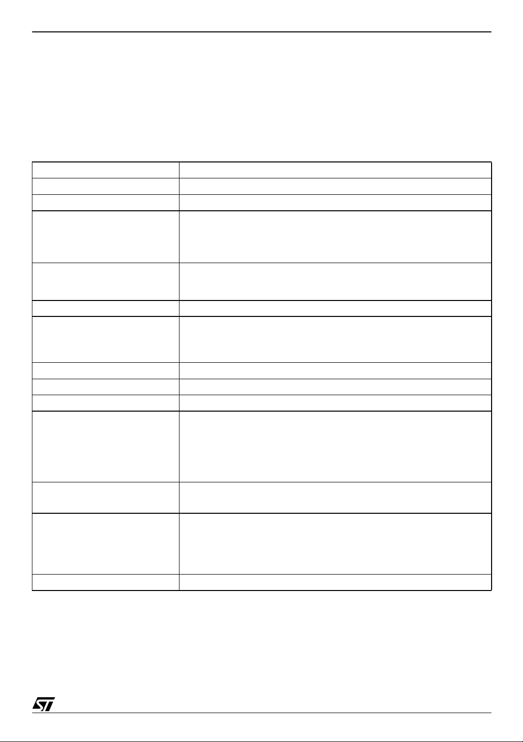
Table 1. Device features
Program Memory 8 to 32k dual voltage Flash or ROM with Read-out protection capability
RAM 384 to 1K bytes
Package SDIP42, TQFP44 10x10,SDIP32, TQFP32 7x7
Up to 32 I/O ports
Number of I/O ports
Clock Source
Power Sa vin g M odes Halt, Active-Halt, Wait and Slow
Interrupt M a nagement
Operating Voltage 3.8V to 5.5V
Temperature Range -40°C to +125°C
A/D 10-bit A/D with up to 12 input pins
Timers
Communication Peripherals
Instruction Set
Special Features In-Application Programming and In-Circuit Programming
– 32/24 multi functional bidirectional I/O lines
– 22/17 alternate function lines
– 12/10 high sink outputs
– External Clock Source
– 4 Crystal/Ceramic Oscillator types
– Internal High Frequency RC Oscillator
– Nested interrupt controller
– 10 interru pt vectors plus TRAP and RESET
– 9/6 external interrupt lines (on 4 vectors)
– Main Clock Controller with: Real time base, Beep and Clock-out capabilities
– Configurable watchdog timer
– Two 16-bit timers with input capture, output compare and PWM
modes
– SPI synchronous serial interface
– SCI asynchronous serial interface (LIN compatible)
– 8-bit Data Manipulation
– 63 Basic Instructions
– 17 main Addressing Modes
– 8 x 8 Unsigned Multiply Instruction
3/14
Page 4

ST72324 QUICK REFEREN CE NOTE
2 ST72324 KEY BENEFITS
2.1 8-BIT SOLUTION FOR MID-RANGE APPLICATIONS
The device offers the following state-of-the-art benefits:
■ Reduced board size, as most components are integrated in the device. There is no need for
a separate RESET generator, low voltage detection circuitry (LVD) or auxiliary voltage
detection (AVD) for early warning of power failures.
■ Availability in a range of pin-compatible devices from 8K to 32K of R OM or Flash program
memory. Hence, there is no need to re-design the board if the application code size
increases.
■ Up to 32 I/O ports and a 10-bit A/D converter with up to 12 input channels reduce the
integration effort and board size.
■ True open drain I/O pins for applications requiring high current, e.g. for driving relays
through I/Os.
■ 17 addressing modes are supported, resulting in more compact code.
■ Flash with Read-out protection against piracy and also Register Access Security System
(RASS) to prevent accidental programming/erasing.
Useful Tips: Emulate Data E2PROM with program area
To store non-volatile parameters (such as user preferences and
calibration constants), you can emulate Data EEPROM with the
HDFlash Memory.
For more information, refer to:
AN1502: Emulated Data EEP ROM with ST7 HDFlash memor y
2.2 ENHANCED CLOCK MANAGEMENT MODULE
This module allows you to select different main clock sources:
■ An external source
■ 4 crystal or ceramic resonator oscillator types
■ An internal high frequency oscillator
Each o scilla tor is op timi zed fo r a g iven f requ ency in t erms of c ons um ptio n. Thi s c an be se lected through the option byte.
■ Along with the above mentioned options for selection of clock source, the clock
management also supports a Main Clock Out option which can be used to drive external
4/14
Page 5

ST72324 QUICK REFER EN CE NOTE
devices on your application board and a Beep Out option which generates 3 selectable
frequencies at a 50% duty cycle.
Useful Tips: Calibrating Peripheral Parameters for Internal RC Oscillator
Peripherals like the Timer, SCI etc. which depend upon time
calculation, can be calibrated by determining the Internal RC accuracy
error.
For more information, refer to:
AN1530: Accurate Timebase for low cost ST7 applications with Internal
RC oscillator
2.3 INTEGRATED FEATURES FOR MORE RELIABILITY
The system integrity module consists of the Low Voltage Detector (LVD) and Auxiliary Voltage
Detector (AVD).
■ LVD secures the power up and power down stages by keeping the MCU in reset state. There
is no need for an external reset generator.
■ AVD generates an interrupt when the voltage crosses the threshold voltage. This interrupt
can be used as an early warning of an immi nent LVD reset so software can perform a safe
shut down.
Useful Tips: Safe Shutdown w ith AVD Interrupt
Using the AVD interrupt, the application can store the application
context in emulated Data EEPROM before the LVD generates a reset.
For more information, refer to:
AN1502: Emulated Data EEP ROM with ST7 HDFlash memor y
2.4 NESTED INTERRUPTS
Nested or concurrent interrupt management with:
■ Flexible interrupt priority and level management.
■ Up to 4 software programmable nesting levels.
This allows easy implementation of a priority based interrupt driven architecture. The device
also has 4 vectors for ex ternal interrupts whi ch allows for f ast and flexible impl ementation of
external interrupt handling.
5/14
Page 6

ST72324 QUICK REFEREN CE NOTE
2.5 POWERFUL INDUSTRY STANDARD COMMUNICATION INTERFACES
The ST72324 SCI is supported by LIN communication software. LIN is a low cost communication architecture for local interconnect networks in vehicles. This makes the ST72324 suitable
for use in automotive applications.
Useful Tips: Using LIN for automotive networks
The software LIN compatible SCI can be used in automotive
application for connecting various intelligent mechatronical systems.
For more information how to use LIN refer to:
AN1278: LIN Solutions
SPI is a powerful interface for communicating with on-board components with very little CPU
overhead.
Useful Tips: Software SS management for SPI
The application can choose to manage the Slave Select signal by
software. This will free one I/O line for application usage
2.6 IN-CIRCUIT PROG RAMMING AND IN -APPLICATION PR OGRAMMING
In addition to using a socket-type programming tool, the following two modes allow you to program the ST72324 without removing it from the application board.
ICP: In-Circuit-Programming: ICP is the ability to program the Flash memory (All Flash sectors
and the option by te row) of a mic rocontr oller using the ICC (In-Ci rcuit Com munic ation) pro tocol after the device has been plugged into the board, but not while the application is running.
IAP: In-Applicati on-Progr amming: IA P is the ability to r e-progr am t he Flas h me mor y (Opti on
Bytes and All Flash sectors except Sector 0) of a microcontroller while the dev ice is plugged
into the application and the application is running. As sector 0 contains the software driver that
does the re-programming, it is write protected and therefore is not re-programmable. You
have to initially program the software driver in sector 0 using ICP.
Useful Tips: Using In-Application Programming
Applications can use In-Application Programming as a very flexible
way of programming the ST72324.
For more information on how to use IAP r efer to:
AN1576: In-Application programming drivers for ST7 HDFlash or
XFlash MCUs
6/14
Page 7

ST72324 QUICK REFER EN CE NOTE
In the ICP minimum configuration, only 3 wires ar e needed (ICCCLK, ICCDATA, RESET).
You may also use it as a basis to develop your own debugging tool.
Useful Tips: Developing a programming tool using ICC
The ICC protocol can be used to develop a custom programming tool.
For more information refer to:
ST7 Flash Programming Reference Manual
ST7 ICC Protocol Reference Manual
7/14
Page 8

ST72324 QUICK REFEREN CE NOTE
3 ST72324 DEVELOPMENT TOOLS
Figure 1. Development Tools overview
SOFTWARE TOOLS
C Compiler
Cosmic
Metrowerks
PROGRAMMINGDEBUG/EMULATI ONDEVELOPMENT
ST7
ASM & LNK
(Included in
STVD7)
ST7 Library
ST7 Simulator
SOFTWARE
DEBUG TOOLS
ST7 Visual
Debug
(STVD7)
ST7MDT20-DVP3
low-cos t emulator
SDIP32/42 probes
ST7MDT20J-
EMU3
high performance
emulator (all
packages)
ST7MDT20J-EPB ST7-STICK
HARDWARE TOOLS
ST7 Visual
Programmer
(STVP7)
8/14
Page 9

ST72324 QUICK REFER EN CE NOTE
3.1 CODE DEVELOP MENT TOOLS
3.1.1 ST7 Assembler and Linker
The ST7 assembler, based on a meta-assembler technology, has full-featured macros and
powerful conditional assembly directives. Relocatable object files generated by the assembler
are then combined by the linker into a single executable file.
This is available on the STM icroelec tronics M icrocontroller D evelopm ent Tools CD- ROM or
can be downloaded from ht tp://w ww.s t.com/ m cu
>ST MCU Support>Downloads>H/W and S/
W Tools.
3.1.2 C Compiler toolchains from Cosmic and M etrowerks
- Free evaluation version limited to 2K
- Low-cost lite C compiler limited to 8K
This compilers can be embedded in the STVD7 IDE interface, or used through dedicated
graphical interfaces.
Web:
Cosmic Software Inc.: www.c osmic-software.com
Metrowerks: www.metrowerks.com
3.1.3 ST7 Software Library: ST7LIB
STMicroelectronics provides a full set of libraries for ST7 microcontrollers, offering a wide
range of benefits:
■ Supports all ST72324 peripherals: ADC, SCI, SPI, I/O, ITC, WDG, TIMER16, MCC
■ Cosmic & Metrowerks comp liant
■ Hides the hardware layer
■ Standardizes the source code
■ Reduces development time without in-depth study of peripherals
■ Highly compact
■ Comprehensive documentation
■ Free download from http://www.st.com/mcu>ST M C U Support>Downloads
9/14
Page 10

ST72324 QUICK REFEREN CE NOTE
3.2 DEBUGGING TOOLS
3.2.1 ST7 Visual Debug IDE: STVD7
STVD7 provides a graphical interface for C or Assembler coding, compili ng, downloading and
debugging with ST7 Emulators. STVD7 interfaces easi ly with Cosmic and Metrowerks C compilers. STVD7 drives all the ST development tools.
This is available on the STM icroelec tronics Micr ocontroller Dev elopm ent Tools CD- ROM or
can be downloaded from http://w ww.s t.com/ m cu
>ST MCU Support>Downloads>H/W and S/
W Tools.
3.2.2 ST7 Simulator
A free solution, the ST7 simulator offers the ability to develop an application by simulating the
ST7 device. It takes advantage of the powerful and easy to use STVD7 IDE. It simulates the
ST7 core and main peripherals.
This is available on the STM icroelec tronics M icrocontroller D evelopm ent Tools CD- ROM or
can be downloaded from ht tp://w ww.s t.com/ m cu
>ST MCU Support>Downloads>H/W and S/
W Tools.
3.2.3 Emulators
You can choose between ST7MDT20-DVP3 low-cost real time emulator and ST7MDT20JEMU3 high performance real time emulator.
3.2.3.1 ST7 Development Kit: ST7MDT20-DVP3
The ST7-DVP3 development kit provides high quality real-time debugging. Its features include:
■ Up to 64KB breakpoints and advanced breakpoints on data
■ Tracing of up to 512 records
■ One input trigger and one output trigger
■ Selectable clock frequency 2,4,8 or 16 MHz
■ Parallel or USB host interface
■ Target voltage 3.3 or 5V
Useful Tips: Using ST7MDT20-DVP3 with TQF P packages
Only SDIP32 and SDIP42 passive probes are provided as part of
standard package. To use TQFP pac kages you need to order option
ST7MDT20-T32/DVP for TQFP32 package or ST7MDT20-T44/DVP
for TQFP44 package separately.
Web: http://www.st.com/mcu
10/14
>ST MCU Support>Downloads>H/W and S/W Tools
Page 11

ST72324 QUICK REFER EN CE NOTE
3.2.3.2 ST7 Emulator: ST7MDT20J-EMU3
The EMU3 is the most recent generation, supporting the new ST7 Flash pr oducts. Its features
include:
■ Up to 64K breakpoints with 4 level sequencer on both address and data and all control
signals
■ 256K real-time trace recording with timestamp
■ 9 external input triggers and 2 output triggers
■ Read/Write on the fly
■ Performance analysis
■ Programmable clock frequency from 32kHz to 16MHz
■ Low voltage emulation from 1.8V to 5.5V
■ Parallel, USB and Ethernet host interfaces
Web: http://www.st.com/mcu
>ST MCU Support>Downloads>H/W and S/W Tools
3.3 PROGRAMMING T OOLS
3.3.1 ST7 Visual Programmer: STVP7
STVP7 provides a graphical interface for programming Flash memory and option bytes. This
is the software part of the ST programming tool package. The hardware parts are described
below.
This is available on the STM icroelectr onics Micr ocontroller Dev elopment Tools CD-R OM or
can be downloaded from http://w ww.s t.com/ m cu
>ST MCU Support>Downloads>H/W and S/
W Tools.
3.3.2 ST7 Programming Boar d: ST7MDT20J-EPB /EU/US/UK
■ Supports both Motorola S19 and Intel Hex formats with STVP7 Visual Programming
Software, for programming Flash and EEPROM.
■ Supports In-Circuit programming (ICP Connector).
■ Can program all microcontrollers regardless of socket type (Socket Programming).
Web: http://www.st.com/mc u
>ST MCU Support>Downloads>H/W and S/W Tools
3.3.3 ST7-STICK
STICK connects a PC to ST7 Flash MCUs soldered on application board with an ICP connector.
■ Low cost and easy-to-use kit for ICP
■ ST7 Visual Programmer graphical user interface
Web: http://www.st.com/mc u
>ST MCU Support>Downloads>H/W and S/W Tools
11/14
Page 12

ST72324 QUICK REFEREN CE NOTE
3.3.4 ST7 Flash Programmer
The FLASHER ST7 is an in-circuit programming tool that can be used either in a laboratory or
in a manufacturing environment.
■ Controlled by PC via RS232 port
■ Programming / Verifying / Readback supported
■ Batch mode processing controlled either from a PC (RS232 connection) or through three
TTL I/O lines for automated tes t systems
■ Once setup can be used standalone (without being connected to controller PC)
Web: http://www.st.com/mcu
Or http://www.segger.com
>ST MCU Support>Downloads
12/14
Page 13

ST72324 QUICK REFER EN CE NOTE
4 E-SUPPORT
Many other resources are available for developers from ST Microcontroller Support Site
(http://www.st.com/mcu
ences to third party tools are available from this site.
The www.st.com/mcu Discussion Forum can be used by developers to exchange ideas. This
is best place to find different application ideas and solutions to problems.
The website has a knowledge base of FAQs for microcontrollers. You can search it to find solutions to many problems and answers to queries.
>ST MCU Support>Downloads). All the required downloads and refer-
13/14
Page 14

ST72324 QUICK REFEREN CE NOTE
“THE PRESENT NOTE WHICH IS FOR GUIDANCE ONLY AIMS AT PROVIDING CUSTOMERS WITH INFORMATION
REGARDING THE IR PRO DUCT S IN OR DER FO R THEM TO SAV E TIME . AS A RES ULT, STMIC ROEL ECTR ONI CS
SHALL NOT BE HELD LIABLE FOR ANY DIRECT, INDIRECT OR CONSEQUENTIAL DAMAGES WITH RESPECT TO
ANY CL AIM S AR IS IN G FR OM T HE CO N TENT OF S UC H A NO TE A ND /O R T HE U SE M AD E BY C US TO ME RS O F
THE INFORMATION CONTAINED HEREIN IN CONNECTION WITH THEIR PRODUCTS.”
Information furnished is believed to be accurate and reliable. However, STMicroelectronics assumes no responsibility for the consequences
of use of such information nor for any infringement of patents or other rights of third parties which may result from its use. No license is granted
by implic ation or otherwise under any patent or patent ri ghts of STM i croelectr oni cs. Spec i fications mentioned i n this publication are subje ct
to change without notice. This publication supersedes and replaces all information previously supplied. STMicroelectronics products are not
authorized for use as cri tical comp onents in life support dev i ces or systems wi thout exp res s written ap proval of STMi croelectr onics.
The ST logo is a registered trademark of STMicroelectr oni cs.
All other n am es are the pro perty of thei r respectiv e owners
© 2003 STMi croelectronics - All rights reserved
STMicroelectronics GROUP OF COMPANIES
Australi a – B elgium - Brazil - Canada - China – Czech Republ i c - Finland - F rance - Germany - Hong Kong - India - Is rael - Italy - Japan -
Malaysia - Malta - Morocco - Singapore - Spain - Sweden - Switzerland - United Kingdom - United States
www.st.com
14/14
 Loading...