


AN1712
APPLICATION NOTE
GENERATING A HIGH RESOLUTION
SINEWAVE USING ST7 PWMART
By Microcontroller Division Applications
INTRODUCTION
The purpose of this appl ication note is to present a softwar e technique for g enerating a hi gh
resolution sinewave using ST7 PWMART, tunab le in frequency and average am plitude. This
application has been implemented using the ST72321J9 microcontroller. The PWMART (Autoreload timer peripheral embedded in the microcontroller) is used to generate a PWM signal
and this PWM s ignal is t hen f iltered by low pa ss filter ( simple RC circuit) t o gen erate a sinewave.
Rev. 1.0
AN1712/0304 1/14
1

GENERATING A HIGH RESOLUTION SINEWAVE USING ST7 PWMART
1 GENERATING A SINUSO ID
This section highlights the main features of the ST7 PWMART used to generate a PWM signal
which is then filtered by low pass filter (a simple RC circuit in this example) to generate a sinusoid. Please refer to the ST7 datasheet for more details.
The ST7 PWMART consists of an 8-bit auto reload counter with compare/capture capabilities
and a 7-bit clock prescaler.
1.1 PWM GENERATION
The free running 8-bit counter is fed by the output of the prescaler, and is incremented on
every rising edge of the clock signal. It is possible to read or write the contents of the counter
on the fly by reading or writing the Counter Access register (ARTCAR). When a counter overflow occurs, the counter is automatically reloaded with the contents of the ARTARR register
(the prescaler is not affected).
The counter clock frequency is given by:
f
f
COUNTER
=
INPUT
CC[2:0]
2
The timer counter’s input clock (f
) feeds the 7-bit programmable prescaler, which selects
INPUT
one of the 8 available taps of the presc aler, as de fined by CC[2:0] bi ts in the A RTC SR Reg ister. Thus the division factor of the prescaler can be set to 2
n
(where n = 0, 1,..7). This f
INPUT
frequency source is selected through the EXCL bit of the ARTCSR register and can be either
the f
or an ex ternal i nput frequency f
CPU
. The clock input to the counter is enabled by the
EXT
TCE (Timer Count er En able) bit in t he A RT CSR r egis ter. W hen TCE i s r eset, t he coun ter is
stopped and the prescaler and counter contents are frozen. When TCE is set, the counter runs
at the rate of the selected clock source.
The timer compa re function is based on four di fferent comparisons with the cou nter (one for
each PWMx output). Each comparison is made between the counter value and an output compare register (OCRx) value. This OCRx register can not be accessed directly, it is loaded from
the duty cycle register (PWM DCRx) at each overflow of the counter.
This double buffering method avoids gl itch generation when changing the duty cycle on the fly.
PWM mode al lows up to four Pulse Width Modul ated signals t o be gen erated on the PWM x
output pins with minimu m core proces sing over head. T his functi on is stop ped duri ng HALT
mode. Each PWMx output signal can be selected independently using the corresponding OEx
bit in the PWM Contro l regi ster (PW M CR) . W hen this bi t is set, th e cor respondi ng I/O pin is
2/14
2
GENERATING A HIGH RESOLUTION SINEWAVE USING ST7 PWMART
configured as output push-pull alternate function. The PWM signals all have the same frequency which is controlled by the counter period and the ARTARR register value.
f
PWM
=
f
COUNTER
256 - ARTARR
When a counter overflow occurs, the PWMx pin level is changed depending on the corresponding OPx (output polarity) bit in the PWMCR register. When the counter reaches the
value contained in o ne o f the out put comp are registe r (OCR x) the corresp onding P WMx pin
level is restored.
Note: The reload values will also affect the value and the resolution of the PWM output signal
duty cycle. To obtain a signal on a PWMx pin, the contents of the OCRx register must be
greater than the contents of the ARTARR register.
The resolution for the PWMx duty cyc le is:
Resolution=
256 - ARTARR
1
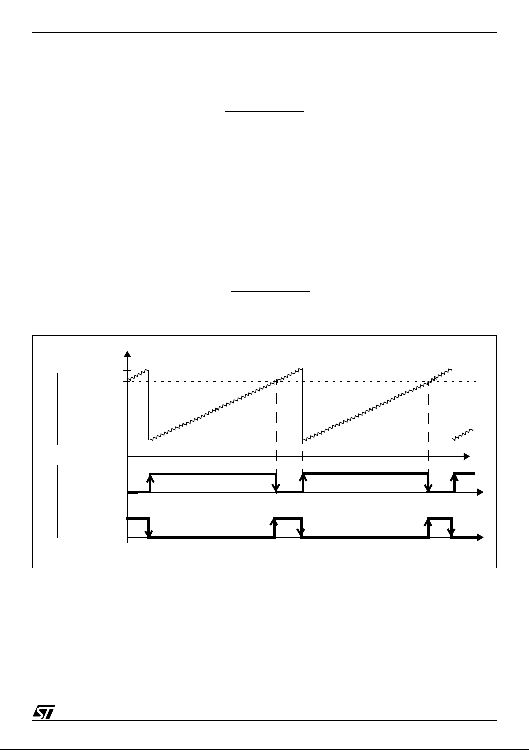
Figure 1. PWM Auto-reload Timer Function
DUTY CYCLE
REGISTER
(PWMDCRx)
AUTO-RELOAD
COUNTERPWMx O UTPUT
REGISTER
(ARTA RR)
WITH OEx=1
AND OPx=0
WITH OEx= 0
AND OPx=1
255
00
On overflow, the OVF flag of the ARTCSR register is set and an overflow interrupt request is
generated if the o verfl ow inter rupt enab le bit, O IE, i n th e ARTC S R regi ster, is s et. The OVF
flag must be reset by the user software. This interrupt is used as a time base in the application.
3/14

GENERATING A HIGH RESOLUTION SINEWAVE USING ST7 PWMART
1.2 SINEWAVE GENERATION
At the start of the program:
– the PWMDCR0 register is initialized to obtain a 50% duty cycle
– the number of samples in a sinewave cycle is defined
– the counter reload value (ARTA RR) is initia lized
In the software provided with this application note, predefined initiali zation v alues for eac h fr equency can be selected in the define.h file.
More than 18 samples in a sinewave cycle should be selected to generate a sinewave with
Total Harmonic Distortion of less than 5%. So, depending on the number of samples in a sinewave cycle, the duty cycle register (PWMD CR0) is modified, taking care that no 0% and
100% PWM is generated for any of the sinewave samples (because the PWM duty cycle must
be between ~99% to ~1% to generate an undistorted sinewave). The PWM duty cyc le is
changed after a certain number (“COUNTER”) of overflow cycles. So, the sinewave frequency
depends on three parameters,
– the PWM frequency (f
PWM
)
– the number of samples in a sinewave cycle
– the number of overflow cycles after which the PWM duty cycle changes (“COUNTER”)
So, the sinewave frequency can be given by:
1
f
=
SINE
* number of samples * COUN TER
t
PWM
See also Figure 2.
This PWM signal must be filter ed with an external RC network selected for the fi ltering level r e-
quired to generate a sinusoid. The cut off frequency of low pass RC filter is given as:
1
fH =
2 * pi * R * C
So, the value of R and C m ust be chosen in s uch a way tha t the output sinewave frequency
should be less than this high cut off frequency (f
).
H
The instantaneous value of sinewave depends on the duty cycle of PWM. So:
4/14
V
SINE max,min
V
SINE average
= Max, Min PWM duty cycle * V
= Average PWM duty cycle * V
DD
DD
GENERATING A HIGH RESOLUTION SINEWAVE USING ST7 PWMART
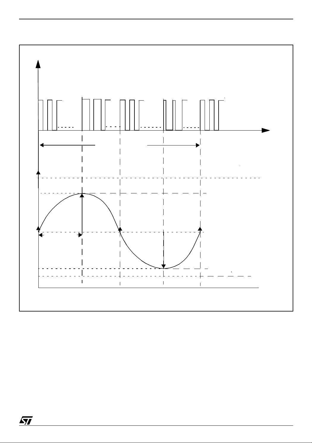
Figure 2. Output at PWM0 pin and gen e ral calculation for finding sinewave freque ncy
Number Of Samples = 4
Vdd
Output at PWM0 pin
maximum
duty cycle
= ~50%
duty cycle
= ~87%
average
duty cycle
= ~50%
minimum
duty cycle
= ~13%
= f
f
PWM
COUNTER
= 20 KHz (if f
COUNTER=10
= 1/(50us*4*10) = 500 Hz
f
SINE
duty cycle
= ~50%
/(256-ARTARR)
COUNTER
= 4MHz)
10 PWM cycles each
Output of RC circuit
255
10(=COUNTER) * t
PWMDCR0 register value
00
time
one sinewave cycle
PWMDCR0 = Average Value+75
PWMDCR0 = Average Value =
155 (PWM duty cycle = ~50%)
PWM
PWMDCR0 = Average Value-75
ARTARR=56
time
5/14

GENERATING A HIGH RESOLUTION SINEWAVE USING ST7 PWMART
2 IMPROVING SINEWAVE RESOLUTION
Sinewave resolution depends on three factors:
– t
PWM
– the number of samples in a sinewave cycle
– “COUNTER” value
By changing any of these parameters you can get a different resolution.
If f
COUNTER
is fixed, you can only change t
change you can do to ARTARR is 1. So, the minimum chan ge in t
by varying the ARTARR value. The minimum
PWM
is t
PWM
COUNTER
. For ex-
ample:
If f
COUNTER
is 4 MHz and ARTARR value is 56, then t
in a sinewave cycle is 40 and COUNTER is 10, f
If you change the ARTARR value to 57, t
will change to 49.75us. So, f
PWM
SINE
is 50us. If the number of samples
PWM
will be 50 Hz.
will be ~50.25
SINE
Hz (assuming the num ber of sampl es and COUNT ER value ar e fixed). So, the resolution is
~0.25 Hz.
Now to improve resolution, change ARTARR = 36, COU NTER = 7 and number of samples in
a sinewa ve cycle = 52.
Assuming f
COUNTER
is still 4MHz, t
will be 55us. In this case f
PWM
will be 49.95 Hz, which
SINE
gives improved resolution (~0.05Hz).
6/14

GENERATING A HIGH RESOLUTION SINEWAVE USING ST7 PWMART
3 SOFTWARE CONFIGURATION
The software is developed in “C” language and gives you the option of using the ST7 software
library or not. A header file “define.h” is supplied. This header file defines the s in structure. The
sin structure has the three user defined datatypes for stori ng sinewave patterns depending on
the number of samples in a sin ewave cycle , the “index” which is used for counting the current
sinewave sample and another datatype which is used to indicate whether the c urrent sample
is related to the upper half or lower half of the sinewave. Depending on the number of samples
in a sinewave cycle, sample values are initialized for the sinewave envelope
(X(n)=Asin((2*pi*n)/N)). where A is the sinewave amplitude, pi is 3.1416, n is the n
the sinewave, N is the number of samples in a sinewave cycle. N should be more than 18 in
order to generate a sinewave with Total Harmonic Distortion of less than 5%. The value of A
should be such that no 0% or 100% duty cycle is generated for any of the sinewave samples.
There are other define types for the sinewave frequency from 45 to 65Hz with a resolution of
less than 0.1Hz. These define types contain five parameters:
– “no_of_samples_half” for definin g the number of sa mples in half a sinewave cycle
th
sample of
– “COUNTER” value which defines the number of overflow cycles after which the PWM duty
cycle changes
– Initialization value of ARTARR for f
PWM
,
– Initialization value of PWMDCR0 a 50% duty cycle
– “AVERAGE _AM P” to define the average sinewave amplitude.
A sinewave with a resolution of less than 0.1Hz is obtained by varying the
“no_of_s amples_ half”, the “COUNTER” valu e and AR TARR . The averag e sinew ave am plitude is also software configurable by the “AVERAGE_AM P ” parameter.
It should be noted that the value of A and the value of the “AVERAGE_AMP” is chosen in such
a way that no 0% or 100% duty cycle is generated for any of the sinewave samples.
3.1 SIN STRUCTURE IN ITIALIZATION
The sin structure has the three user defined datatypes for storing the sinewave pattern according to the number of samples in a sinewave cycle, the “index” which is used for counting
the current sinewa ve sample an d another dataty pe which is used for indicating whet her the
current sample is related to the upper half or lower half of the sinewave.
7/14

GENERATING A HIGH RESOLUTION SINEWAVE USING ST7 PWMART
Figure 3. Loading of sample values and initialization of sin structure
LoadValueIntoSinStructur
Load sample values (already defined)
into value[no_of_samples_half] of sin
structure (the no of samples in half sin
wave is already defined)
Initialize Index=0
Initialize sinewave for up-
per half
return
3.2 AUTO-RELOAD TIMER INITIALIZATION
The counter is init ialized by:
– Writing to the ARTARR register to set the PWM frequency.
– Setting the FCRL (Force Counter Re-Load), the TCE (Timer Counter Enable) and OIE (Over-
flow Interrupt Enable) bits in the ARTCSR register.
In this case, the f
is CP U cl oc k ( f
INPUT
CPU
) and f
COUNTER
= f
(= 4MHz in this particular
INPUT
application).
– Enable PWM0 and configure the polarity in the PWMCR register.
– Initialize the PWMDCR0 register to define the PWM duty cycle.
8/14

GENERATING A HIGH RESOLUTION SINEWAVE USING ST7 PWMART
Figure 4. PWMAR T timer initialization
Set the frequency of PWMART
by initia liz in g the ARTA R R
Start the PWM timer counter, force
counter reload is ON & overflow interrupt
Enable PWM0 and con-
AR_TIMER_Init
is enabled
figure the polarity
Initialize the duty cycl e
of sinewave to 50%
return
3.3 PWMART INTERRUPT SERVICE ROUTINE
This is the interrupt service routine for the PWMART interrupt. Every time an overflow occurs,
an interrupt is generated (because overflow interrupt is enabled). The PWMART duty cycle is
changed af ter ev ery “CO UNTER” number of overflow cycles. The duty cycle can vary from
~99% to ~1% depending on the sinewave sample values.
9/14

GENERATING A HIGH RESOLUTION SINEWAVE USING ST7 PWMART
Figure 5. PWMART interrupt service routine
ART_Interrupt
Clears the overflow interrupt flag
no
Load the duty cycle register for up-
per half cycle of sinewave. This is
achieved by adding the current sam-
ple value into AVERAGE_AMP.
Is counter >=
COUNTER?
Load the duty cycle register for lower
half cycle of sinewave. T his is ach ieved
by subtracting the current sample value
yes
counter = 0
yes
Upper half cycle
of sinewave?
no
from AVERAGE_AMP.
10/14
yes
Index = 0 & change the po-
larity of sinewave cycle
Index = Index+1
Is Index=
no_of_samples_half?
counter = counter+1
return
no

GENERATING A HIGH RESOLUTION SINEWAVE USING ST7 PWMART
3.4 MAIN ROUTINE
The main routine calls LoadValueIntoSinStructur and AR_TIMER_Init. After this, the initialization interrupts are enabled (RIM is executed) so that the microcontroller can go into the interrupt routine and an infinite while loop is called.
Figure 6. Main routine
main
LoadValueIntoSinStructur
AR_TIMER_Init
EnableInterrupts
+
While(1)
11/14

GENERATING A HIGH RESOLUTION SINEWAVE USING ST7 PWMART
4 HARDWA RE CONFIG URATION
This application runs on an ST72F321 microcontroller. The PWM0 channel is used to generate the P WM sign al w hich i s the n f iltered by low pass filter (a s impl e RC c ircuit in this example) to generate a sinusoid. The R
C
decides the filtering level.
ext
used is 1.8K and C
ext
is 0.47uf. The values of R
ext
ext
and
The selected crystal for this example has a frequency of 8 MHz which gives f
cause the PLL is disabled and slow mode is not s elected. It gives th e f
COUNTER
the reset value of Counter Clock Control bits in ARTCSR register.
Figure 7. Generation of sinewave: Application circuitry
V
DD
VPP/ICCSEL
ST7
C = 0.1 uf
V
DD_0, VDD_1, VDD_2
V
SS_0, VSS_1, VSS_2
OSC1 OSC2
PWM0/PB3
R
C
ext
/\/\/\/\/\/\
=1.8K
ext
=0.47 uf
= 4 MHz be-
CPU
= 4 MHz for
12/14
27 pf
8 MHz
27 pf

GENERATING A HIGH RESOLUTION SINEWAVE USING ST7 PWMART
5 SOFTWARE
All th e source fi les in “C” language with the option of using the ST7 software library or not (ST7
software library version 1.1) are given in the zip file with this application note.
The source files are for guidance only. STMicroelectronics shall not be held liable for any direct, indirect or consequential damages with respect to any claims arising from use of this s oftware.
13/14

GENERATING A HIGH RESOLUTION SINEWAVE USING ST7 PWMART
THE PRESENT NOTE WHICH IS FOR GUIDANCE ONLY AIMS AT PROVIDING CUSTOMERS WITH INFORMATION
REGARDING THE IR PRO DUCT S IN OR DER FO R THEM TO SAV E TIME . AS A RES ULT, STMIC ROEL ECTR ONI CS
SHALL NOT BE HELD LIABLE FOR ANY DIRECT, INDIRECT OR CONSEQUENTIAL DAMAGES WITH RESPECT TO
ANY CLAIMS ARISING FROM THE CONTENT OF SUCH A NOTE AND/OR THE USE MADE BY CUSTOMERS OF
THE INFORMATION CONTAINED HEREIN IN CONNECTION WITH THEIR PRODUCTS.”
Information furnished is believed to be accurate and reliable. However, STMicroelectronics assumes no responsibility for the consequences
of use of such information nor for any infringement of patents or other rights of third parties which may result from its use. No license is granted
by implic ation or otherwise under any patent or p at ent rights of STMicroelectronics. Spec i fications mentioned i n this publication are subject
to change without notice. This publication supersedes and replaces all information previously supplied. STMicroelectronics products are not
authorized for use as cri tical comp onents in life support dev i ces or systems wi thout express written approval of STMicroel ectronics.
The ST logo is a registered trademark of STMic roelectronics.
All other nam es are the property of th ei r respectiv e owners
© 2004 STMi croelectro ni cs - All rights reserved
STMicroelectron i cs GROUP OF COMPANIES
Australia – Belgium - B razil - Canada - China – Czech Republi c - Finland - France - Germ any - Hong Kon g - India - Israel - Italy - Japan -
Malaysia - Malta - Morocco - Singapore - Spain - Sweden - Switzerland - United Kingdom - United States
www.st.com
14/14
 Loading...