

Page 1

AN1633
APPLICATION NOTE
DEVICE FIRMWARE UPGRADE (DFU) IMPLEMENTATION IN
NON-USB APPLICATIONS
by Microco nt rol l e r Divi s i on Ap pl ications
1 INTRODUCTION
This application note describes how to implement the Device Firmware Upgrade (DFU) capability using a ST7 USB microcontroller like the ST72F62 or ST72F63B in a general purpose or
‘non-USB’ application. The term ’non-USB’ is used here to contrast with ‘USB application’
which has a different DFU implementation (refer to AN1577). In the implementation described
here, the USB i nterfac e is not used in the applicati on. The appl ication board is self p owere d
and the on-chip USB interfac e is onl y used occasional ly, as a main tenance uti lity port to upgrade the MCU firmware.
The USB cell is only activated when the USB cable is plugged-in. At this time the application
is stopped and th e micro contro ller is seen as a USB de vice and ente rs the DF U proces s to
erase and program the new firmware in Sector 1 and/or Sector 2. When the user removes the
USB cable, the USB cell is switched-off and the main application is executed !
To illustrate this application note, a firmware example has been developed using a ST72F62
or a ST72F63B USB Low-Speed device. This firmware is based on the ST7 USB Low-Speed
DFU Demo firmware.
It is not necessary to know the USB cell to understand this application note. For more information about the USB DFU class, please refer to the Application Note AN1577.
AN1633/0303 1/9
1
Page 2
2 DFU MECHANISM
2.1 OVERVIEW
As mentioned in the introduction, the m icrocontroller’s USB cell is onl y used du ring the DFU
upgrade process. This upgrade process takes place only when the US B ca ble is plugged-in.
When the USB cable is removed the non-USB application is executed and the USB cell is
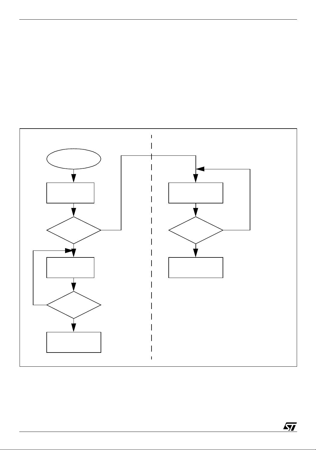
switched off. The following figure explains this mechanism in detail.
Figure 1. DFU Flowchart in a non -USB application
Yes
SECTOR 0
MCU Reset
Main (DFU)
USB cable ?
Yes
DFU Process
USB cable ?
(jump table)
No
Flash
erasing &
programming
SECTORS 1 & 2
Main (Application)
USB cable ?
Yes
WDG Reset
No
No
WDG Reset
As you can see, two s eparat e firm ware appl ications r eside in diffe re nt flash sector s and are
selected by plugging a cable in the USB connector.
2/9
2
Page 3
The first firmware application contains the USB Library, the DFU layer and the HDFlash driver.
This firmware application must be placed in Sector 0. It is executed only when the USB cable
is plugged-in. This firmware cannot be modified during the DFU process. When the Flash upgrade is finished, the firmware in Sector 0 continues execution until the USB cable is removed.
The second firm ware ap plica tion is the m ain appl ication. It m ust be pla ced in Se ctors 1 or 2
because it is modified during the DFU process. This firmware is executed only when the USB
cable is not plugged into the board.
The DFU layer also allows you to upgrade only one sector. You can use this feature, for example, to store common data or code for any firmware loaded in Sector 2.
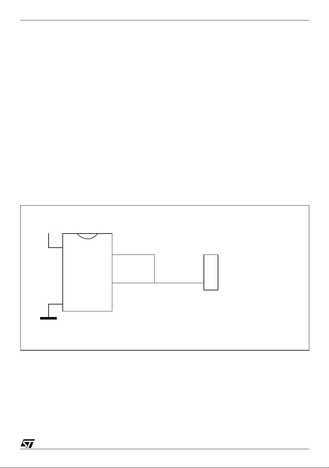
2.2 USB CABLE DETECTION
The detection of the USB cable is made through an I/O port configured in Input mode. This
I/O is connected to the Vbus li ne on the USB connector. Detection can be done with i nterrupts
or by polling. In our example, the poll ing method i s us ed. This detec tion must be performed by
both applications (main application and DFU).
Figure 2. Connecting an I/O Port to the Vbus line
+5V
Vdd
Vss
I/O
USB connector
VbusUSB Vcc
3/9
Page 4

2.3 TRANSITION BETWEEN USB AND APPLICATION
The transition between the a pplication firmware and the DF U firmw are is made only through
an MCU reset. A s oftware rese t is perform ed using the Wa tchdog con trol registe r when the
USB cable is detected.
The transition between the DFU firmware and the application firmware is made through a
“Jump Tab l e”. In fa c t, t he DFU firm w a re on ly nee ds to kn ow t he a dd ress of th e ap pli cat ion
main routine. This address is saved in the last bytes of Sector 1.
2.4 RAM
As the execution of the firmware in Sector 0 and Sectors 1 & 2 always starts after a MCU
Reset, w e h av e no R AM overl app ing prob lem . F urth ermo r e, as it is a no n-US B ap plicat ion,
there none of the USB Library functions are called by the main application. So, there is also no
problem of parameter passing. This simplifies the RAM management a lot.
4/9
Page 5

3 FIRMWARE
A specific firmware example has been developed to illustrate this application note: ST7 USB
LS DFU Demo for non-USB applications.
This firmware has been created starting from the ST7 USB LS DFU Demo firmware, itself
based on the ST7 USB LS Library and ST7 USB LS EvalKit.
The main changes concern the size optimization of the USB Library and the DFU layer in
order to use a little space as possible in Sector 0. Currently the space required by the USB Library and the DFU layer is around 2 Kbytes. This optimization leaves 2 Kbytes of code for running the application during the DFU process or using it for code that does not need to be upgraded.
This firmware is compatible with Cosmic and Metrowerks compilers.
3.1 MAIN APPLICATION FUNCTION EXAMPLE
void main(void) {
Init_Appli();
while (1) {
// MANDATORY: USED TO GO INTO DFU MODE WHEN THE USB CABLE IS PLUGGED
if (ValBit(PBDR, 5)) { // Check if Vbus is present ?
Stop_Appli();
WDGCR = 0x80; // MCU Reset
}
else {
Application();
}
} // End of while
} // End of main
3.2 DEVICE INFORMATION EXAMPLE
As the application is non-USB, we don’t have the U SB descriptors. The descriptors normally
contain strings like: Manufacturer name, Product name, firmware ver sion, ...
Because it is very useful to know which product is connected to the USB, a kind of string descriptor has been created in this project.
The principle is very simple: a fixed table contains the address and the size of thes e string descriptors (for example the Product name and its version). The host retreives this information
using a DFU_UPLOAD request. It is then possible to display these strings on a Graphical User
Interface.
5/9
Page 6

In the de mo fir mwa re thi s tab le ha s been pla ced at t he en d of Sec tor 1 , it co ntain s the f ollowing information: Jump to main function, product string address, product string length, version string address, version string length, flash size.
This is only an example and you can decide to create more strings or none.
4 GRAPHICAL USER INTERFACE
A specific GUI has been developed for this project. This GUI is only given as example.
Main features:
- Developed with Borland Delphi5
- Uses the ST7DFU.DLL developed by STMicroelectronics to access the DFU low level layer.
- Retreives the string information described above.
- Reads and writes files in S19 format
- Selects Sector 1 and 2 independently.
6/9
Page 7

5 RELATED DOCUMENTS & FIRMWARE
Table 1. External Docu ments
Name
Universal Serial Bus Specification, V1.1
Universal Serial Bus Device Class Specifi cation for Device Firmware
Upgrade, V1.0
Table 2. STM Docu ments
Name
ST7 Family Flash Programming Reference Ma nual
AN1575 “On-Board Programming Methods for XFlash and HDFlash
ST7 MCUs”
AN1576 “In-Application Programming Drivers for XFlash and HDFlash ST7 MCUs”
AN1577 “Device Firmware Upgrade implementation in ST7 USB devices”
Table 3. Firmware
ST7 USB LS DFU Demo for non-UB application
Name
7/9
Page 8

6 TERMS AND ABBREVIATIONS
Table 4. Terms and Abbreviations
Term Definition
DFU
Firmware
GUI
Upgrade
Download
Upload
Device Firmware Upgrade.
Executable software stored in a write-able, nonvolatile memory on a
USB device.
Graphical User Interface
(1) To overwrite the firmware of a device, (2) the act of overwriting the
firmware of a device, (3) new firmware intended to replace a device’s
existing firmware.
To transmit information from host to device.
To transmit information from device to host.
8/9
Page 9

“THE PRESENT NOTE WHICH IS FOR GUIDANCE ONLY AIMS AT PROVIDING CUSTOMERS WITH
INFORMATION REGARDING THEIR PRODUCTS IN ORDER FOR THEM TO SAVE TIME. AS A RESULT, STMICROELECTRONICS SHALL NOT BE HELD LIABLE FOR ANY DIRECT, INDIRECT OR
CONSEQUENT IAL DAMAGES WI TH RESPECT TO ANY CLAIMS ARIS ING FROM THE CONTENT OF
SUCH A NOTE AND/OR THE USE MADE BY CUSTOMERS OF THE INFORMATION CONTAINED
HEREIN IN CONNECTION WITH THEIR PRODUCTS.”
Information furnished is believed to be accurate and reliable. However, STMicroelectronics assumes no responsibility for the consequences
of use of such information nor for any infringement of patents or other rights of third parties which may result from its use. No license is granted
by implic ation or otherwise under any patent or patent r i ghts of STM i croelectronics. Specificat i ons menti oned in thi s publication are subject
to change without notice. This publication supersedes and replaces all information previously supplied. STMicroelectronics products are not
authorized for use as cri tical comp onents in lif e support dev i ces or systems wi thout the express writ t en approval of STM i croelectronics.
The ST logo is a registered trademark of STMicroelectronics
2003 STMicroelectronics - All Rights Reserved.
STMicroelectronics Grou p of Compan i es
http://www.s t. com
Purchase of I
2
C Components by STMicroelectronics conveys a license under the Philips I2C Patent. Rights to use the se compone nt s i n an
2
I
C system i s granted pro vi ded that the system con forms to the I2C Standard Specification as defined by Philips.
Australi a - Brazil - Canada - China - Fi nl and - Franc e - Germany - Hong Kong - Ind ia - Israel - Italy - Japan
Malaysi a - M al ta - Morocco - Singapore - Spain - Sw eden - Switz erland - United Kingdom - U.S.A.
9/9
 Loading...