

Page 1
AN1601
APPLICATION NOTE
SOFTWARE IMPLEMENTATION FOR ST7DALI-EVAL
INTRODUCTION
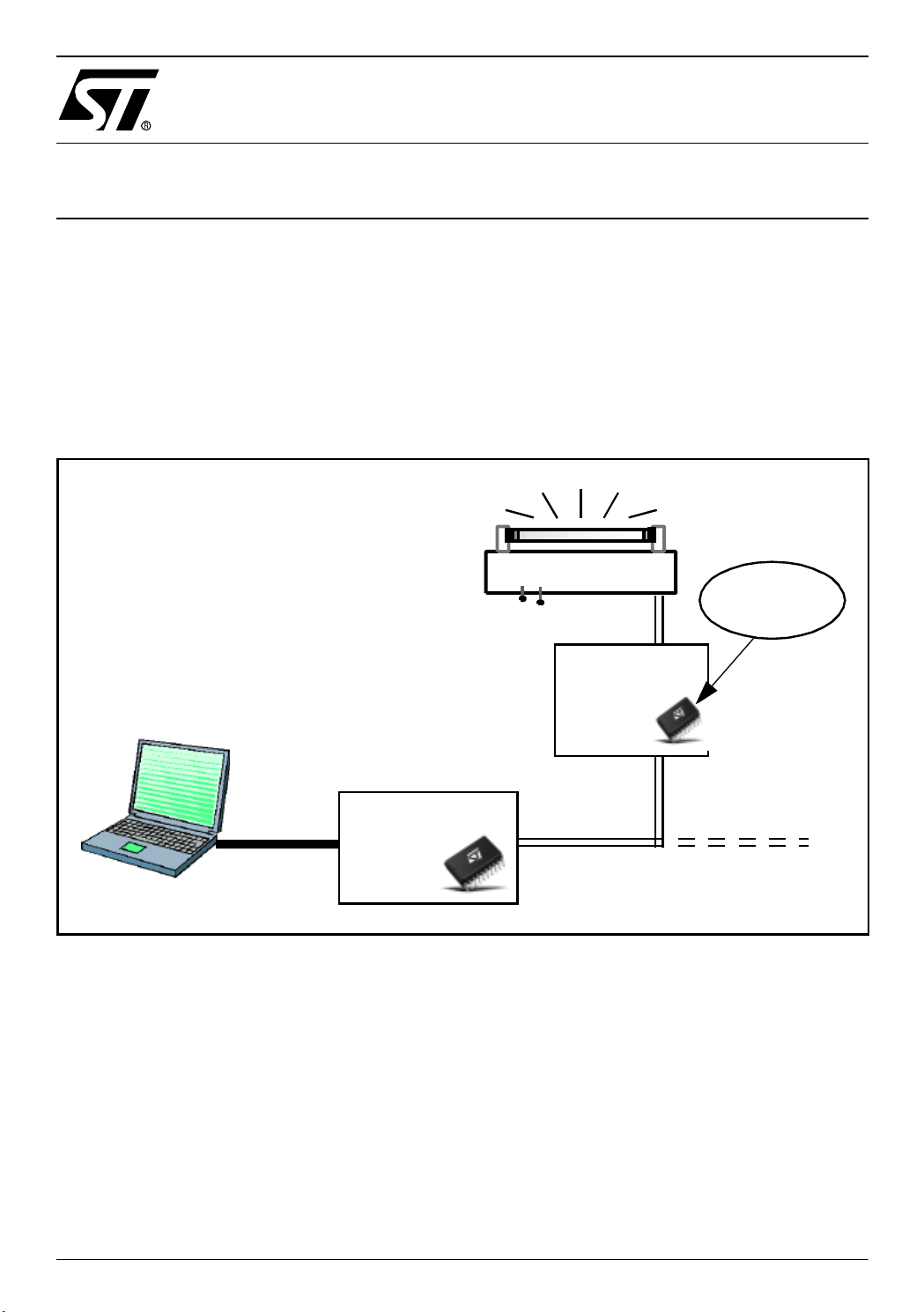
This application note des cribes a software ex ample for driv ing a DALI slave board using an
ST7DALI (ST7LITE2 family) microcontroller. It is supplied with the kit ST7DALI-EVAL and can
be ordered with the code ST7DALI-EVAL.
The software is written in C language and is compatible with both Metrowerks and Cosmic
compilers.
Lamp-Ballast
DALI sl ave
1-10 V
software
DALI
master
board
DALI
slave
board
DALI network
Rev. 1.1
AN1601/0404 1/23
1
Page 2
SOFTWARE IMPLEMENTATION FO R ST7DALI-EVAL
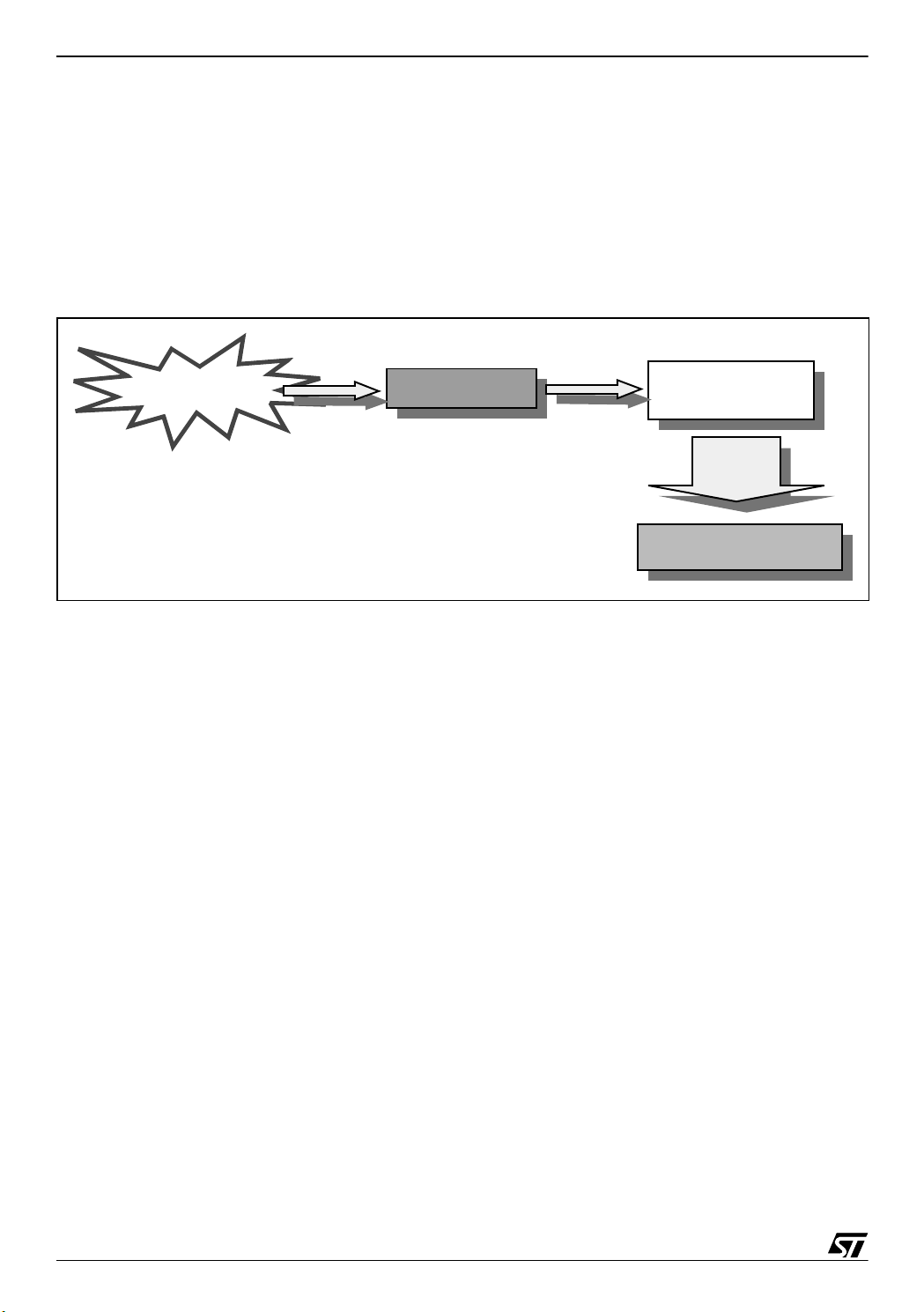
1 PROCESS OV ERVIEW
First of all, the DALI slave software initializes the slave system; afterwards, when the DALI
master board sends a forward frame (basically 1 address byte and 1 data byte), and the DALI
slave board receives the forward frame, a DALI interrupt (IT) is generated. This interrupt sets
a flag, when this flag is set, the program che cks whether the c ommand is addr essed to this
ballast or not. If the c ommand is a ddress ed to thi s ballast the comman d hand ling process is
started and the DALI slave board reacts to the received command.
New frame arrival
Dali IT
Main.c
Process
command
DALI_CMD
2/23
2
Page 3
SOFTWARE IMPLEMENTATION FOR ST7DALI-EVAL
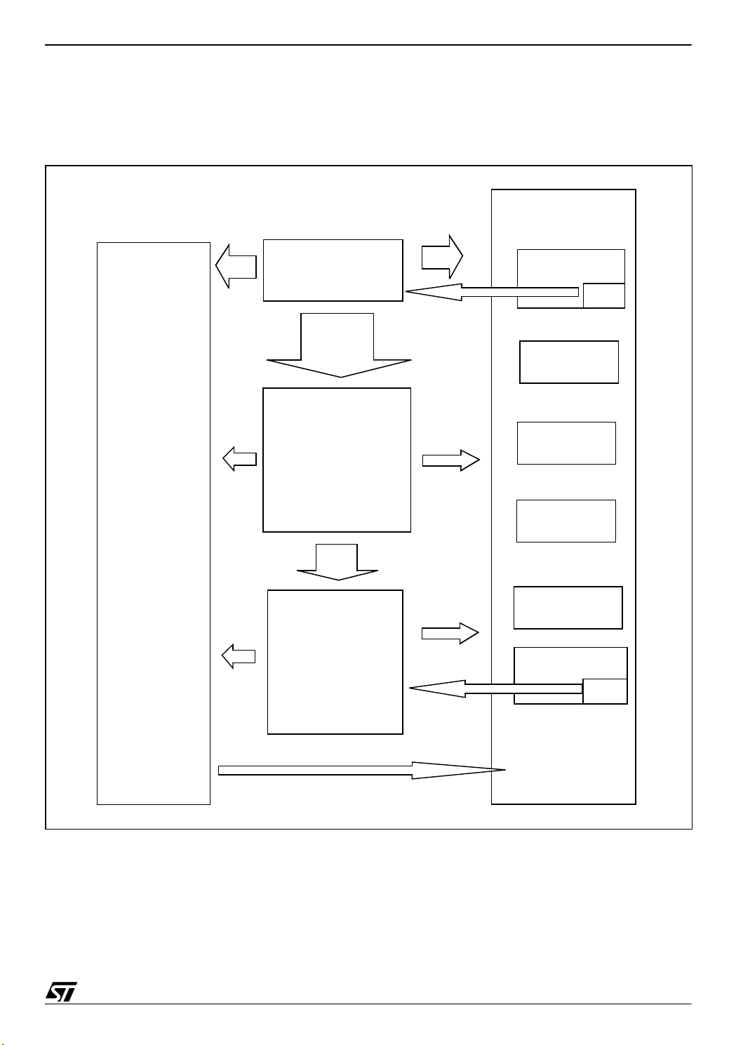
2 GENERAL STRUCTURE OF THE DALI S LA VE SOFTW ARE
The following diagram shows the different software modules and their relationships.
Figure 1. General Block Diagram
PERIPHERAL
MODULES
DALI_REG
(DALI registers)
Init
main. c
Process
Command
DALI_CMD
(DALI commands)
DALI_PUB
Inits
Dali
IT
clock_reset_
supply
ports
main_clock_
contr
pwm_ar_timer
_12bit
lite_timer_8bit
IT
EEPROM
Note: The names of DALI_CMD module functions are prefixed by DALIC_. DALI_REG
module functions are prefixed by DALIR_, and DALI_PUB module functions are prefixed by
DALIP_.
3/23
Page 4

SOFTWARE IMPLEMENTATION FO R ST7DALI-EVAL
3 MODULE DE SCRIPTIONS
3.1 MAIN.C MODUL E
For DALI communication, the microcontroller has to monitor the low voltage state on the DALI
bus (it is not allowed to be more than 500ms), and so it needs a process to differentiate a
frame reception from a bus down.
This module calls all the ini tiali zation routines in the other modules, then i t calls the r outines to
switch on the red and green LEDs on the board, and finally it enters an infinite loop.
This loop could be divided in two par ts, the managem ent of the low vo ltage condition of the
DALI BUS and fade rate plus the management of the new D ALI frame reception.
The management of the low voltage condition and fade rate i s obtained using a st ate machine,
synchronized with a period of 1 ms, in fact the lite_timer_IT_state variable is set to one every
1 ms.
To better understand how it works, please refer to Figure 12 in appendix A.
To manage the DALI frame reception, it checks the "dali_receive_status" flag in order to see
if a new forward frame has been received by the microcontroller (MCU). If so, it calls the
"DALIC_isTalkingToMe" function to check whether the comma nd is addressed to this ballast
or not. If it is, it switches on the green LED and starts the command handling process; otherwise it switch es on the red LED. Fin ally it rese ts the "dali_ receive _statu s" flag to rest art the
cycle.
3.2 DALI_CMD MODULE
The main purpose of this module is to handle the DALI commands.
DALI_CMD contains several functions, most of them handle a particular DALI command, but
three of them are called from outside the module (from main.c):
1) The “DALIC_Init”, function initializes the ballast at its “POWER_ON_LEVEL”.
2) The “DALIC_isTalkingToMe” function, checks whether the command is addressed to this
ballast or not.
3) The “DALIC_ProcessCommand” function is the first step in the process of executing a
command. It checks if a repetition fault has occurred (according to the specification, another command between an expected repetition is ignored and leads to the cancellation of
the repetition sequence) and it checks whether the command is a special one or a normal
one.
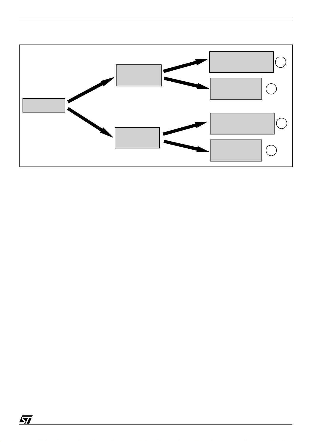
The sequence continues as shown in Figure 2:
4/23
Page 5
SOFTWARE IMPLEMENTATION FOR ST7DALI-EVAL
Figure 2. DALI_CMD Module Sequence
Reserved special
command
a
Special
command
Other special
command
b
Command
Direct arc power
c
control command
Normal
command
Other normal
command
d
Notes:
a) “DALIP_Reserved_Special_Function” is called. This function is empty, it is reserved for fu-
ture needs.
b) The function for handling a special command is called through the “special_jt” table.
c) The “DALIC_Direct_Arc” function handles this kind of command.
d) The function for handling a normal command, is called through the “normal_jt” table (that
points to the function).
Note: In the case of COSMIC compilation, this is divided into thr ee tabl es to avoid “long array”
problems (this COSMIC problem has since been solved).
3.3 DALI_REG MODULE
In accordance with the DALI spec ification, some data variables giving information on the ballast and its status have to be stored in memory; we refer to these variables as DALI registers.
The DALI_REG module handles the reading and writing of the DALI registers. It allows access
to any of the DALI reg isters in the s ame wa y, whe rever t hey are physic ally sit uated ( ROM,
EEPROM, RAM ).
Normally you don’t need to use the functions of this module directly (you can access most of
these registers using the functions defined for this pur pose in the DA LI_PUB module). H owever, in case you need direct access to the registers, you can find the description of these
functions and how to use them in Appendix B.
5/23
Page 6

SOFTWARE IMPLEMENTATION FO R ST7DALI-EVAL
3.4 PERIPHERAL MODULES
The purpose of these modules is to handle the different peri pherals and hardware blocks of
the MCU, each one is in charge of a specific block.
All these modules have the same file structure. Each module has three files:
– xxx_hr.h where all or part of the registers and the register bits are defined.
– xxx.h that contains the d eclaration of the public functions and constants.
– xxx.c that contains the function routines.
(xxx represents the name of the module)
3.4.1 “clock_reset_supply” module
This module handles the “RC Oscillator Control” Register (RCCR) and the “System Integrity
Control/Status” Register (SICSR). In the current version, it just configures the RCCR to calibrate the RC oscillator frequency. Two factory calibration values are store d in the first two
EEPROM addresses, however you can calibrate the RC with a different value. Please refer to
the ST7FDALI datasheet SUPPLY, RESET AND CLOCK MANAGEMENT section for more
details.
3.4.2 “dali” module
This module handles the DALI peripheral.
It initializes the peripheral (DALI_Init function), and contains the DALI interrupt routine that
handles the arrival of a forward frame. It also contains the (Send_DALI_Frame) function that
allows sending backward frames to the master boar d. Please refer to t he ST7FDALI da tasheet, section DALI CO MMUNICATION MODULE for more details.
3.4.3 “eeprom” module
This module handles the EEPROM of the MCU.
It initializes the EEPROM, so it saves the DALI regi sters (their reset values) in the EE PR OM
the first time that the program is started. It also contains the functions in charge of the physical
reading and writing of the EEPROM. When you use the EEPROM, you don’t need to use
these functions directly, since a group of functions for handling the EEPROM is defined in the
DALI_PUB module.
3.4.4 “lite_timer_8bit” mod ule
This module handles the Lite Timer peripheral (Two 8-bit upcounters for timing purposes). In
the current version, it just uses upcounter 1.
It initializes the Lite Timer so that the interrupt routine is run every 1 ms, this routine carries out
the various countdowns required by the program.
6/23
Page 7

SOFTWARE IMPLEMENTATION FOR ST7DALI-EVAL
3.4.5 “main_clock_contr” mo dule
This module contains the Main Clock Control initialization routine that handles the Main Clock
Control/Status Register (MCCSR). In the current version, it enables the MCO output clock; i.e.
the CPU clock signal can be seen on this pin.
3.4.6 “ports” module
This module handles the MCU I/O ports. In the current version of the software, this application
just uses the PA1 and PA2 ports; they are used as outputs for switching the LEDs on and off,
to indicate whether a forward frame has been addressed to this ballast or not.
3.4.7 “pwm_ar_timer_12bit” module
This module controls the 12-bit autoreload timer.
In this application the 12-bit autorel oad timer is used for gene rating a PW M signa l to c ontrol
the power level of the lamp (the PWM duty cycle determines the DC output level of the slave
board).
So, the purpose of this module is to initialize the timer and set up the PWM duty cycle according to the command received.
3.5 DALI_PUB MODULE
This module has to be m odified (if n eeded ) by the us er. The fol lowing sections desc ribe the
main parts of the module.
3.5.1 ROM registers
According the DALI sp ecification, t he DA LI “ve rsion numbe r” a nd “phy sical min. level” re gis ters have to be stored in ROM, these two values are defined in this module by the “ROMRegs”
table as follows: ROMRegs[]={0,25}, where the first value is the “version number” and the
second is the “physical min. level”, you can modify thes e values according to the bal last used.
3.5.2 Fading functions
“DALIP_LaunchTimer”: starts a countdown in the Lite Timer interrupt routine (“lite_timer_8bit”
module), so that the “DALIP_TimerCallback” function is called every 1ms. The parameter
passed represent s the number of times th at the function “DA LIP_T imerCa llback” will be
called, but i f you pass 0xF F th e fu nctio n wil l be called eve ry 1ms no n s top un til the functi on
“DALIP_DoneTimer” is c alled.
“DALIP_DoneTimer”: is used to stop the tim e r started by “DALIP_LaunchTimer”. It should be
called as soon as the process is finished to let the MCU enter in SLOW-WAIT-MODE (in order
to save power) if it has nothing more to do.
7/23
Page 8

SOFTWARE IMPLEMENTATION FO R ST7DALI-EVAL
“DALIP_Ti m erC al lback”: hand les th e fad ing effe ct; basica lly , it in crea ses or decre ase s (one
step) the arc power level every “DALIP_iChangeEvery” ms (according to the DALI command
processed and the fade time/rate selected), until the required power level is reached.
3.5.3 Arc power control functions
The following functions are the last step in the process of all “arc power control” comma nds:
DALIP_Direct_Arc, DALIP_Off, DALIP_Up, DALIP_Down, DALIP_Step_Up,
DALIP_Step_Down, DALIP_Step_Down_And_Off, DALIP_On_And_Step_Up. They set the
new power level and update the “actu al dim le vel” register. DALIP_Off, DALIP_Up and
DALIP_Direct_Arc (if necessary) calculate the “DALIP_iChangeEvery” value used by the
“DALIP_TimerCallback” function, this v alue is calculated according the c u rrent fade time/rate
value to carry out the fading process.
Note: All the above functions correspond to DALI commands described in the DALI specification.
3.5.4 DALI register access functions
The following functions al low you to wr ite and read mo st of the spec ific DALI re gisters (see
DALI spec.). I f you n eed to acce ss the registers directly, refer to the DALI_R EG modul e de scription.
The Write Functions pass just one parameter to update a particular DALI register and returns
nothing:
Table 1. List of DALI Register Write functions
Write-Functions DALI register affected
DALIP_SetArc Actual dim level
DALIP_SetBallastStatusFlag Status information (bit 0)
DALIP_SetLampFailureFlag Status information (bit 1)
DALIP_SetLampPowerOnFl ag Status information (bit 2)
DALIP_SetFadeReadyFlag Status information (bit 4)
DALIP_SetPowerFailureFlag Status information (bit 7)
Note: For Flag Registers, pass 0 to clear the Bit and !=0 to set it.
The Read Functions return the current value of a particular DALI register:
Table 2. List of DALI Register Read functions
Read-Function DALI register affected
DALIP_GetArc Actual dim level
DALIP_GetFadeTime Fade time
DALIP_GetFadeRate Fade rate
DALIP_GetMaxLevel Max level
DALIP_GetMinLevel Min level
DALIP_GetPowerOnL evel Power on level
8/23
Page 9

SOFTWARE IMPLEMENTATION FOR ST7DALI-EVAL
DALIP_ G etSysFailur e Level Syste m failure level
DALIP_GetSta tu s Status informati o n
DALIP_GetVersion Version number
DALIP_GetPhysMi n Level Physical min. level
3.5.5 EEPROM access functions
Using thes e functi ons, y ou can re ad and wri te to the c onnec ted EEP ROM . The ad dressi ng
range is from 0 to the return-value of DALIP_EEPROM_Size. Accesses outside that range will
be ignored.
Note: The returned EEPROM-Size i s the actual size minus a few by tes that are used for
saving the DALI-Registers. There is maximum size of 256 bytes for the connected EEPROM.
(Bigger ones work too, but only the lower 256 bytes can be accessed).
Caution: If a Page- Write ex ceeds the addressing range, the WHO LE Write Operation will be
ignored!
DALIP_EEPROM_Siz e
Return: Highest address that can be passed to an EEPROM -Access-Command
DALIP_Read_E2
Reads one byte from the passed address
Param1: Address to be read
Return: Data byte read from the EEPROM
DALIP_Write_E2
Writes one byte to the passed address
Param1: Address to write to
Param2: Data byte to be written
DALIP_Write_E2_Buffer
Writes a sequence of Bytes (uses the page-write-operation of the EEPROM to be faster)
Param1: First Address to write to
Param2: Number of Bytes to be w r itten
Param3: Pointer to the first byte of the array that contains the data
3.5.6 Reserved functions
Many commands in the DALI specification are reserved for future needs. When a forward
frame calls for one of these commands, one of the following functions is called. Either
“DALIP_Reserved_Function” if the reserved command is not special (commands in the range
9/23
Page 10

SOFTWARE IMPLEMENTATION FO R ST7DALI-EVAL
0-255) or “DALIP_R eserved_Special_Func ti on” if it’s a s pecial command (commands in the
range 256-287).
At present these functions are empty.
3.5.7 Other functions DALIP_Is_Physically_Selected
This function returns 1 if the device is physically selected, otherwise it returns 0.
Since the first case it is not yet implemented, at present it alwa ys returns 0.
DALIP_What_Device_Type
This function returns a number that corresponds with the type of the device used. At present
it returns 0 that means “device for fluorescent lamps” accor ding to th e D ALI spec ific a tion , so
you should specify here the type if it is a different one.
10/23
Page 11

APPENDI X A. FLOW CHARTS
Figure 3. Main.c Flowchart
POWER_ON_LEVEL va lue
no
SOFTWARE IMPLEMENTATION FOR ST7DALI-EVAL
Compiler Init
Peripherals Init
Switch onLEDs
Enable interrupts
Set light le v el @
yes
lite_timer_IT_state=1
State Machine
no
Switch on red LED
no
new Frame?
(is dali_receive_status flag set?)
yes
Switch off
Command addressed to this ballast?
(DALIC_isTalkingToMe?)
Restore Status
(reset dali_receive_status flag)
LEDs
yes
Switch on green LED
Process Command
11/23
Page 12

SOFTWARE IMPLEMENTATION FO R ST7DALI-EVAL
Figure 4. DALIC_is_talking_to_me @ d ali_cmd.c
DALIC_is_talking_to_me
clr b_is_special flag
no
return 0
special?
no
broadcast?
no
group?
no
direct?
yes
return
1
yes
yes
yes
return 1
mask group
group 0..7?
no
group 8..15?
set b_is_special flag
return 1
yes
return 1
yes
12/23
no
return 0
return 1
Page 13

SOFTWARE IMPLEMENTATION FOR ST7DALI-EVAL
Figure 5. DALIC_ProcessCommand @ dali_cmd.c
DALIC_ProcessCommand
yes
DALIC_Is_Repetiton_Fault?
no
yes
Special Command?
Return
no
DALIC_ProcessNormalCommand
Return
DALIC_ProcessSpecialCommand
Return
13/23
Page 14

SOFTWARE IMPLEMENTATION FO R ST7DALI-EVAL
Figure 6. DALIC_ProcessSpecialC ommand @ dali_cmd.c
DALIC_ProcessSpecialCommand
yes
Reserved Command?
no
DALIP_Reserved_Special_Function
Return
Execute desired special
command routine
(function jump table)
Return
14/23
Page 15

SOFTWARE IMPLEMENTATION FOR ST7DALI-EVAL
Figure 7. DALIC_ProcessNormalCommand @ dali_cmd.c
DALIC_ProcessNormalCommand
address last bit = 1?
yes
Execute desired command
routine (function jump
table)
Return
no
DALIC_Direct_Arc
Return
15/23
Page 16

SOFTWARE IMPLEMENTATION FO R ST7DALI-EVAL
Figure 8. DALIC_Is_Repetition_Fault @ dali_cmd.c
DALIC_Is_Repetiton_Fault
IsFlag(b_is_cmd_buffered)? Return 0
yes
No time out & buffer!= Dali
no
Time out?
no
No time out & buffer = Dali message?
no
message?
yes
no
yes
(b_is_cmd_inbetween)
yes
IsFlag (b_is_cmd_inbetween)?
SetFlag
Return 1
ClrFlag
(b_is_cmd_buffered)
ClrFlag
(b_is_cmd_inbetween)
Return 0
no
16/23
ClrFlag
(b_is_cmd_buffered)
ClrFlag
(b_is_cmd_inbetween)
Return 0
yes
ClrFlag
(b_is_cmd_buffered)
ClrFlag
(b_is_cmd_inbetween)
Return 1
Return 0
Page 17

SOFTWARE IMPLEMENTATION FOR ST7DALI-EVAL
Figure 9. DALIC_Direct_Arc @ da li_cmd.c
DALIC_Direct_Arc
yes
data = 255?
no
Return
data = 0?
no
Set LAMP_ARC_POWER_ON
flag
data < MIN_LEVEL
no
data > MAX_LEVEL
no
Clear LIMIT_ERROR flag
DALIP_Direct_Arc
at data level
yes
?
?
yes
yes
Clear LAMP_ARC_POWER_ON
flag
DALIP_Off
Return
Set LIMIT_ERROR
flag
DALIP_Direct_Arc
at MIN_LEVEL
Return
Set LIMIT_ERROR
flag
DALIP_Direct_Arc
at MAX_LEVEL
Return
Return
17/23
Page 18

SOFTWARE IMPLEMENTATION FO R ST7DALI-EVAL
Figure 10. DALIC_Is_Repeated @ dali_cmd.c
DALIC_Is_Repeated
no
IsFlag(b_is_cmd_buffered)?
yes
ClrFlag(b_is_cmd_buffered)
yes
Time out ?
no
buffer = Dali message?
no
Return 0
Return 0
yes
Return 1
buffer = Dali
SetFlag(b_is_cmd_buffered)
RTC_LaunchTimer(DAL
I_REPETITION_WAIT)
message
Return 0
18/23
Page 19

SOFTWARE IMPLEMENTATION FOR ST7DALI-EVAL
Figure 11. DALIP_Direct_Arc @ DALI_PU B.C
DALIP_Direct_Arc
Data level = current level?
no
Turn off timer
(DALIP_DoneTimer)
Fade time = 0?
yes
no
Presen t po wer level > da t a level?
no
Set DALIP_bIncrease
flag
Calcul
DALIP_iChangeEvery
yes
yes
DALIP_bIncrease
DALIP_iChangeEvery
Return
clear
flag
Calcul
Update
ACTUAL_DIM_LEVEL
variable (DALIP_SetArc)
Set new PWM duty cycl e
(AR_TIMER_Set_PWM)
Return
Set fad e ready flag (f ade is
running)
DALIP_LaunchTimer(0xFF)
Return
19/23
Page 20

SOFTWARE IMPLEMENTATION FO R ST7DALI-EVAL
Figure 12. State Machine diagram
Process_Status_0
If DALIBUS == LOW
Process_Status_1
If DALIBUS == HIGH
If DALIBUS == HIGH
Initialize Bus Failure Timer
Disable Interrupt PB5
If Bus Failure Timer != 0
Process_Status_2
If DALIBUS == LOW
Decrease Bus Failure Timer
If Bus Failure Timer == 0
Process_Status_3
Reset Bus Failure Timer
Enable Interrupt PB5
Set Bus Failure
20/23
Page 21

SOFTWARE IMPLEMENTATION FOR ST7DALI-EVAL
APPENDI X B. DALI_REG MODULE FUNCTIONS
The program makes use of the following functions of the DALI_REG module to read/write the
DALI registers easily:
DALIR_ReadReg
Purpose: it reads the value of one register.
Parameters: name of the register to be read
Returns: value of the register
DALIR_WriteReg
Purpose: It writes to one of the DALI-Registers
Parameters: Name of the register to be write, new value
Returns: --
DALIR_WriteStatusBit
Purpose: To reset/clear one bit of the DALIREG_STATUS_INFORMATION register.
Parameters: name of the bit, 0 to reset the bit and !=0 to set it.
Returns: --
DALIR_ReadStatusBit
Purpose: It reads the value of one bit of the DALIREG_STATUS_INFORMATION register.
Parameters: name of the bit to be read.
Returns: bit value (0 or 1).
Other DALI_REG functions:
DALIR_Init
Purpose: it initialises the RAM-registers to zero.
Parameters: -Returns: --
DALIR_ResetRegs
Purpose: It initialises the DALI registers to their “reset value” (the “reset
value” for each register is specified the DALI specification)
Parameters: -Returns: --
DALIR_LoadRegsFromE2
Purpose: It loads the DALIREG_SHORT_ADDRESS into the “short_addr” variable (function used just in the EEPROM init).
Parameters: -Returns: --
21/23
Page 22

SOFTWARE IMPLEMENTATION FO R ST7DALI-EVAL
DALIR_DeleteShort
Purpose: It writes 0xFF in the DALIREG_SHORT_ADDRESS register, which means that no
address is ascribed to this ballast (mask).
Parameters: -Returns: --
The names of the registers are defined in dali_regs.h as follows:
RAM-Registers:
DALIREG_ACTUAL_DIM_LEVEL (1 byte)
DALIREG_SEARCH_ADDRESS (3 bytes)
DALIREG_STATUS_INFORMATION (1 byte):
Bit 0: DALIREG_STATUS_BALLAST
Bit 1: DALIREG_STATUS_LAMP_FAILURE
Bit 2: DALIREG_STATUS_LAMP_ARC_POWER_ON
Bit 3: DALIREG_STATUS_LIMIT_ERROR
Bit 4: DALIREG_STATUS_FADE_READY
Bit 5: DALIREG_STATUS_RESET_STATE
Bit 6: DALIREG_STATUS_MISSING_SHORT
Bit 7: DALIREG_STATUS_POWER_FAILURE
E²PROM-Registers:
DALIREG_POWER_ON_LEVEL (1 byte)
DALIREG_SYSTEM_FAILURE_LEVEL (1 byte)
DALIREG_MIN_LEVEL (1 byte)
DALIREG_MAX_LEVEL (1 byte)
DALIREG_FADE_RATE (1 byte)
DALIREG_FADE_TIME (1 byte)
DALIREG_SHORT_ADDRESS (1 byte)
DALIREG_RANDOM_ADDRESS (3 bytes)
DALIREG_GROUP_0_7 (1 byte)
DALIREG_GROUP_8_15 (1 byte)
DALIREG_SCENE (16 bytes)
ROM-Registers:
DALIREG_VERSION_NUMBER (1 byte)
DALIREG_PHYS_MIN_LEVEL (1 byte)
22/23
Page 23

SOFTWARE IMPLEMENTATION FOR ST7DALI-EVAL
“THE PRESENT NOTE WHICH IS FOR GUIDANCE ONLY AIMS AT PROVIDING CUSTOMERS WITH INFORMATION
REGARDING THE IR PRO DUCT S IN OR DER FO R THEM TO SAV E TIME . AS A RES ULT, STMIC ROEL ECTR ONI CS
SHALL NOT BE HELD LIABLE FOR ANY DIRECT, INDIRECT OR CONSEQUENTIAL DAMAGES WITH RESPECT TO
ANY CLAIMS ARISING FROM THE CONTENT OF SUCH A NOTE AND/OR THE USE MADE BY CUSTOMERS OF
THE INFORMATION CONTAINED HEREIN IN CONNECTION WITH THEIR PRODUCTS.”
Information furnished is believed to be accurate and reliable. However, STMicroelectronics assumes no responsibility for the consequences
of use of such information nor for any infringement of patents or other rights of third parties which may result from its use. No license is granted
by implic ation or oth erwise unde r any patent or patent r i ghts of STMi croelectroni cs. Speci fications me ntioned in this publicat i on are subject
to change without notice. This publication supersedes and replaces all information previously supplied. STMicroelectronics products are not
authorized for use as critical components in life su pport device s or systems without express written approval of STMicroelectronics.
The ST logo is a register ed t rademark of ST M i croelectroni c s.
All other nam es are the pro perty of their respective ow ners
© 2004 STMi croelectroni cs - All rights reserved
STMicroelectron i cs GROUP OF COMPANIES
Australia – Belgium - B razil - Canad a - China – Czech Republic - Finl and - France - Ger many - Hong Kong - India - Israel - Italy - Japan -
Malaysia - Malta - Morocco - Singapore - Spain - Sweden - Switzerland - United Kingdom - United States
www.st.com
23/23
 Loading...