

Page 1

AN1577
APPLICATION NOTE
DEVICE FIRMWARE UPGRADE (DFU) IMPLEMENTATION IN
ST7 USB DEVICES
by Microcontroller Division Applications
1 INTRODUCTION
This application note p resents th e imple mentation of a Device Firmw are Upg rad e (DF U) capability in ST7 USB microcontrollers. It follows the DFU class specification defined by the USB
Impleme nters Forum , for reprog ramm ing an app licat ion throu gh USB . The DFU prin ciple is
particularly well suited to USB applications that require need to be reprogrammed in the field:
The same USB connector can be used both for the standard operating mode, and for the reprogramming process.
This operation is made possible by the IAP capability featured by mos t of the ST7 mi crocontrollers, which allows a FLASH MCU to be reprogrammed by any communication channel
(Please refer to AN1575 for more details).
The DFU process, like any other IAP process, is based on the execution of firmware located in
Sector 0 of the ST7 Flash memory which manage the Flas h operations (erasing and pr ogramming) of Sectors 1 and 2.
This application note covers then two main aspects:
The firmware located in Sector 0,
The Interface between the firmware in Sector 0 and the firmware in Sectors 1 & 2.
The proposed implementation is demonstrated with 2 different projects: the USB Low -Speed
devices Evaluation Kit and the ST7265 Full-Speed 5-in-1 demoboard. In this document these
projects are referred to as “LS project” and “FS project”.
A basic DFU protocol is also used in these projects. The modular approach used in the imple-
mentation based on a DFU library allows you to adapt it easily to other higher level protocols
or new types of hardware.
AN1577/0103 1/30
1
Page 2

DEVICE FIRMW ARE UPGRADE (DFU) IMPLEMENTAT ION IN ST7 USB D EVICES
1 INTRODUCTION . . . . . . . . . . . . . . . . . . . . . . . . . . . . . . . . . . . . . . . . . . . . . . . . . 1
2 DFU CLASS . . . . . . . . . . . . . . . . . . . . . . . . . . . . . . . . . . . . . . . . . . . . . . . . . . . . 4
2.1 INTRODU CTION . . . . . . . . . . . . . . . . . . . . . . . . . . . . . . . . . . . . . . . . . . . . 4
2.2 PHASES . . . . . . . . . . . . . . . . . . . . . . . . . . . . . . . . . . . . . . . . . . . . . . . . . . . 4
2.3 REQUESTS . . . . . . . . . . . . . . . . . . . . . . . . . . . . . . . . . . . . . . . . . . . . . . . . 5
2.4 ENUMERA TION PHASE . . . . . . . . . . . . . . . . . . . . . . . . . . . . . . . . . . . . . . 5
2.4.1 Run-Time Descriptor Set . . . . . . . . . . . . . . . . . . . . . . . . . . . . . . . . . . . . . . . . . 6
2.4.2 DFU Mode descriptor Set . . . . . . . . . . . . . . . . . . . . . . . . . . . . . . . . . . . . . . . . 6
2.5 RECONFIGURATION PHASE . . . . . . . . . . . . . . . . . . . . . . . . . . . . . . . . . . 6
2.6 TRANSFER PHASE . . . . . . . . . . . . . . . . . . . . . . . . . . . . . . . . . . . . . . . . . . 7
2.6.1 Downloading . . . . . . . . . . . . . . . . . . . . . . . . . . . . . . . . . . . . . . . . . . . . . . . . . . 7
2.6.2 Up loading . . . . . . . . . . . . . . . . . . . . . . . . . . . . . . . . . . . . . . . . . . . . . . . . . . . . . 7
2.7 MANIFEST AT ION PHASE . . . . . . . . . . . . . . . . . . . . . . . . . . . . . . . . . . . . . 7
3 DFU IMPLEMEN TATION . . . . . . . . . . . . . . . . . . . . . . . . . . . . . . . . . . . . . . . . . . 8
3.1 FIRMWARE ORGANIZATION . . . . . . . . . . . . . . . . . . . . . . . . . . . . . . . . . . 8
3.2 DFU MEC HANISM . . . . . . . . . . . . . . . . . . . . . . . . . . . . . . . . . . . . . . . . . . . 8
3.3 FLASH SECTOR MANAGEMENT . . . . . . . . . . . . . . . . . . . . . . . . . . . . . . . 9
3.3.1 SECTOR 1 AND 2 INTEGRITY CHECK . . . . . . . . . . . . . . . . . . . . . . . . . . . . . 9
3.3.2 LIBRARY FUNCTIONS CALLED BY THE APPLICATI ON . . . . . . . . . . . . . . 10
3.3.3 APPLICATION FUNCTIONS CALLED BY THE LIBRARY . . . . . . . . . . . . . . 11
3.3.4 JUMP TABLE . . . . . . . . . . . . . . . . . . . . . . . . . . . . . . . . . . . . . . . . . . . . . . . . . 12
3.4 RAM MANAGEMENT . . . . . . . . . . . . . . . . . . . . . . . . . . . . . . . . . . . . . . . . 12
3.4.1 SHARED VARIABLES . . . . . . . . . . . . . . . . . . . . . . . . . . . . . . . . . . . . . . . . . . 12
3.4.2 LOCAL VARIABLES . . . . . . . . . . . . . . . . . . . . . . . . . . . . . . . . . . . . . . . . . . . 12
3.4.3 OVERLAP AREA . . . . . . . . . . . . . . . . . . . . . . . . . . . . . . . . . . . . . . . . . . . . . . 13
3.4.4 STACK . . . . . . . . . . . . . . . . . . . . . . . . . . . . . . . . . . . . . . . . . . . . . . . . . . . . . . 14
3.5 DESCRIPTOR S . . . . . . . . . . . . . . . . . . . . . . . . . . . . . . . . . . . . . . . . . . . . 14
3.5.1 STANDARD DESCRIPTORS . . . . . . . . . . . . . . . . . . . . . . . . . . . . . . . . . . . . 14
3.5.2 DFU DESCRIPTORS . . . . . . . . . . . . . . . . . . . . . . . . . . . . . . . . . . . . . . . . . . . 15
3.5.3 DFU STRING DESCRIPTORS . . . . . . . . . . . . . . . . . . . . . . . . . . . . . . . . . . . 15
3.6 PROTOC OL . . . . . . . . . . . . . . . . . . . . . . . . . . . . . . . . . . . . . . . . . . . . . . . 16
3.6.1 DOWNLOAD STRATEGY . . . . . . . . . . . . . . . . . . . . . . . . . . . . . . . . . . . . . . . 16
3.6.2 wBLockNum VALUES . . . . . . . . . . . . . . . . . . . . . . . . . . . . . . . . . . . . . . . . . . 16
2/30
2
Page 3

DEVICE FIRMW ARE UPGRADE (DFU) IMPLEMENTAT ION IN ST7 USB D EVICES
3.7 HARDWARE CONSIDERATIONS . . . . . . . . . . . . . . . . . . . . . . . . . . . . . . 16
3.7.1 VPP . . . . . . . . . . . . . . . . . . . . . . . . . . . . . . . . . . . . . . . . . . . . . . . . . . . . . . . . 16
3.7.2 FORCED DFU MODE ENTRY . . . . . . . . . . . . . . . . . . . . . . . . . . . . . . . . . . . . 17
3.8 HDFLASH DRIVERS . . . . . . . . . . . . . . . . . . . . . . . . . . . . . . . . . . . . . . . . 17
3.8.1 FUNCTIONS USED . . . . . . . . . . . . . . . . . . . . . . . . . . . . . . . . . . . . . . . . . . . . 17
3.8.2 STACK AND RAM . . . . . . . . . . . . . . . . . . . . . . . . . . . . . . . . . . . . . . . . . . . . . 17
4 DFU LOW-SPEED PROJECT . . . . . . . . . . . . . . . . . . . . . . . . . . . . . . . . . . . . . 19
4.1 DIRECTOR IES . . . . . . . . . . . . . . . . . . . . . . . . . . . . . . . . . . . . . . . . . . . . . 19
4.2 DFU FILES . . . . . . . . . . . . . . . . . . . . . . . . . . . . . . . . . . . . . . . . . . . . . . . . 19
4.3 DFU CALL-BACK FUNCT IONS . . . . . . . . . . . . . . . . . . . . . . . . . . . . . . . 20
4.4 OTHER DF U F UNCTIONS . . . . . . . . . . . . . . . . . . . . . . . . . . . . . . . . . . . . 21
4.5 DFU VARIABLES . . . . . . . . . . . . . . . . . . . . . . . . . . . . . . . . . . . . . . . . . . . 21
4.6 RESTRICTIONS . . . . . . . . . . . . . . . . . . . . . . . . . . . . . . . . . . . . . . . . . . . . 22
5 DFU FULL-SP EED PROJECT . . . . . . . . . . . . . . . . . . . . . . . . . . . . . . . . . . . . . 23
5.1 DIRECTOR IES . . . . . . . . . . . . . . . . . . . . . . . . . . . . . . . . . . . . . . . . . . . . . 23
5.2 DFU FILES . . . . . . . . . . . . . . . . . . . . . . . . . . . . . . . . . . . . . . . . . . . . . . . . 23
5.3 DFU CALL-BACK FUNCT IONS . . . . . . . . . . . . . . . . . . . . . . . . . . . . . . . 24
5.4 OTHER DF U F UNCTIONS . . . . . . . . . . . . . . . . . . . . . . . . . . . . . . . . . . . . 24
5.5 DFU VARIABLES . . . . . . . . . . . . . . . . . . . . . . . . . . . . . . . . . . . . . . . . . . . 25
5.6 RESTRICTIONS . . . . . . . . . . . . . . . . . . . . . . . . . . . . . . . . . . . . . . . . . . . . 26
6 RELATED DOCUMENTS . . . . . . . . . . . . . . . . . . . . . . . . . . . . . . . . . . . . . . . . . 27
7 RELATED SOF TWARE . . . . . . . . . . . . . . . . . . . . . . . . . . . . . . . . . . . . . . . . . . 28
8 TERMS AND ABBREVIATIONS . . . . . . . . . . . . . . . . . . . . . . . . . . . . . . . . . . . 29
3/30
1
Page 4

DEVICE FIRMW ARE UPGRADE (DFU) IMPLEMENTAT ION IN ST7 USB D EVICES
2 DFU CLA SS
2.1 INTRODUCTION
The DFU class uses the USB as a communication channel between the ST7 and the programming too l, gen era l ly a P C hos t . T he D FU cl ass spe cif ica tion st ate s t ha t, a ll the c om man ds ,
status and data exchanges have to be performed through Control Endpoint 0. The command
set, as well as the basic protocol are also defined, but the higher level protocol (Data format,
error message, ..) remain vendor specific. This means that the DFU class does not define the
(.s19
, .
hex
format of the data transferred
2.2 PHASES
There are four distinct phases required to accomplish a firmware upgrade:
1. Enumeration: The device informs the host of its capabilities. A DFU class-interface de-
scriptor and as sociated fun ctional descriptor embedde d within the de vice’s no rmal run-ti me
descriptors serve this purpose and provide a target for class-specific requests over the control
pipe.
, pure binary, etc...).
2. Reconfiguration: The host and the device agree to initiate a firmware upgrade. The host is sues a USB r eset to the device , and the device the n expo rts a seco nd set of de script ors in
preparatio n for the Tra nsfer ph ase. This dea ctivat es the run- time dev ice driver s associ ated
with the device and allows the DFU driver to reprogram the device’s firmware unhindered by
any other communications traffic targeting the device.
3. Transfer: The host transfers the firmware image to the device. The parameters specified in
the functional desc riptor are used to ensure corr ect block sizes and ti ming for programm ing
the nonvolatile memories. Status requests are employed to maintain synchronization between
the host and the device.
4. Manifestation: Once the d evice repo rts to t he ho st t hat it has com plet ed the rep r ogram -
ming operations, the host issues a USB reset to the device. The device re-enumerates and executes the upgraded firmware.
To ensure that only the DFU driver is loaded, it is considered necessary to change the
Product
DFU driver will be loaded in cases where the operating system simply matches the vendor ID
and product ID to a specific driver.
LS project Example: the Product ID of the Evaluation Kit with the DFU class is the FF03h and
0003h for the standard Evaluation Kit without the DFU.
field of the device when it enumerates the DFU descriptor set. This ensures that the
id-
4/30
Page 5

DEVICE FIRMWARE UPGRADE (DFU) IMPLEMENTATION IN ST7 USB DEVICES
2.3 REQUESTS
A number of DFU class-specific requests are needed to accomplish the up grade operations.
The following table summarizes the DFU class-specific requests.
Table 1. Summary of DFU Class-Specific Requests
bmRequestType bRequest wValue wIndex wLength Data
00100001b
00100001b
10100001b
10100001b
00100001b
10100001b
00100001b
DFU_DETACH
(0)
DFU_DNLOAD
(1)
DFU_UPLOAD
(2)
DFU_GETSTATUS
(3)
DFU_CLRSTATUS
(4)
DFU_GETSTATE
(5)
DFU_ABORT
(6)
wTimeout Interface Zero None
wBlockum Interface Length Firmware
Zero Interface Length Firmware
Zero Interface 6 Status
Zero Interface Zero None
Zero Interface 1 State
Zero Interface Zero None
For additional information about these requests, please refer to the DFU Class specification.
2.4 ENUMERATION PHASE
A device with DFU capability must be able to be enumerated in two ways by the host:
- As a single device with only DFU capability.
- As a composite device: HID, Mass storage, or any functional class, and with DFU capability.
During the enume ration ph ase, the d evice exposes two di stinct and indep endent de scriptor
sets, one each at the appropriate time:
- Run-time descriptor set: shown when the device performs normal operations.
- DFU mode descriptor set: shown when host and device agree to perform DFU oper ations.
5/30
Page 6

DEVICE FIRMW ARE UPGRADE (DFU) IMPLEMENTAT ION IN ST7 USB D EVICES
2.4.1 Run-Time Descriptor Set
During normal run-tim e operation, the dev ice exposes its normal set of desc riptors plus two
additional descriptors:
- Run-Time DFU Interface descriptor
- Run-Time DFU Functional descriptor
Note: The number of inte rfaces in each configuration des criptor that supports the DFU must
be incremented by one to accomodate the addition of the DFU interface descriptor.
2.4.2 DFU Mode descriptor Set
After the ho st and th e d evic e a gree to p erform D FU ope ra tions, th e h ost re-enu mer ates the
device. At this time the device exports this descriptor set:
- DFU M ode Device descrip tor
- DFU Mode Configuration descriptor
- DFU Mode Interface descriptor
- DFU Mode Functional descriptor: identical to the Run-Time DFU Functional descriptor
For detail information on these descriptors see the
tion
.
USB Device Firmware Upgrade Specifica-
2.5 RECONFIGURATION PHASE
Once the operator has identified the device and supplied the filename, the host and the device
must negotiate to perform the upgrade.
An example of negotiation could be as follows:
- The host issues a Vendor Specific request containing a key (optional).
- The device checks the key received and sends back a status on the acknowledgement of the
flash read or write request.
- If the host receives a negative acknowledgement then the host aborts the firmware upgrade.
otherwise the following operations are performed:
- The host issues a DFU_DETACH request to Control Endpoint EP0.
- The host issues a U SB reset to the device. This USB R eset is not possible on some Windows
versions. To by pass this issue, the USB reset is per formed by the devi ce (USB regu lator is
powered-off then powered-on).
- The device enumerates with the DFU Mode descriptor set, as described above.
To support entering the transfer phase, a variable mapped in RAM keeps the DFU_DETACH
request status: DETACH received or not
6/30
Page 7

DEVICE FIRMWARE UPGRADE (DFU) IMPLEMENTATION IN ST7 USB DEVICES
When a USB reset signal is received, the USB reset interrupt routine checks this variable. If a
DETACH has previously been received, the device exports the DFU Mode descriptor set, otherwise it exports its normal run-time descriptor set.
2.6 TRANSFER PHASE
The Transfer phas e begins after the device has processed the USB reset and exporte d the
DFU Mode descriptor set. Both downloads and uploads of firmware can take place during this
phase. This transfer phase consists of a succession of DFU requests according to the state diagram defined in the DFU Class specification (Fig A1 page 26).
2.6.1 Downloading
The host slices the firmware image file into N pieces and sends them to the device by means
of control-write operations in the default endpoint (Endpoint 0).
The maximum number of bytes that the device can accept per control-write transaction is
specified in the
wTransferSize
field of the DFU Functional Descriptor.
There are several possible download mechanisms . The third mechanism described in
chapter 6.1 of the
USB Device Firmware Upgrade Specification
is implemented in this project:
1. A large portion of memory is erased. In our case all of Sector 1 and/or all of Sector 2.
2. Small firmware blocks are written. 8 bytes in the LS project, 128 bytes in the FS project.
Note: The number of bytes sent to the device in a control-write transfer is indicated by the
wTran s fe rSize
field of the DFU Functional Descriptor.
2.6.2 Uploading
The purpose of an Upload is to retrieve and archive a device’s firmware. It is by definition the
reverse of a Download. A fter Upload the Host should h ave a DFU suffix in the file where the
data are saved. This suffix contains useful information like the VendorID, ProductID, Firmware
Version, etc...
2.7 MANIFESTATION PHASE
After the transfer phase is terminated, the device is ready to execute the new firmware. To do
this the host must send a USB reset to re-enumerate the device in normal run-time operation.
7/30
Page 8
DEVICE FIRMW ARE UPGRADE (DFU) IMPLEMENTAT ION IN ST7 USB D EVICES
3 DFU IMPLEMEN TATION
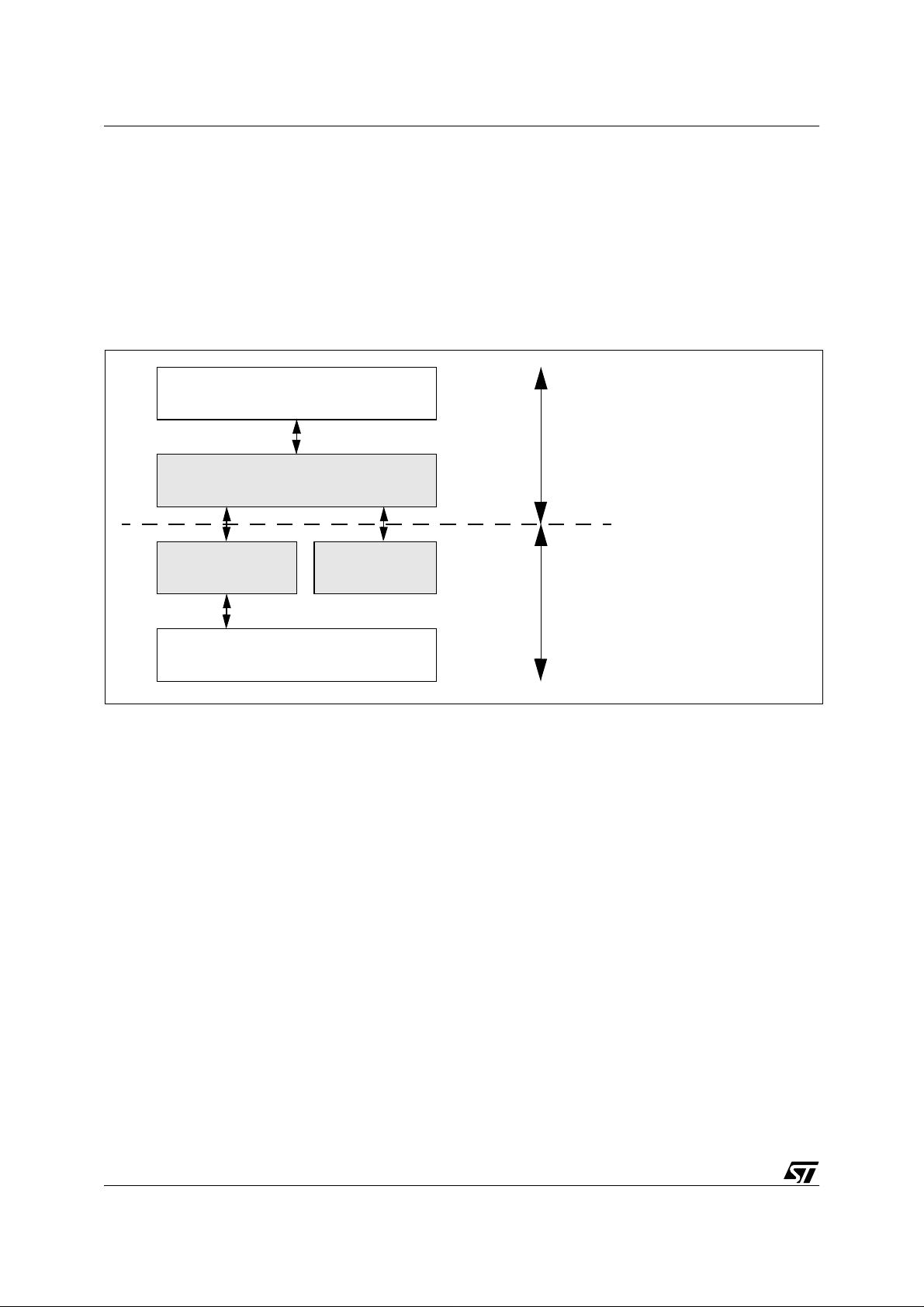
3.1 FIRMWARE ORGANIZATION
Both LS and FS projects are organized in the same way in terms of their DFU implementation.
Figure 1 shows the different software layers that have been added between the Lib rary and
the Application:
Figure 1. Firmware Overview
Application
Customer
DFU Protocol
DFU Core
Flash Driver
Example
STMicroelectronics
USB Library
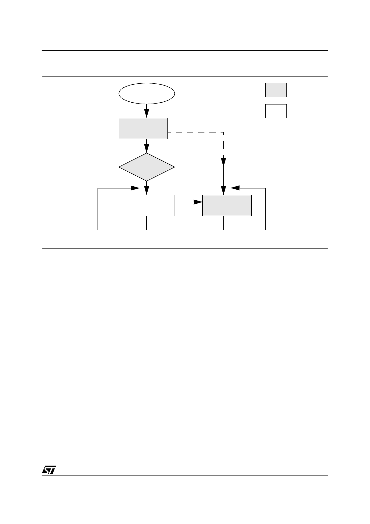
3.2 DFU MECHANISM
The solution proposed by STMi croelectron ics provides a mech anism for selecting entry into
DFU Mode (See Figure 2). To accomplish this task it is very important to understand that only
the Sectors 1 and 2 can be erased and programmed during DFU operation. Sector 0 contains
the USB Standard Library and the DFU class routines.
After MCU Reset, the Reset Vector points to the DFU main routine. Just afterward, a verification of the integrity of Sectors 1 and 2 is performed. T h is chec k c an be done in several ways:
Checksum, CRC, Code etc... If this test is OK (meaning that Sectors 1 and 2 are correct), then
the application main routine is executed. Otherwise the DFU process takes place.
There are two other ways to enter DFU mode:
1. By receiving a DFU_DETACH request while the application is running.
2. By Hardware after an MCU Reset. This solution allows the user to force entry into DFU
mode. This solution is only given as example and is i mplemented in the LS project onl y. It is
not described in the DFU specification.
8/30
Page 9
DEVICE FIRMWARE UPGRADE (DFU) IMPLEMENTATION IN ST7 USB DEVICES
Figure 2. DFU Mode Entry Mechanism
MCU Reset
Main DFU
Code, Checksum,
CRC, ...
Sectors 1 & 2
are OK ?
Yes
Main Application
3.3 FLASH SECTOR MANAGEMENT
Sector 0
Sectors
1 and 2
Forced DFU Mode Entry
(Controlled by har dware switch)
No
DFU_Detach
DFU Process
In order for the DFU mode entry mechanism described above to function correctly, it is necessary to place the firmware routines in the right sectors.
Basically, Sector 0 contains all routines that must be preserved during DFU erasing and programming. It principally contains the USB standard Library and the DFU layer routines.
Note: Application routines or constants can also be present in this sector, but in this case they
cannot be updated in DFU mode.
The Sectors 1 and 2 contain all routines and data that can be erased or changed in DFU
mode. They contain the Application routines and the “jump table” (see below).
The DFU_DETACH request decoding must also be present in these sectors. We can imagine
a “one shot DFU”, where the DFU_DETACH request decoding is not implemented in the new
firmware just downloaded (softw are protection) . The only way to recover is by using a H ardware switch (see Figure 2).
3.3.1 SECTOR 1 AND 2 INTEGRITY CHECK
As we have seen previously, we need to check if Sectors 1 and 2 are correct before calling the
main application routine. This will insure that these sectors are not corrupted due bad erasing
or bad programming. This check is not described in the DFU specification. and it can be easily
removed from the DFU protocol.
9/30
Page 10

DEVICE FIRMW ARE UPGRADE (DFU) IMPLEMENTAT ION IN ST7 USB D EVICES
In the LS project, the solution adopted for this check is the following:
- the last byte of sector 1 is reserved.
- after the erasing operation this byte contains FFh.
- at the end of downloading this byte is written with 6Dh.
- after each MCU Reset this byte is checked. If it contains 6Dh we jump to the Applic ation main
routine, otherwise we jump to the DFU process routine.
So, if the download operation is aborted or if something wrong happens the MCU will always
enumerate in DFU mode.
In the FS project a Checksum calculation is used:
- during downloading the Checksum is calculated on all the data received.
- at the end of download the Checksum is written at the end of Sector 1.
- after MCU Reset the Checksum is re-calculated and compared to the value written in the last
bytes of Sector 1.
Note: This second solution takes more execution time than the first one.
3.3.2 LIBRARY FUNCTIONS CALLED BY THE APPLICATION
The Application calls several functions from the USB Library.
For the LS project the Library functions called are:
Init_USB_HW, Di sable_USB_HW, Handle_U SB_Events, Enable_ST ATUS_Stage,
Test_EP_Ready, Set_EP_Ready, Write_EP_Buffer, Read_EP_Buffer.
These Library routines are placed in Sector 0 and their content and address locations are not
changed in DFU mode. The problem we face is that the Application firmware is also linked with
these Library routines. The location of these Library routines can be different from the location
chosen by the linker when the Library is compiled on its own...
A simple way to solve this issue is to access the Library functions using their direct address.
LS project example:
#define Init_USB_HW ((void(*)(void)) 0xF635)
The call to the function remains the same:
Init_USB_HW();
Special case: Functions with Parameters
Some Library routines need parameters with a number of bytes greater than 2. These are:
In the LS project: Set_EP_Ready, Write_EP_Buffer, Read_EP_Buffer .
10/30
Page 11

DEVICE FIRMWARE UPGRADE (DFU) IMPLEMENTATION IN ST7 USB DEVICES
If the MetroWerks compiler is used, the third and any subsequent bytes are saved in the
Overlap ar ea. Howe ver, this is not com patible w ith DFU op eratio n, becaus e the same area
could be used by a new application firmware (See RAM management for more details).
For these routines the parameters are passed through a structure of global variables.
LS project example:
#define Set_EP_Ready(EndPointPrm,DirectionPrm,LengthPrm) {\
GParams.SEPRParams.EndPoint=EndPointPrm;\
GParams.SEPRParams.Direction=DirectionPrm;\
GParams.SEPRParams.Length=LengthPrm;\
Set_EP_Ready_NP(); }
#define Set_EP_Ready_NP ((void(*)(void)) 0xF70E)
In the Application firmware we still use the same call to the Library routine:
Set_EP_Ready(0, EP_IN, 8);
But here the 3 parameters are saved in RAM. Then the Set_EP_Ready_NP routine is called.
The purpose of this routine is to retrieve the parameters previously saved in RAM and then to
call the Library routine located in Sector 0:
void Set_EP_Ready_NP (void) {
Set_EP_Ready(GParams.SEPRParams.EndPoint,GParams.SEPRParams.Direction,GParams.SEPRParams.Length);
}
Note: In the FS project, none of the Library functions use parameters. So, the issue does not
occur in this project.
3.3.3 APPLICATION FUNCTIONS CALLED BY THE LIBRARY
Also called ‘Call-back’ functions.
The Application routines called by the Library can have their address location changed after a
download. The address of these routines must be saved somewhere in order to allow the Library to call them. This area is called a ‘Jump Table’ (see below for details).
The Application functions called by the Library are:
In the LS and FS projects:
- the main application routine
- all the interrupt routines
In the LS project:
- the MCU_Init routine called when an USB EndSuspend interrupt occurs
- the USB spe cific routin es A ppli_S tat us_In and A ppli _Stat us_ Out fo r eac h Sta tus IN /OU T
stage
11/30
Page 12

DEVICE FIRMW ARE UPGRADE (DFU) IMPLEMENTAT ION IN ST7 USB D EVICES
In the FS project: all USER_USB_xxx functions.
3.3.4 JUMP TABLE
As already mentioned, this table is us ed to st ore the addres s of the Appli cation routines c alled
by the Library.
In the LS project: In order to use fewer bytes (when routines are called) this table is defined in
assembly. It simply contains a JP to the routine address.
This table is placed at a fixed address at the end of Sector 1: EFC0h
It is important to note that two assembly fil es are used for this Jump Table. One i s us ed during
the compilation of the Library in Sector 0, and contains dummy addresses. The second one is
used during the compilation of the Application in Sectors 1 and 2. A t this time the addresses
of the routines are known.
In the FS project: the call is performed in C language directly using a double function call.
Dummy functions placed at a fixed address are used for this purpose.
FS project example: The Library calls the USER_USB_Setup function. This function calls the
dummy function Vec_USB_Setup. It is located at a fixed address and it in turn calls the application function App_USB_Setup.
3.4 RAM MANAGEMENT
3.4.1 SHARED VARIABLES
Some variables are accessed by both Library and Application functions. These variables are
located at a fixed addresses in 16-bit RAM.
Some variables used:
In the LS project: UsbLibStatus, USBbReque st, USBwValue, USBwIndex, etc...
In the FS project: EPs_DataAddress, EPs_Length, etc...
The EndPoint buffers are also shared variables.
The location of these variables is done using pragmas or using the “@” symbol after the variable declaration.
3.4.2 LOCAL VARIABLES
This refers to all variables which are not shared between the Library and the Application functions. Library variables and Application variables are located in different areas in order to
avoid overlapping when an application firmware is upgraded. See the PRM files for details on
the location of these variables.
12/30
Page 13

DEVICE FIRMWARE UPGRADE (DFU) IMPLEMENTATION IN ST7 USB DEVICES
3.4.3 OVERLAP AREA
The Overlap area is not us ed by the L ibrary of the FS proj ect. So no precautions are n eces sary for this project.
But the Library of the LS project is strongly impacted. A lot of Library functions have parameters. When more than 2 b ytes ar e used, the parameter pass ing is done through the Overlap
area. An overlapping problem can occur when a firmware is upgraded. See the ex ample
below:
Initial state: the linker has placed a variable used by the application at address 50h and a variable used by a Library function at address 51h. The Library and Application firmware are
written in Sectors 0, 1, 2 using an EPB programming board:
Figure 3. Initial State of Overlap area prior to DFU
FLASH memory
Application 1
(sectors 1 & 2)
RAM memory (Overlap area)
50h
51h
Library
(sector0)
The problem appears when a new application firmware is written in the Flash and the overlap
area is modified. Suppose now that the application function uses a second variable. The linker
will locate this second variable at address 51h and the Library function variable at address
52h. But in DFU programming, the Library in Sector 0 is not changed and still uses the address 51h:
13/30
Page 14

DEVICE FIRMW ARE UPGRADE (DFU) IMPLEMENTAT ION IN ST7 USB D EVICES
Figure 4. Problem of Overlap area conflict after DFU
FLASH memory
Application 2
(sectors 1 & 2)
RAM memory (Overlap area)
50h
problem
51h
52h
Library
(sector0)
So, it is necessary also in this case to separate the Librar y and the Application Overlap areas.
Note: The same thing must also be done for the ZeroPage area. Refer to the project PRM file
for details about the location of these areas.
3.4.4 STACK
The stack area is shared by the L ibrary and the A pplication. N o special precautions are
needed in normal mode, but a minimum amount of free stack must be available before calling
any of the Embedded Commands used for HDFlash programming. This is explained in detail
further on.
3.5 DESCRIPTORS
3.5.1 STANDARD DESCRIPTORS
The normal run-time descriptors have to be modified to support DFU capability.
Device descriptor
The Product ID m ust be change d because wh en DFU is im plemente d, the devic e become s
composite.
In the LS project: Evaluation Kit + DFU has the number FF03h (instead of 0003h for Evalua-
tion Kit alone)
In the FS project: 5-in-1 + DFU has the number 0320h (instead of 1307h for 5-in-1 alone).
Note: When the device is in DFU mode only, its Product ID is the number DF11h. This number
is common for any project with DFU support.
Configuration descriptor
The bNumInterfaces of each configuration that supports DFU must be incremented by one.
For LS project: bNumInterfaces = 2 (HID + DFU)
For FS project: bNumInterfaces = 2 (MASS STORAGE + DFU)
14/30
Page 15

DEVICE FIRMWARE UPGRADE (DFU) IMPLEMENTATION IN ST7 USB DEVICES
Furthermore, 2 additional d escriptors must be ad ded at the end of the Configuration de scriptor: the Run-Time DFU Interface descriptor and the Run-Time DFU Functional descriptor.
These descriptors are described in detail below.
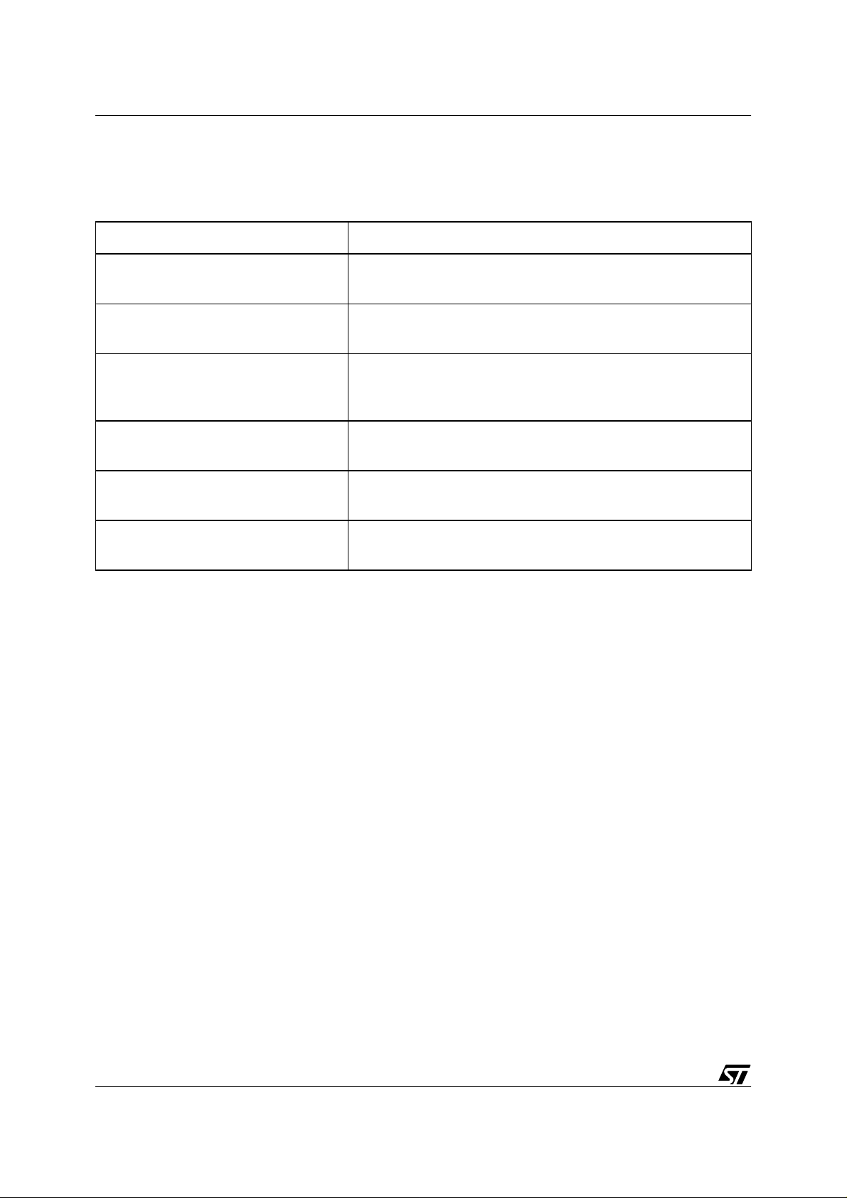
3.5.2 DFU DESCRIPTORS
The table below summarizes the 5 DFU descriptors to be created and in which mode they appear:
Table 2. DFU Descrip tors
Name Run-Time Mode DFU Mode
DFU Device Descriptor X
DFU Configuration Descriptor X
DFU Interface Descriptor X (**)
DFU Run-time Interface Descriptor X (*)
DFU Functional Descriptor X (*) X (**)
(*) Descriptor included in the Run-Time Configuration descriptor
(**) Descriptor included in the DFU Mode Configuration descriptor
These descriptors are placed in Sector 0 in the following files:
In the LS project: DFUDescript.c, DFUDescr ipt.h
In the FS project: DFU_desc.c
3.5.3 DFU STRING DESCRIPTORS
DFU string desc riptors a re i n th eoretically op tio nal. Bu t three desc riptors are created for the
DFU in the LS and FS projects. These allow the host to get some useful information when
Sectors 1 & 2 are incorrect.
DFU Language ID: 0409h (US English code)
DFU Manufacturer Name: STMicroelectronics
DFU Product Name: DFU Dem o
These descriptors are located in Sector 0 in the same files as listed above.
15/30
Page 16

DEVICE FIRMW ARE UPGRADE (DFU) IMPLEMENTAT ION IN ST7 USB D EVICES
3.6 PROTOCOL
3.6.1 DOWNLOAD STRATEGY
The strategy adopted in the LS and FS projects is exactly the same:
1) Sector 1 and/or Sector 2 are erased.
2) Blocks of data are transferred and progr ammed: 8 bytes for LS project and 128 bytes for the
FS project.
3) A code or a checksum is written at the end of Sector 1. This code certifies that the download
operation has been performed correctly.
The Host selects the data to be dow nloaded into the device. In order to dec rease the do wn loading time, blocks of data containing only FFh are not transferred. To achieve this strategy
the wBlockNum field of the DFU_DNLOAD request is used.
3.6.2 wBLockNum VALU ES
As already mentioned, this field is used to pass certain information during download. The
same field is also used in the DFU_UPLOAD request to read the flash memory. The table
below summarizes the values used:
Table 3. wBlockN um values
wBlockNum Description
FFFFh Erase Sectors 1 and 2
FFFEh Erase Sector 1 only
FFFDh Erase Sector 2 only
FFF C t o 1E000h Not Used
1DFFh to 1000h Flash address divided by 8
0FFFh to 0000h Not Used
Note: The fact that the Flash address is given divided by 8 is only a protocol example.
3.7 HARDWARE CONSIDERATIONS
3.7.1 VPP
The HDFlash memory needs 12V on the Vpp pin during erasing and programming operations.
This 12V is provided using a ST662A device. This device is al ready pres ent on the Evaluation
16/30
Page 17

DEVICE FIRMWARE UPGRADE (DFU) IMPLEMENTATION IN ST7 USB DEVICES
Kit and the 5-in-1 boards. A specific I/O port is used to control the presence of the 12V on the
Vpp pin:
LS project: I/O Port PB1
FS project: I/O Port PE4
Please re fer to th e “ST7 F am ily F las h P ro gram mi ng Ref eren ce Manual” for im plem e ntati on
details concerning the ST662A device.
3.7.2 FORCED DFU MODE ENTRY
In the LS project only, there is a possibility to enter DFU mode directly without checking the integrity of Sectors 1 & 2. To do this, the S W1 Swi tch must be press ed while the Res et button
is released. This mechanism is very useful when a problem occurs in the Application and the
DFU_D ETAC H com ma nd cann ot be inter prete d. If thi s happ ens in the FS pro ject, th e onl y
way to recover is to erase Sector 1 using an EPB programming board.
3.8 HDFLASH DRIVERS
Erasing and programming the HDFlash memory is d one using the Embedded Commands in
the System Memory of the ST7 device.
Some routines (drivers) have been created to access these Embedded Commands easily.
These routines can be used in any project that needs to erase or program the HDFlash.
For more information on these drivers see the AN1576.
3.8.1 FUNCTIONS USED
Only few driver functions are used in the DFU project. They are:
RASS_Disable: to unlock the FCSR register
HDFlashEraseSector: to erase a sector
HDFlashWriteByte: to write a single byte
HDFlashWriteBlock: to write a block
Note: The FS project uses the WriteBlock function to pr ogram the bytes into the Flash, while
the LS project uses the WriteByte function.
3.8.2 STACK AND RAM
Caution: Before launching any Embedded Command, the Stack Pointer must be greater than
or equal to 017Ch. This is due to the fact that 124 bytes are used in the Stack by the Embedded commands.
In the LS project, the Stac k area of the ST72F62 and ST 72F63B dev ices contains only 128
bytes. So, we must have a maximum of 2 function calls (starting from the main routine) before
17/30
Page 18

DEVICE FIRMW ARE UPGRADE (DFU) IMPLEMENTAT ION IN ST7 USB D EVICES
launching a HDFlash function. This limitation does not exist in the FS project because the
Stack area is bigger in the ST72F65 device.
Embedde d com mands also u se the R AM from F0h t o FFh fo r parame ter pa ssing a nd loca l
variables. This area must not be used by the application while the Embedded commands are
running.
18/30
Page 19

DEVICE FIRMWARE UPGRADE (DFU) IMPLEMENTATION IN ST7 USB DEVICES
4 DFU LOW-SPEED PROJECT
The LS DFU project ha s been crea ted sta rting fro m the ST7 U SB LS Ev aluati on Kit proj ect
and the ST7 USB LS Library. Two other parts have been added: the DFU specific files and the
HDFlash drivers (in bold in the next section).
4.1 DIRECTORIES
ST7USBLS-DFU
+-- EvalKit: ST7 USB LS Evaluatio n Kit project
+-- Config: project configuration files (mak, prm, etc...)
+-- Appli: application files
+-- DFU: DFU layer fil es
+-- Objects: output from compilat ion
+-- HDFlashDriver: Fla sh routines to erase and program
+-- Library: ST7 USB LS Library p roject
+-- Config: project configuration files (mak, prm, etc...)
+-- Macro: macros definitions
+-- Micro: devices mapping files
+-- Usb: ST7 USB Low-Speed Librar y kernel files
+-- Objects: output from compilat ion
As you can see the Library can be compiled alone without the EvalKit project. This is because
the RAM area of the Library i s c ompletely separated fr om the RAM area of the EvalKit pr oject.
So, a different prm file is needed. The S19 file generated from the Library can then be loaded
into Sector 0 even if the EvalKit project is not ready.
4.2 DFU FILES
All these files are placed inside the “DFU” directory. Files in bold ar e files that depend on the
protocol and/or the application, and may be modified by the user.
19/30
Page 20

DEVICE FIRMW ARE UPGRADE (DFU) IMPLEMENTAT ION IN ST7 USB D EVICES
Table 4. LS Project DFU Files
File Name Description
DFUCore.c / DFUCore.h
DFUDescript.c / DFUDescript.h
DFUJumpTable_XXX.asm
DFULibFuncAdd.h
DFUProtocol.c / DFUProtocol.h
Contain the DFU Kernel routines. Not protocol nor application dependant.
Contain the DFU descriptors. They are dependant on the application.
Contain the Jump Tables used by the Library to access the
application routines. Dependant on the application.
Contain the address of the Library routines called by the Application. Must be modified each time the Library function addresses are changed.
Contain the DFU protocol routines. They are dependant on
the application.
4.3 DFU CALL-BACK FUNCTIONS
These functions a re called by th e DF U Kernel routines . They are dependa nt on the pr otocol
and/or the application. All these functions are located in the “DFUProtocol.c” file. The content
of these functions is only a DFU implementation example. Depending on the protocol adopted,
these functions can be modified by the user.
Table 5. LS Project DFU Call-back Functions
Function Name Description
DFU_Abort_User
DFU_ClearStatus_User
DFU_Download_User
DFU_Init_User
20/30
Called by the DFU_Abort function when a DFU_ABORT request is received. Used to set Vpp to 5V.
Called by the DFU_ClearStatus function when a
DFU_CLRSTATUS request is received.
Called by the DFU_Download function when a
DFU_DNLOAD request is received. Used to received and
decode the data from the Host.
Called by the DFU_Init function when entering DFU mode.
Used to initialize variables, Vpp, etc...
Page 21

DEVICE FIRMWARE UPGRADE (DFU) IMPLEMENTATION IN ST7 USB DEVICES
Table 5. LS Project DFU Call-back Functions
Function Name Description
Called by the DFU_GetStatus function at the end of the
DFU_ManifestWaitReset_User
downloading phase. This function is used to write the End Of
Programming code in the last byte of Sector 1.
DFU_S1S2Valid
DFU_UpLoad_User
HDFlashProcess
VbusCheck
Used to check the integrity of Sectors 1 and 2. This is the first
function called by DFU_Main after Reset.
Called by the DFU_Upload function when a DFU_UPLOAD
request is received. Used to prepare and send the data to the
Host.
Called by the DFU_Main function. This function manages the
call to all HDFlash routines.
Used to check the presence of the Vbus when device is in
self-powered mode. This function is compiled if the
SELF_POWERED compi lation variable is defined.
4.4 OTHER DFU FUNCTIONS
These function s are n ot called b y the Library. They are uti lity routin es used during DFU
processing.
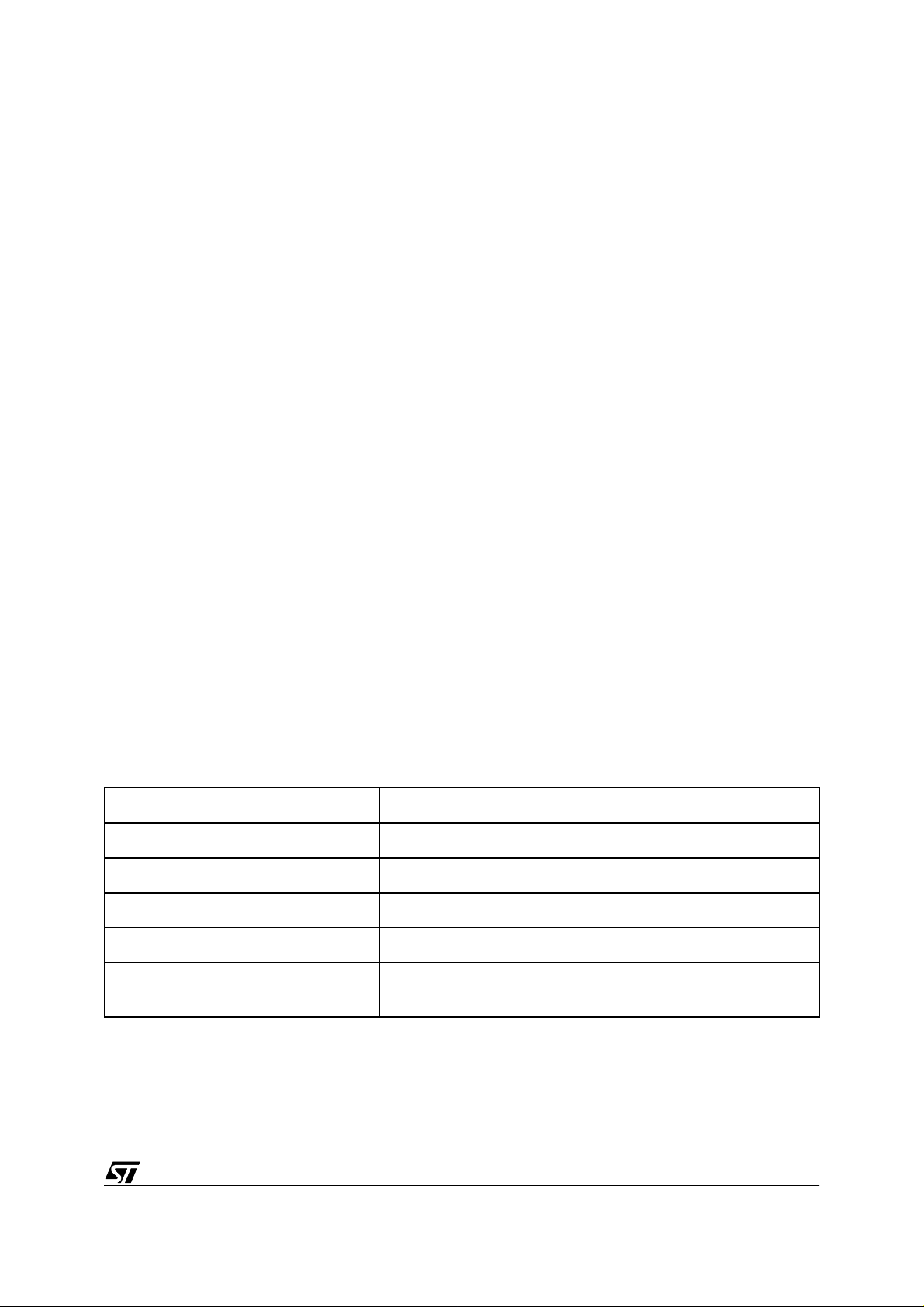
Table 6. LS Project Other DFU Functions
Function Name Description
SetVpp12V
SetVpp5V
Used to set the Vpp voltage to 12V needed during erasing or
programming operations.
Used to set the Vpp Voltage to 5V when not erasing or programming.
4.5 DFU VARIABLES
These variables are shared by the DFU kernel and the DFU protocol functions.
21/30
Page 22
DEVICE FIRMW ARE UPGRADE (DFU) IMPLEMENTAT ION IN ST7 USB D EVICES
Table 7. LS Project DFU Variable
Variable Name Description
DFUDataReceived
DFUDataToSend
DFUDeviceState
DFUDeviceStatus
DFUPo llTimeOutH
DFUPollTimeOutL
Buffer for storing data coming from the host after a DownLoad request.
Buffer containing data to send to the host for UpLoad, GetState or GetStatus requests.
Contains the current DFU state of the device as defined in the
DFU specification. Sent after a GetState or GetStatus request.
Contains the current DFU status of the device as defined in
the DFU specification. Sent after a GetStatus request.
Contains the high byte of the Polling TimeOut. Sent after a
GetStatus request.
Contains the low byte of the Polling TimeOut. Sent after a
GetStatus request.
4.6 RESTRICTIONS
This project is compatible with MetroWerks compiler only and with ST72F62-16K and
ST72F63B-16K devices due to RAM size restriction.
22/30
Page 23
DEVICE FIRMWARE UPGRADE (DFU) IMPLEMENTATION IN ST7 USB DEVICES
5 DFU FULL-SPEED PROJECT
The FS DFU project has been created from the ST7265 5-in-1 project and the ST7 USB FS Library. Two other parts hav e been added: the DFU specific files and the HDFlash drive rs (in
bold in the next section).
5.1 DIRECTORIES
ST7USBFS-DFU
+-- Object: output from compilati on
+-- Sources
+-- MassSto
+-- Mcl
+-- Usb: ST7 USB Full-Speed Library kernel files
+-- Usb_App: USB application specific files
+-- Usb_DFU: USB DFU specific files (kernel + application + HD Flash drivers)
For details of “MassSto” and “Mcl” directories please refer to AN1475 “Developing an
ST7265X Mass Storage Application”.
5.2 DFU FILES
All these files are l ocated in the “ Usb_DFU” directory. F iles in bol d ar e fi l es that depend on the
protocol and/or the application, and can be modified by the user.
Table 8. FS Project DFU Files
File Name Description
DFU.c / DFU.h Contain all DFU kernel and Protocol routines.
DFU_Desc.c Contains the DFU descriptors.
DFU_Var.asm Contains the definition of DFU variables.
Flashing.h Contains the HDFlash routines.
User_USB.c / User_USB.h
Contain all call-back functions called by the Library. These
functions call the DFU functions described in the DFU.c file.
23/30
Page 24
DEVICE FIRMW ARE UPGRADE (DFU) IMPLEMENTAT ION IN ST7 USB D EVICES
5.3 DFU CALL-BACK FUNCTIONS
These functions are not directly called by the Library. Instead they are called by intermediate
layer functions like “USER_USB_Reset”, etc... They are protocol and application dependant,
and you can modify them to fit with yours application/protocol.
Table 9. FS Project DFU Call-back Functions
Function Name Description
Used to check if the Application code in Sectors 1 and 2 is
DFU_App_Valid
valid. A Checksum is calculated and compared with the
Checksum previously saved in the last bytes of Sector 1. Returns 0 if Checksum is false.
DFU_Status_In
DFU_Status_Out
DFU_CopyDataIN Not used in this project.
DFU_CopyDataOUT
DFU_Setup Used to decode and process all DFU requests.
Processes some of the DFU OUT requests during the Status
stage. For example DownLoad and Detach.
Processes some of the DFU IN requests during the Status
stage. For example UpLoad and GetStatus.
Used to copy data returned by a DownLoad request into the
EndPoint 0 Out buffer.
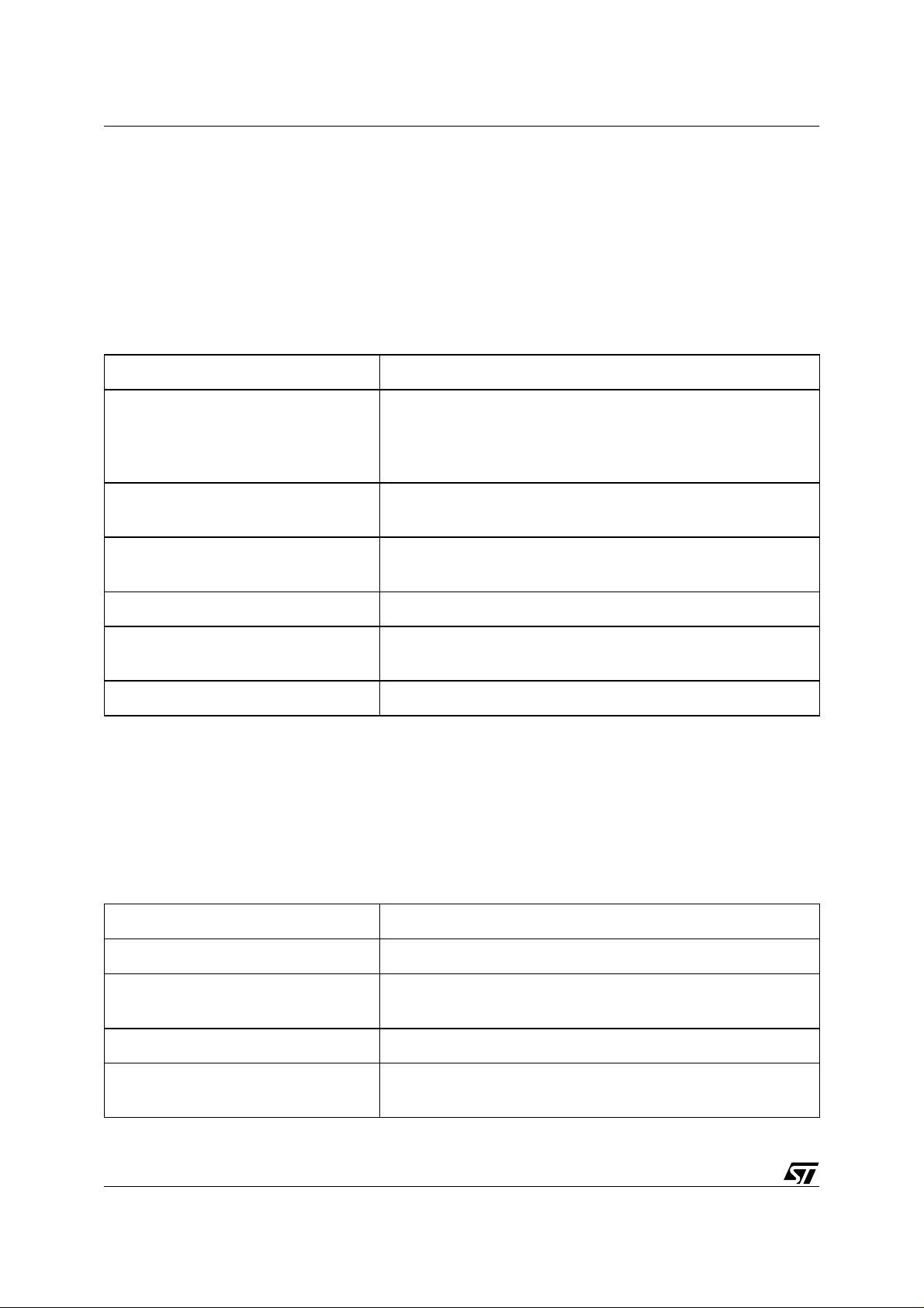
5.4 OTHER DFU FUNCTIONS
These functions are not call-back functions. They are u tility routines used during DFU
processing.
Table 10. FS Project Other D FU Functions
Function Name Description
CheckSum_ROM Used to calculate a checksum on Sectors 1 and 2.
CRC_ROM
DFU_Init Used to initialize all DFU variables.
DFU_Manifest
24/30
Used to calculate a CRC on Sectors 1 and 2. Not used in this
project, only given as example.
Called after Downloading is finished. Calculates and writes
the Checksum in the Flash.
Page 25

DEVICE FIRMWARE UPGRADE (DFU) IMPLEMENTATION IN ST7 USB DEVICES
Table 10. FS Project Other D FU Functions
Function Name Description
Flashing_End Sets Vpp to 5V. Called when Flash operations are finished.
Flashing_Start
Jmp_Label
Replug_Device
Set_Label
Setup_Timer
5.5 DFU VARIABLES
Table 11. FS Project DFU Variables
Variable Name Description
Sets Vpp to 12V and unlock FCSR register. Called before
Flash operations start.
Jumps to the address previously saved by the Set_Label
function.
Powers down and Power up the USB voltage regulator to
simulate a replug to the Host. Used after a Detach and after
programming is finished.
Saves current PC in a variable. This variable is used to jump
to the right place after a Detach request for example.
Initializes the timer used to count the timeout value after a
Detach request is received.
DFU_Action Used to keep trace of the current DFU action.
DFU_BlockNum
DFU_BlockSiz Contains the number of bytes to program or read.
DFU_Buffer
DFU_Capability Contains information on DownLoad and UpLoad capabilities.
DFU_Request Contains the current DFU request received.
DFU_State
DFU_Status Contains the current DFU Status. Sent by GetStatus request.
DFU_Timeout Contains the TimeOut value sent by Detach request.
Contains the wBlockNum value present in DownLoad and
UpLoad DFU requests.
Used to store the data received from the Host (DownLoad request) or to send to the Host (UpLoad request).
Contains the current DFU State. Sent by GetState and GetStatus requests.
25/30
Page 26

DEVICE FIRMW ARE UPGRADE (DFU) IMPLEMENTAT ION IN ST7 USB D EVICES
5.6 RESTRICTIONS
This project is compatible with MetroWerks compiler and with the ST72F65 device only.
26/30
Page 27

DEVICE FIRMWARE UPGRADE (DFU) IMPLEMENTATION IN ST7 USB DEVICES
6 RELATED DO CUMENTS
Table 12. External Docu ments
Name Version/Date
Universal Serial Bus Specification
Universal Serial Bus Device Class Specification for Device
Firmware Upgrade
1.1
Sept 23, 1998
1.0
May 13, 1999
Table 13. STM Documen ts
Name
ST7 Family Flash Programming Reference Manual
AN1575 “On-Board Programming Methods for XF lash an d HDF lash ST7 MC Us”
AN1576 “In-Application Programming Drivers for XFlash and HDFlash ST7 MCUs”
AN1475 “Developing a ST7265X Mass Storage Application”
AN1603 “Using the ST7 USB Device Firmware Upgrade Development Kit (DFU-DK)”
ST7 USB Device Firmware Upgrade Dem onstrator User Manual
27/30
Page 28

DEVICE FIRMW ARE UPGRADE (DFU) IMPLEMENTAT ION IN ST7 USB D EVICES
7 RELATED SOF TW AR E
Table 14. Microcontroller Software
Name Description
This is the example referred to in this application note
(AN1577) of a user application firmware with DFU capabil-
ST7 USB Full Speed DFU Project:
DFU for ST72F65x devices
ST7 USB Low Speed DFU Project:
DFU for ST7262/63B devices
Table 15. PC Software
ity for the ST72F65x devices. The project is supplied as a
zip file containing all the necessary source and project files
ready for compilation by the Metroworks C Complier. It can
be used to test the DFU process and can be easily adapted by the user to another application.
This is the example referred to in this application note
(AN1577) of a user application firmware with DFU capability for the ST72F62 or ST72F63B devices. The project is
supplied as a zip file containing all the necessary source
and project files ready for compilation by the Metroworks
C Complier. It can be used to test the DFU process and
can be easily adapted by the user to another application.
Name Description
ST7 DFU Demo Package
DFU-DK Development Kit Package
This an example of a Graphical User Interface for starting
a DFU session. It can be used with the ST7 USB Full
Speed and Low Speed Projects listed in Table 14 or with
any user-developed project that uses the same protocol. It
has been developed in Visual C++ and is supplied as an
installation file ready to be installed on a Windows PC.
This a set of library routines and device drivers that can be
used to develop a Windows GUI application such as the
ST7 DFU Demo Package listed above. Refer to AN1603
for more information.
28/30
Page 29

DEVICE FIRMWARE UPGRADE (DFU) IMPLEMENTATION IN ST7 USB DEVICES
8 TERMS AND ABBREVIATIONS
Table 16. Terms and Abbreviations
Term Definition
DFU Device Firmware Upgrade
Firmware
Executable software stored in a write-able, nonvolatile memory on a USB device
(1) To overwrite the firmware of a device, (2) the act of over-
Upgrade
writing the firmware of a device, (3) new firmware intended to
replace a device’s existing firmware
Download To transmit information from host to devic e
Upload
LS project
To transmit information from device to host
Low Speed Evaluation Kit project ( for ST72F62 and 72F63B
devices)
FS project Full Speed 5-in-1 board project (for ST72F65 device)
29/30
Page 30

DEVICE FIRMW ARE UPGRADE (DFU) IMPLEMENTAT ION IN ST7 USB D EVICES
“THE PRESENT NOTE WHICH IS FOR GUIDANCE ONLY AIMS AT PROVIDING CUSTOMERS WITH
INFORMATION REGARDING THEIR PRODUCTS IN ORDER FOR THEM TO SAVE TIME. AS A RESULT, STMICROELECTRONICS SHALL NOT BE HELD LIABLE FOR ANY DIRECT, INDIRECT OR
CONSEQUENT IAL DAMAGES WI TH RESPECT TO ANY CLAIMS ARIS ING FROM THE CONTENT OF
SUCH A NOTE AND/OR THE USE MADE BY CUSTOMERS OF THE INFORMATION CONTAINED
HEREIN IN CONNECTION WITH THEIR PRODUCTS.”
Information furnished is believed to be accurate and reliable. However, STMicroelectronics assumes no responsibility for the consequences
of use of such information nor for any infringement of patents or other rights of third parties which may result from its use. No license is granted
by implic ation or otherwise under any patent or patent r i ght s of STMi croelectr oni cs. Spec i fications mentioned i n this publication are subject
to change without notice. This publication supersedes and replaces all information previously supplied. STMicroelectronics product s are not
authorized for use as cri tical comp onents in lif e support devi ces or systems without the express written appr oval of STMic roelectronics.
The ST logo is a registered trademark of STMicroelectronics
2003 STMicroelectronics - All Rights Reserved.
STMicroelectronics Grou p of Companies
http://www.s t. com
Purchase of I
2
C Components by STMicroelectronics conveys a license under the Philips I2C Patent. Rights to use the se components in an
2
C system i s granted pro vi ded that the sy stem conforms to the I2C Standard Specification as defined by Philips.
I
Australi a - Brazil - Canada - China - Fi nl and - Franc e - Germany - Hong Kong - Ind i a - Is rael - Ital y - J apan
Malaysi a - M al ta - Morocco - Singapore - Spain - Sweden - Sw itzerland - Uni t ed Kingdo m - U.S.A.
30/30
 Loading...