

Page 1

AN1576
APPLICATION NOTE
IN-APPLICATION PROGRAMMING (IAP) DRIVERS
FOR ST7 HDFLASH OR XFLASH M CUs
by Microcontroller Division Applications
INTRODUCTION
The In-Application Programming (IAP) architecture defined by STMicroelectronics gives a
large flexibility in terms of the communication method used to (re)program a ST7 FLASH Microcontroller on bo ard: no t only the physica l chan nel (I/O s, SPI, U ART, USB, C AN,..) for receiving the new data, but also the protocol (Commands, Status, Data structure,..) can be user
specific.
The principle of the IAP pr ocess ( See Application N ote AN1575 for further d etails) i s to e xecute from a p rotected m e mory area, Flash S ecto r 0, a firm ware mo dule tha t reprogram s t he
remaining memory area: In order to help you dev elop you own reprogramming firmware,
STMicro elect ronics provid es gener ic IAP dr ivers that ca n be us ed what ever the p rotoc ol or
physical layer.
This application note presents these two generic In- Appl ication Programming drivers: one for
HDFLASH based MCUs and one for XFLA SH based devices.
The architecture and the software interfac e as well as s ome practi cal examples are presented
for each of these two drivers.
AN1576/0203 1/15
1
Page 2

XFLASH DRIVER
1 XFLASH DRIVER
The XFlash driver is a softw are which can be comp iled using either C -Metrowerks or CCOSMIC and supports all memory models.
The driver is composed of 2 files: XFlash.c and XFlash.h to be included in the project. It provides RASS_Disable, and XFlashWriteBlock functions. No
Sector Erase
since it can be emulated by writing 0xFF in a memory block.
The driver code i s approxim ately 256 by tes in size, this may vary slightly de pending on the
compilation.
1.1 DRIVER FUNCTIONS
1.1.1 RASS_Disable
void RASS_Disable(unsigned char key1,unsigned char key2)
This function disables the RASS protection to allow write access to XFLASH sectors 1 & 2, if
the two user variables key1 and key2 have the correct values: 0x56 and 0xAE.
To increase the reliability of the system, the software sequence which writes the hardware
keys should not be stored in the program mem ory. Both hardware keys must always be
loaded ext ernal ly (via I/O ports, SC I, e tc ...). Thi s s ec urity fe atu re p reve nts a ny w ron gfu l ac cess after a program counter corruption.
function is provided,
1.1.2 XFlashWriteBlock
unsigned char XFlashWriteBlock( unsigned char *Buffer, unsigned int Flash, unsigned char ByteNb )
This function performs write operations with the following parameters:
–
Buffer
–
Flash
–
ByteNb
points to the start address of the new data to be programmed
points to the XFLASH start address area where the new data is to be programmed
is the number of bytes to be programmed
The ByteNb can take a val ue of up to 256 ev en tho ugh the XF LA SH itself i s progr ammed in
rows of 32 bytes max: The XFLASH driver handles the iterative loops automatically in cases
where ByteNb is greater than 32.
The function returns a status: 0 means a failed operation, while a 1 means a successful operation.
2/15
2
Page 3

XFLASH DRIVER
1.1.3 User functions
The XFlash driver allow s use r specific functi ons to be ex ecuted w hile an XF lashW riteBl ock
function is executing. Writing 256 bytes requires several tenths of a millisecond during which
time you may have to manage some tasks: A typic al example is to refres h the watchdog , in
order to avoid a Reset during XFlash reprogramming.
For this purpose the driver provides 1 function named UserWhileWriteBlock that you have to
define in your firmware (take care to not use the RAM area with the driver variables).
Finally, the Interrupts are reenabled (RIM assembler instruction) by the driver before the execution of the UserWhileWrite function.
1.2 DRIVER ARCHITECTURE
1.2.1 Driver principle
When called by the user firm ware in Flash Sec tor 0, the Xf lashWrite Block executes the following sequence:
– Load the RAM Page 0 with a programming algorithm
– Execute this programming algorithm from RAM
– Return to the user firmware in Flash Sector 0, just after the XflashWriteBlock instruction.
At this point the RAM area used by the programming algorithm is released and is available to
the user firmware.
1.2.2 Memory management
The programming algorithm requires 20 bytes and is positioned at the end of RAM Page 0.
In addition, 7 bytes in RAM Page 0 are reserved for the IAP driver internal variables.
The location of the 27 bytes (algorithm plus variables) is defined in the Xflash.h file by the pa-
rameter STACK_END: The location is then 0xE4h-0xFFh for a S T72F264 M CU.
It is important to note these 27 bytes ar e used only during the XFlash WriteBlo ck execution:
You can still use this area in his application firmware (except in the UserWhileWriteBlock function) as long as he accepts they are overwritten during the IAP process.
3/15
Page 4
XFLASH DRIVER
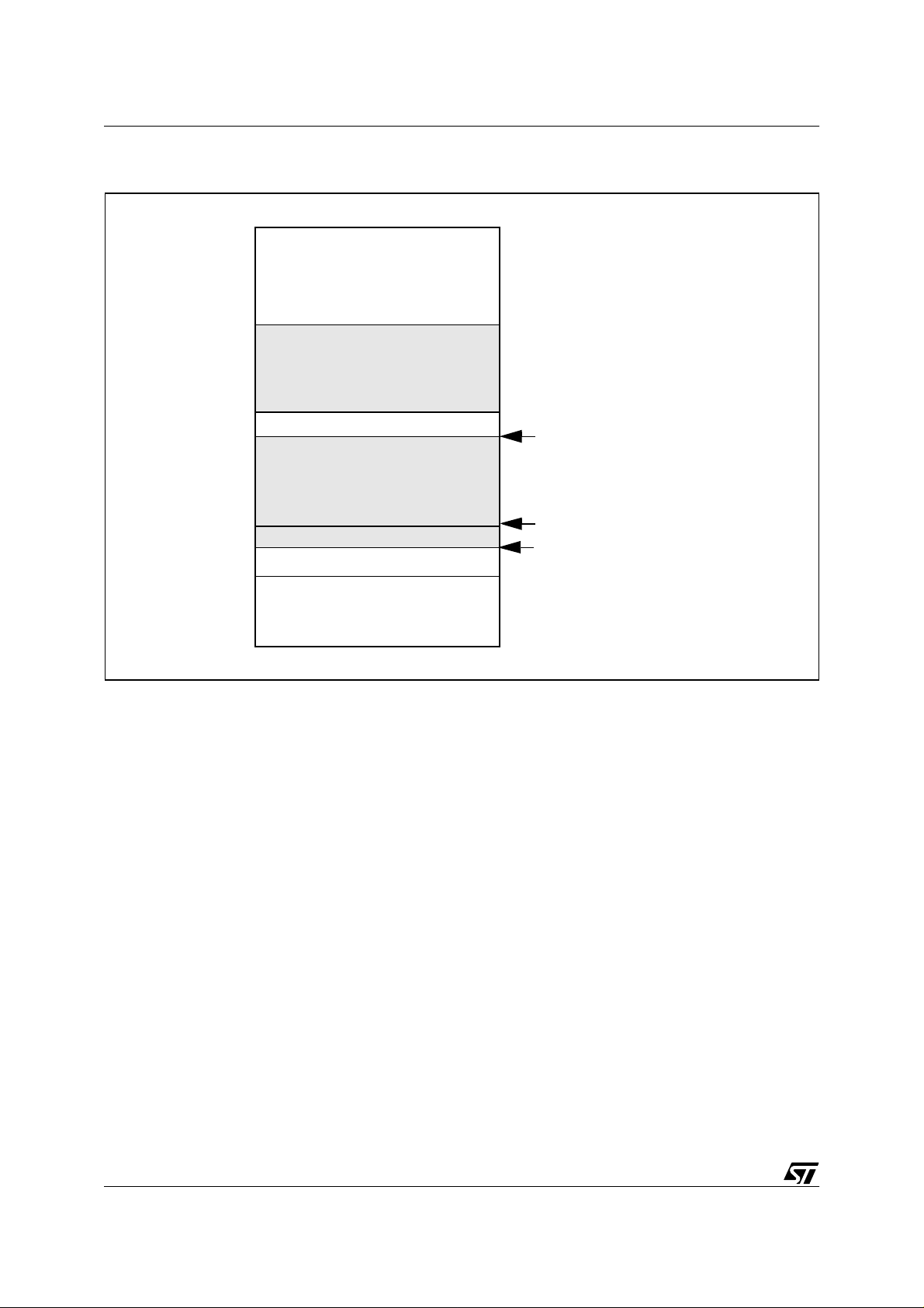
Figure 1. RAM usage with XFLASH driver: ST72F264 example
New data to be programmed
Page 0: 0xE4h
Programming algorithm
Page 0: 0xF8h
Driver internal variables
Page 0: 0xFFh
Stack
1.2.3 Interrupts
All the interrupt sources are disabled (SIM assembler instruction) by the XFlash driver.
4/15
Page 5
XFLASH DRIVER
1.3 IMPLEMENTATION GUIDELINES
An example is used to describe some generic guidelines you have to follow when developing
an application with IAP capability. It includes all the modules you need for an application with
IAP:
■ Reset and initialization routines
■ Basic user interface
■ Reprogramming routines (On external Interrupt)
■ Reprogrammable software module in sector 1
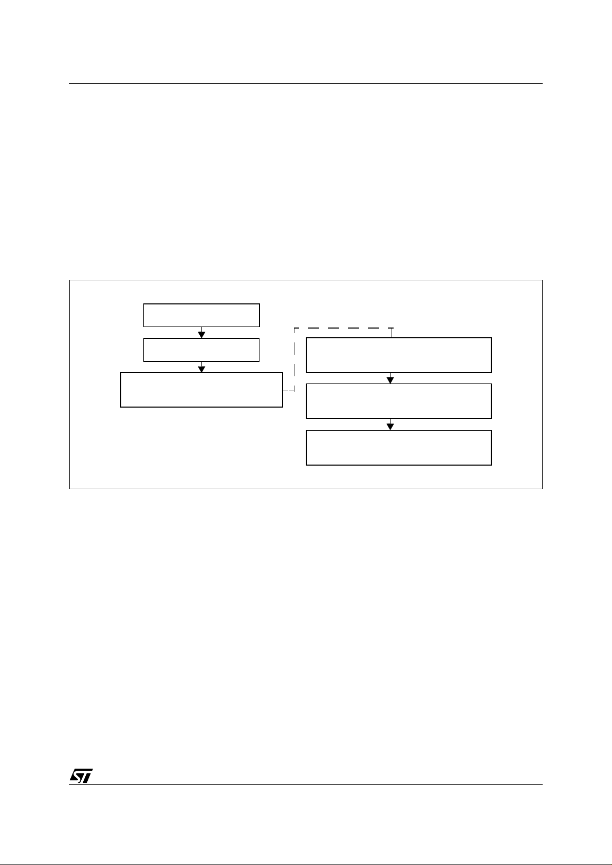
Figure 2. Example Flowchart
Begin
Initialization
External Interrupt
Load new program
from external EEPROM to buffer
Endless loop in sector1
Start programming phase
Software Reset
1.3.1 Project Configuration
1.3.1.1 Driver Configuration
The first step is to correctly configure the stack position in the Xflash.h file. This parameter is
defined by the variable STACK_END. The XFlash driver uses this value to address its internal
variables located at the top of RAM Page 0.
1.3.1.2 Program Memory
Special attention must be paid to the fact that some routines have to be executed from Sector
0 to ensure reliable operations.
Therefore pragmas have to be defined in such a way that Sector 0 includes: the XFlash driver,
the Reset, Initialization and UserWhileWriteBlock routines as well as any library routines
(Delay loops,..) needed for the reprogramming process.
5/15
Page 6

XFLASH DRIVER
1.3.2 RAM Management
1.3.2.1 New Code Buffer
It is recommended to define the buffer with the new code as a local variable at a fixed address
in RAM Page 0. This has two advantages:
– The memory area is released by the IAP process.
– There is no risk of data overlap with the other local variables handled by the compiler.
Finally, its size must be defined in or der to n ot conflict with the XF LAS H driver and i ts varia bles: Its maximum size is the n 128 -27= 1 01 bytes . In thi s examp le, a 64 by te size has been
chosen: The 128 bytes are programmed in two steps of 64.
1.3.2.2 Stack
One advantage of the XFLASH driver is that it does not use the stack: The XFlashWriteBlock
function can be called by the firmware without any special precautions, and uses local variables. Therefore a l ocal loop can be used to manage data ranges ov er the buffer s ize, as shown
in the example given in Section 1.3.3 .
6/15
Page 7

XFLASH DRIVER
1.3.3 Firmware template
#include "io72264.h"/* ST72264 memory and register mapping */
#include "Xflash.h" /* XFlash driver software */
void Loop(void);
/*************************Main loop ****************************************/
void main(void)
{
/************************ Initialization **********************************/
ST7_Init(); //General initialization
while(1) Loop();
}
/*****************UserWhileWriteBlock*************************************/
void UserWhileWriteBlock(void)
{
WDGCR=0x08; //Refresh WATCHDOG Timer
}
/***************Programming routine within External ISR*********************/
@interrupt void On_DEMO(void)
{
unsigned char tmp;
unsigned char RamBuffer [64]@0xA6; /* New code and RASS keys buffer */
SPI_Init(); //initialize SPI communication
SPI_Rx(RamBuffer,2,100,(char)0); //Receive RASS keys from EEPROM
RASS_Disable(RamBuffer[0],RamBuffer[1]); //Unlock Flash
for (tmp=0;tmp<2;tmp++)
{
SPI_Rx(RamBuffer,64,64*tmp,(char)0);
XFlashWriteBlock(RamBuffer,(unsigned int)&Loop+64*tmp,64);
}
SPI_Disable();
WDGCR=0xC0; //Resets the MCU which also relocks the XFLASH;
}
/************************Sector 1 software*********************************/
#pragma section (Loop)
void Loop(void)
{
}
7/15
Page 8

HDFLASH DRIVER
2 HDFLASH DRIVER
The HDFlash driver software can be compiled using C-Metrowerks or C-COSMIC.
The driver is composed of 2 files: HDFlash.c and HDFlash.h to be included in the project. In its
minimum conf iguration , it provides RASS_D isable, HDFlashW riteBlock and HDFlashEr aseSector functions. In th is confi guration, t he dri ver code is a pproximatel y 85 byt es in size, thi s
may vary slightly depending on the compilation.
However, the HDFlash.c file includes some other functions you can decide (#define) to use.
2.1 DRIVER FUNCTIONS
2.1.1 RASS_Disable
void RASS_Disable(unsigned char key1,unsigned char key2)
This function disables the RASS protection to allow write access to HDFLASH Sectors 1 & 2,
if the two user variables key1 and key2 have the correct values: 0x56 and 0xAE.
To increase the reliability of the system, the software sequence which writes the hardware
keys must not be stored in program memory. Both hardware keys must always be loaded externally (via I/O ports, SCI, etc...). This security feature prevents any wrongful acces s after a
program counter corruption.
2.1.2 HDFlashWriteBlock
HDFlashWriteBlock( unsigned char *Buffer , unsigned char *Flash, unsigned char ByteNb,unsigned char
Freq)
This function performs write operations with the following parameters:
–
Buffer
–
Flash
–
ByteNb
–
Freq
points to the start address of the new data to be programmed
points to the HDFLASH start address area where the new data is to be programm e d
is the number of bytes to be programmed
defines the programming pulse
The ByteNb can take a value of up 256 even though the HDFLASH itself is programmed byte
by byte: The HD FL AS H d river han dles t he i terative l oop s in ca ses whe re B y teNb is gr eate r
than 1.
This function returns a value 01 when successful
2.1.3 HDFlashEraseSector
HDFlashEraseSector(unsigned char Sector, unsigned char Freq)
This function performs the erase operations with the following parameters:
Sector
Freq
is the sector number (1 or 2)
.
is the internal frequency of the Microcontroller
8/15
Page 9

HDFLASH DRIVER
This function returns the value 03 when successful.
2.1.4 User functions
The HDFlash driver allows user specific functions to be executed during a HDFlashWriteBlock
or HDFlashEraseSector function. This these operations require several tenths of a millisecond
in during which you may have to manage some other tasks: A typical example is to refresh the
watchdog, in order to prevent a Reset while the HDFlash is being reprogrammed or erased.
For this pur po se th e driver prov ides 2 fu nctions na med Us erWh ileWr iteBloc k an d Use rWhileErase, that you have to define in your firmware.
2.1.5 Programming/Erasing Su pp ly Voltage Management
The HDFlash driver does not take into account the management of the external VPP supply.
This is becaus e th e VPP imp lementati on is total ly user spec ific and cannot be co vered by a
generic driver.
2.2 DRIVER ARCHITECTURE
2.2.1 Driver principle
The HDFlashWriteBlock function works as follows:
Once called by the user firmware in sector0, HDFlashWriteBlock and HDFlashEraseSector
execute the following sequence:
– Load the RAM memory at the current stack pointer with the programming algorithm
– Execute this programming algorithm from the RAM
– Return to the user firmware in sector 0, just after the HDFlashWriteBlock or HDFlashErase-
Sector instruction.
At that point the RAM area used by the programming algorithm is released and is available to
the user firmware.
Note that the stack pointer remains at the value before the HDFlashWriteBlock or H DFlashEraseSector call.
2.2.2 Memory management
The programming algorithm requires 124 bytes and is positioned at the current stack pointer:
Part of it can then be loaded into RAM Page 0 (Adjacent to the stack) in case the stack is already filled.
Take care that you have at l east 124 by tes free in the stack when calling the HDF lashWriteBlock functions. This condition can be satisfied by reducing the number of stacked “Calls” between the main loop and the HDFlashWriteBlock or HDFlashEraseSector function.
In addition, 16 bytes in RAM Page 0 (Sort addressing mode) are reserved for the IAP driver internal variables. Their location is 0xF0-0xFF and cannot be changed.
9/15
Page 10

HDFLASH DRIVER
Note: These variables are used only during HDFlashWriteBlock or HDFlashEraseSector exe-
cution: you can still use this area in your application firmware as long as you accept they may
be overwritten during the IAP process.
Figure 3. RAM usage with HDFLASH driver
New data to be programmed
Driver internal variables
Programming algorithm
End of stack
Stack pointer
Top of stack
10/15
Page 11

HDFLASH DRIVER
2.3 IMPLEMENTATION GUIDELINES
An example is used to describe some generic guidelines you should follow when developing
an application with IAP capability. It includes all the modules you need or an application with
IAP:
■ Reset and initialization routines
■ Basic user interface
■ Erasing & Reprogramming routines (On external Interrupt)
■ Reprogrammable software module in sector 1
Figure 4. Example Flowchart
Begin
Initialization
External Interrupt
Load new program
from external EEprom to buffer
Endless loop in sector1
Start programming phase
Software Reset
2.3.1 Project Configuration
2.3.1.1 Driver Configuration
There is n o nee d for driv er c on figu ration : Eac h MC U h as a n emb edded pr ogr am ming algo rithm already configured.
2.3.1.2 Program Memory
Be very careful that some routines have to be executed from Sector 0 to ensure reliable operations
Therefore pragmas have to be defined in such a way that Sector 0 includes: the HDFlash
driver, the Reset, Initialization, UserWhileErase and UserWhileWriteBlock routines as well as
any library routines (Delay loops,..) needed for the reprogramming process.
11/15
Page 12

HDFLASH DRIVER
2.3.2 RAM Management
2.3.2.1 New Code Buffer
The buffer with the new code must be defined outside the stack, and outside of the F0h-FFh
range.
In addtition , it i s reco mmen ded to defin e it a s a l ocal vari able a t a fixed addres s, which
presents a double advantage:
The memory area is released by the IAP process.
There is no risk of data overlap with the other local variables handled by the compiler.
2.3.2.2 Stack
As already stated, the HDFLASH driver occupies 124 bytes in the stack. This generally leaves
only 4 bytes free in RAM a nd limits the possib ility of using local funct ion calls or variables
during the programming or erasing process. A workaround consists of creating a macro equivalent to the HDFlashWriteBlock or HDFlashEraseSector functions: Using a macro instead of a
function call saves 2 bytes in the stack.
For the same reason, it is highly recommended to limit the stack usage in the UserWhileWriteBlock and UserWhileErase functions.
2.3.3 VPP Supply
Two specific functions must be available in sector 0, in order to enable or disable the external
12V VPP supply during the programming or erasing operations.
In case of some supply gener ators, such as charge pump, a stabilization delay has to b e in cluded in the firmware.
12/15
Page 13

HDFLASH DRIVER
2.3.4 Firmware template
#include "io72521.h"/* ST72521 memory and registers mapping */
#include "HDFlash_macros.h" /* HDFlash driver software */
unsigned char tempo; /*stabilization delay
/********VPP Supply 1ms stabilization delay********************/
#define Vpp_Enable()
{ \
ClrBit(PADR,1); \
for (tempo=0;tempo<1000;tempo++);
}
#define Vpp_Disable() SetBit(PADR,1) /* Disable Vpp macro */
void Loop(void);
/*************** Main****************************************/
void main(void)
{
/******************** Initialization ************************/
ST7_Init(); //General initialization
while(1) Loop();
}
/*****************UserWhileWriteBlock************************
void UserWhileWriteBlock(void)
{
WDGCR=0x08; //Refresh WATCHDOG Timer
}
/*************** UserWhileErase ******************************
void UserWhileErase(void)
{
WDGCR=0x08; //Refresh WATCHDOG Timer
}
/****Erasing & Reprogramming routines within External ISR*******/
@interrupt void On_SW1(void)
{
unsigned int cpt;
unsigned char *pFlash;
unsigned char ProgBuffer[45] @0x9C;
SPI_Init(); //initialize SPI communication
used by macro */
SPI_Rx(ProgBuffer,2,100,(char)0); //Receive RASS keys from EEPROM
RASS_Disable(ProgBuffer[0],ProgBuffer[1]); //Unlock Flash
Vpp_Enable();
HDFlashEraseSector(1,1); //Erase Secor 1
for(cpt=0;cpt<2;cpt++)
13/15
Page 14

HDFLASH DRIVER
{
SPI_Rx(ProgBuffer,45,45*cpt,(char)0); // Get data from EEprom
pFlash = (unsigned char*)(0xE000+45*cpt); // update flash pointer
HDFlashWriteBlock(ProgBuffer,(unsigned int )pFlash, 45, 1); //write first block
}
Vpp_Disable();
SPI_Disable();
WDGCR=0xC0; //Update watchdog
}
/***************************Sector 1 software*******************************/
//Section defined in sector 1 in lkf file
#pragma section (Loop)
void Loop(void)
{
//Nothing to be done at first Reset
}
******* STMicroelecetronics 2002 ********************* End Of File ************/
}
14/15
Page 15

HDFLASH DRIVER
THE PRESENT NOTE WHICH IS FOR GUIDANCE ONLY AIMS AT PROVIDING CUSTOMERS WITH INFORMATION
REGARDING THE IR PRO DUCT S IN OR DER FO R THEM TO SAV E TIME . AS A RES ULT, STMIC ROEL ECTR ONI CS
SHALL NOT BE HELD LIABLE FOR ANY DIRECT, INDIRECT OR CONSEQUENTIAL DAMAGES WITH RESPECT TO
ANY CL AIM S AR IS IN G FR OM T HE CO N TENT OF S UC H A NO TE A ND /O R T HE U SE M AD E BY C US TO ME RS O F
THE INFORMATION CONTAINED HEREIN IN CONNECTION WITH THEIR PRODUCTS.
Information furnished is believed to be accurate and reliable. However, STMicroelectronics assumes no responsibility for the consequences
of use of such information nor for any infringement of patents or other rights of third parties which may result from its use. No license is granted
by implic ation or otherwise under any patent or patent r i ght s of STMi croelectr oni cs. Spec i fications mentione d i n this publicatio n are subj ect
to change without notice. This publication supersedes and replaces all information previously supplied. STMicroelectronics product s are not
authorized for use as cri tical comp onents in lif e support devi ces or systems without the express written appr oval of STMic roelectronics.
The ST logo is a registered trademark of STMicroelectronics
2003 STMicroelectronics - All Rights Reserved.
STMicroelectronics Grou p of Companies
http://www.s t. com
Purchase of I
2
C Components by STMicroelectronics conveys a license under the Philips I2C Patent. Rights to use the se components in an
2
I
C system i s granted pro vi ded that the sy stem conforms to the I2C Standard Specification as defined by Philips.
Australi a - Brazil - Canada - China - Fi nl and - Franc e - Germany - Hong Kong - Ind i a - Is rael - Ital y - J apan
Malaysi a - M al ta - Morocco - Singapore - Spain - Sweden - Sw itzerland - Uni t ed Kingdo m - U.S.A.
15/15
 Loading...