

Page 1

AN1575
APPLICATION NOTE
ON-BOARD PROGRAMMING METHODS
FOR XFLASH AND HDFLASH ST7 MCUs
by Microcontroller Division Applications
INTRODUCTION
This application note presents various ways of programming a Microcontroller (MCU) that has
already been s oldered on a P CB. This “ on-bo ard” prog ram ming pr oces s c an be u sed to update either the whole fi rmware or only a set of d ata. The techn iques descri bed are f ully supported features of the STMicroelectronics range of MCUs with embedded non-volatile memories (OTP, then FLAS H) design ed to m eet the nee ds of eq uipment manufa cturers and cu stomers. The ever-growing importance of Surface Mounted Devices (SMD) with high pin count
makes it more and more complex and costly to program with standard programming tools,
while the constraints of time-to-market and flexibility make it necessary to be able to program
or reprogra m t he prod uc ts a s la te as pos sib le in the pro duc tion cyc le, even a t t he final cu stomer site. Aside from these manufacturing considerations, the capability of an MCU to be reprogrammed in-situ opens new applicatio n fields: customiza tion, performan ce upgrades, remote maintenance, etc, are features that are valued by the end-customer.
Two main contexts have to be considered:
– Programming a MCU in the framework of a production line or when the application is not run-
ning (see Section 1).
– Programming the MCU ‘on the fly’ while it is running in the application, generally at the cus-
tomer site (see Section 2).
AN1575/1002 1/11
1
Page 2

ON-BOARD PROGRAMMING METHODS FOR XFLASH AND HDFLASH ST7 MCUs
1 APPLICATION NOT RUNNING DURING PROGRAMMING
This case covers applic ations that c an b e stopped during the programm ing ope ration: either
because there is no need to keep the app lication running, or because the programming
process does not require any special fi rmware to be run by the MCU. This last point means the
application design is compatible with the programming method and tools used.
For this purpose, STMicroelectronics has defined an In Circuit Programming (ICP) method
with a minimum of constraints on the application design.
1.1 ICP OVERVIEW
With this method, the MCU is switched by the programming tool into a special operating mode,
called In Circuit Communication (ICC) mode, by an event sequence on the RESET, VPP/
TEST, ICCCLK and ICCDATA pins: Throughout the entire programming operation, it remains
under control of the programming tool and all transactions go through the ICCCLK and
ICCDATA lines.
In order to be compa tible with the IC P me thod , the ap plication must therefo re be eq uipp ed
with a special c onnector for t he RESET, VPP/TEST, I CCCLK and ICC DATA signal s, whil e r especting some guidelines in order not to interfere with other parts of the application.
Note that th is con nect or featu res a V PP/TE ST li ne to allow to su pply 12 V exter nally on the
VPP pin for HDFLASH-based devices.
When using the ICP method, the user has exactly the same features as on any programming
tool: the whole program memory range, as well as the option bytes can be accessed.
1.2 ICP PRACTICAL IMPLEMENTATION
The ICP implementation is purely a hardware issue as shown in Figure 1. No embedded
firmware needs to be developed. On the other words, the ICP method can be used to program
a blank MCU.
The only sensitive point is sometimes to correctly isolate the RESET, ICCCLK and ICCDATA
in order to avoid any conflict with the devices connected to these pins for purposes of the final
applicati on. Thi s is gene rally en sured by simp le resis tors (mo re deta ils can be found in the
MCU datasheets or in the ST7 ICC Reference Manual).
During the ICP process, the MCU’s embedded peripherals remain in reset state since no software is running t o ac tivate th em . It s hould be n oted howev er tha t th e hard ware w atchdog i s
disabled.
2/11
2
Page 3
ON-BOARD PROGRAMMING METHODS FOR XFLASH AND HDFLASH ST7 MCUs
1.2.1 Application power supply
The application does n ot need to use its own power s upply if the programm ing t ool supplies
power th rough pin 7 of the ICC connec tor. Th is is the c ase wh en usin g STMicr oelec tronic s
programming tools (Refer to the Programming Tool manual).
1.2.2 Application clock
In case the ap plication does n ot ha ve its ow n clock durin g the IC P process (O ption byte not
programmed yet,..), the ICC connecti on can be us ed to input an external clock from the programming tool.
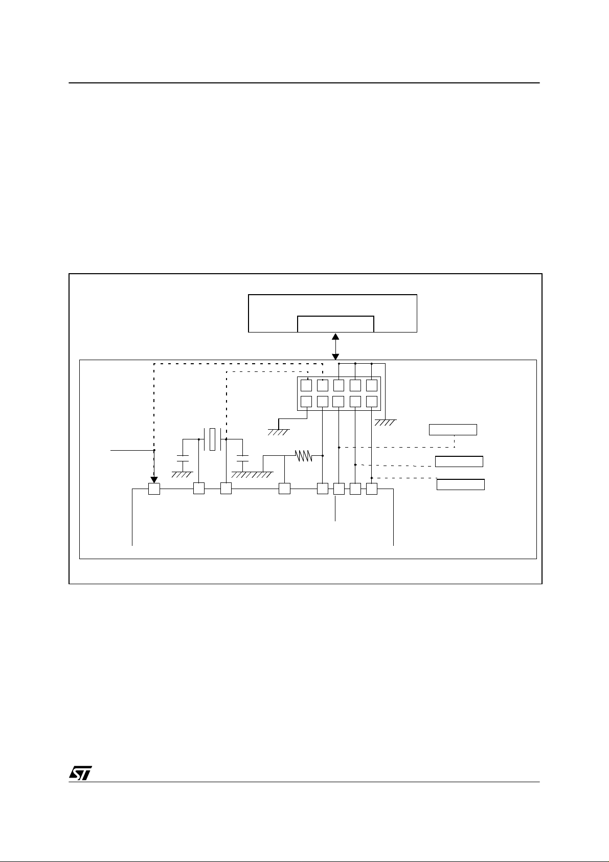
Figure 1. ICP Hardware Design
PROGRAMMING TOOL
ICC CONNECTOR
APPLICATION
POWER SUPPLY
OPTI ONAL
(See tex t)
C
L2
DD
V
OSC2
OPTIONAL
(See tex t)
C
L1
OSC1
ST7
975 3
10kΩ
SS
V
ICCSEL/VPP
ICC Cabl e
RESET
ICCCLK
1
246810
ICCDATA
APPLICATION BOARD
ICC CONNECTOR
APPLICATION
RESET SOURCE
Isolation
Isolation
Isolation
APPLICATION
I/O
3/11
Page 4

ON-BOARD PROGRAMMING METHODS FOR XFLASH AND HDFLASH ST7 MCUs
2 APPLICATION RUNNING DURING P ROGRAMMING
This method is primarily for applications that cannot be stopped and which have to keep some
kind of software kernel running all the time (generally for security or safety reasons).
It also covers, and this is the most common reason for not using ICP, applications where the
application designer ch ooses alternat ive means of implementing th e programm ing process,
specifically:
– The hardware connection to the programming tool, where the new firmware is stored
– The software protocol that defines the commands, status and data format.
A typica l case is w hen a com mu nicatio n port alre ady us ed in th e appli cation i s availa ble: It
avoids implementing an additional connector just for the ICP process: this approach is widely
used for devices with a CAN or USB interface.
Using your own protocol for on-board programming has the advantage of allowing flexibility in
terms of hardware implementation. However, some firmware must already be present on the
MCU in orde r to run the com munica tion pr otocol: T his metho d can thus be used on ly fo r reprogra mming , wh ich imp lies th e MC U has been progra mm ed at le ast onc e be fore wi th another method. Another constraint is that it is not possible to reprogram the whole program
memory of the MCU: nor can the reprogramming firmware itself be altered.
ST7 STMicroel ectron ics MCUs wit h HDFLAS H and XFLAS H have thi s capability of running
user-specific firmware to perform In-Application Programming (IAP) of the MCU program
memory.
This feature not only allows the application to keep some background tasks running, but also
to allows you to use any type of communication protocol for the reprogramming process.
2.1 IAP OVERVIEW
The ST7 progra m mem ory i s divid ed into several (up to 3) s ectors. O nly S ector 0 c annot be
programmed or eras ed in n orm al (user m ode) op eration. So this sector can be used to execute the firmware handling the reprogramming process, without being altered.
Reprogramming any of the other sec tors is possible, and is based on the execution of a specific software sequence, for which a software library, the IAP driver, is provided by STMicroelectronics.
The Sector 0 firmware handles the complete protocol and sequencing of the operations, and
some tasks that cannot be stopped during the programming process.
In contrast to th e ICP proc ess, the e mbedde d ha rdwa re perip herals can be activa ted by the
Sector 0 firmware to carry out some background tasks. The only limitation is that the Interrupt
Requests coming from these peripherals (Reception on UART, Timer overflow, ..) can be
processed only after the IAP driver has completed the requested operations. A notable excep-
4/11
Page 5

ON-BOARD PROGRAMMING METHODS FOR XFLASH AND HDFLASH ST7 MCUs
tion is the hardware watchdog that remains active: It must therefore be refreshed before performing any Program/Erase operations on the FLASH.
2.2 IAP PRACTICAL IMPLEMENTATION
2.2.1 General architecture
As already stated, a fi rmware must already hav e been l oaded i nto Sector 0. This fi rmware has
three purposes:
– Performing the Erase/Write operations on Sector 1 or 2 of program memory.
– Receiving the new data to be programmed.
– Managing the whole process protocol (Commands and status).
Therefore the fir mware con tained in th e S ec tor 0 is gener ally bas ed on thr ee mo dules : Pro tocol layer, Data Transfer Layer and IAP Driver (Figure 2)
Figure 2. IAP Architecture
Software architecture
Commands
Data Flo w
Protocol Layer
New Data
Status
Data Transfer Layer
MCU RAM
IAP Driver
MCU FLASH
This chart only gives the generic sc hem e of an IAP application, however the various types of
New Data
sources,
Data Tran sfer
physic al supp or ts, and t he
Protocol Layer
interfac es c an
lead to a wide range of practical implementations.
5/11
Page 6

ON-BOARD PROGRAMMING METHODS FOR XFLASH AND HDFLASH ST7 MCUs
2.2.2 Implementation with no external in ter face
A particular implementation is the case where
support, and the
Protocol Layer
interfaces are wi thin the MCU itself. This is particu larly suit-
New Data
source, the
Data Transfer
physica l
able for calibration operations when the MCU needs to autonomously set or update s ome data
in its program memory.
In cases where only one-time progr amming ( during initialization for instance) is needed, I AP
can save using an embedded or external data EEPROM module.
2.2.3 Upgrade from serial EEPROM
This example corresponds to STMicroelectronics Application Note AN1576:
Programming drivers for ST7 HDFLASH OR XFLASH MCUs
In this AN1576, the
Data Transfer
module is based, as example, on a SPI or I²C driver.
.
In Application
Figure 3. Upgrade from serial EEPROM
ST7 MCU
SPI or I²C
New Data
in E²PROM
6/11
Commands Status
Manual switch
LED
Page 7

ON-BOARD PROGRAMMING METHODS FOR XFLASH AND HDFLASH ST7 MCUs
2.2.4 USB-based example
In this example, the USB link is used for the
Protocol Layer
interfaces and
Data Transfer
sup-
port.
This implementation is an ideal example of IAP because the fact that the USB link is already
available means that you get a connection to the pr ogramming tool for free. On top of that, the
USB protocol itself allows the same media support to be used for the New Data and the Command/Status transfer.
The final scheme is there slightly different from Figure 2 since the
Data Transfer
layer and the
Protocol layer interfaces are merged into a DFU driver.
Figure 4. Device Firmware Upgrade by USB
Protocol layer
Commands
Status
IAP driver DFU driver
USB
Status
Commands
New Data
ST7 M C U
MCU RAM
Host PC Computer
7/11
Page 8

ON-BOARD PROGRAMMING METHODS FOR XFLASH AND HDFLASH ST7 MCUs
2.2.5 Local Network example
A multi-MCU application is another case where the IA P appr oach is particularly suitable, with
two main architectural schemes: gateway or direct network connection.
2.2.5.1 Gateway MCU
The idea is to define one of the MCUs as the gateway to the programming tool, and to link (in
a local netw ork) all the other MCUs to th is comm on node . As a cons eque nce, onl y one external connector is needed to reprogram all the assembled MCUs (including the gateway), and
the gateway M CU c an prov ide ad ditional sec urity by prev enting ac cess t o t he programm ing
lines of the other MCUs.
Ideally, the internal links already exist in the application (the CAN network is a good example),
otherwise if they have to be implemented, multiplexed buses (hardware or software) such as
I²C are obviously preferable as used for connecting MCU 1 & MCU 2 in Figure 5
Figure 5. IAP through a local network and gateway MCU
MCU 1
Status
MCU 2
Commands
MCU 3
Gateway MCU
New Data
Application system
Programming tool
2.2.5.2 Connection to internal multiplexed bus
In this scheme there is no gateway MCU, and the programming tool is directly linked to the internal multiplexed bus of the system.
The advantage of this solution is to save some I/Os by removing the gateway MCU. It is a low
cost solution that should be consider ed if an internal multiplexed bus is available. However,
the draw back is that t he connec tion to th e p rogram m ing t ool a lso gives direct acc ess to the
whole internal system: the use of the gateway avoids this issue.
8/11
Page 9

ON-BOARD PROGRAMMING METHODS FOR XFLASH AND HDFLASH ST7 MCUs
Figure 6. IAP with direct connection to the local network
MCU 1
MCU 2
Status
Commands
MCU 3
Application system
New Data
Programming tool
9/11
Page 10

ON-BOARD PROGRAMMING METHODS FOR XFLASH AND HDFLASH ST7 MCUs
3 FEATURES SUMM AR Y
Both ICP or IAP methods have their own advantages and drawbacks. Choosing the right solution for each application can be done based on the elements given in the Table 1.
Table 1. ICP compared to IAP
Topic ICP IAP
Requires a programming operation before
ICP or IAP
Sector 0 upgrade Possible Not possible
Application kept running No Yes, from sector 0
Connection to program-
ming tool
Multiple MCU syste m
No need
ICC comp atibility Vendo r spe cific
Multiple ICC connection
Sector 0 and option bytes need to be programmed first
Gatew ay o r mu lt iple x ed bus
4 GETTING MORE INFORMATION
For more detailed information on ICP and IAP please refer to:
AN1576: In-Application Programming drivers for ST7 HDFLASH or XFLA SH MCUs
ST7 Flash Programming Reference Manual
ST7 ICC Reference Manual
10/11
Page 11

ON-BOARD PROGRAMMING METHODS FOR XFLASH AND HDFLASH ST7 MCUs
“THE PRESENT NOTE WHICH IS FOR GUIDANCE ONLY AIMS AT PROVIDING CUSTOMERS WITH
INFORMATION REGARDING THEIR PRODUCTS IN ORDER FOR THEM TO SAVE TIME. AS A RESULT, STMICROELECTRONICS SHALL NOT BE HELD LIABLE FOR ANY DIRECT, INDIRECT OR
CONSEQUENT IAL DAMAGES WI TH RESPECT TO ANY CLAIMS ARIS ING FROM THE CONTENT OF
SUCH A NOTE AND/OR THE USE MADE BY CUSTOMERS OF THE INFORMATION CONTAINED
HEREIN IN CONNECTION WITH THEIR PRODUCTS.”
Information furnished is believed to be accurate and reliable. However, STMicroelectronics assumes no responsibility for the consequences
of use of such information nor for any infringement of patents or other rights of third parties which may result from its use. No license is granted
by implic ation or otherwise under any patent or patent ri ghts of STM i croelectr oni cs. Spec i fications mentioned i n this publication are subje ct
to change without notice. This publication supersedes and replaces all information previously supplied. STMicroelectronics products are not
authorized for use as cri tical comp onents in life support dev i ces or systems wi thout the express written approv al of STMicroel ectronics.
The ST logo is a registered trademark of STMicroelectronics
2002 STMicroelectronics - All Rights Reserved.
STMicroelectronics Group of Compan i es
http://www.s t. com
Purchase of I
2
C Components by STMicroelectronics conveys a license under the Philips I2C Patent. Rights to use the se components in an
2
I
C system i s granted pro vi ded that the sy stem conforms to the I2C Standard Specification as defined by Philips.
Australi a - B razil - Canada - China - Finl and - France - Germany - Hong Kong - Ind ia - Israel - Italy - Japan
Malaysi a - M al ta - Morocco - Singapore - Spain - Sw eden - Switz erland - United Kingdom - U.S.A.
11/11
 Loading...