

Page 1

AN1572
Application note
Power-down time-stamp function in serial real-time clocks (RTCs)
By Doug Sams
Introduction
Power-down time stamp and the Halt bit
Many serial RTC devices from STMicroelectronics include a feature known as power-down
time stamp. One register bit, Halt (HT), controls this feature. It is important that users
understand three things about the HT bit in order to ensure correct operation of these
devices.
1. Upon power-up, prior to writing any of the clock/calendar registers - that is, prior to
writing any address in the range 00h to 07h - the user must first clear the HT bit by
writing it to 0 (in bit 6 of address 0Ch).
2. Writing to addresses 00h to 07h (upon power-up) without first clearing the HT bit will
result in the counters being overwritten, thus corrupting the time/date.
3. Before the HT bit is cleared, reads of the device will return the time of power-down (or,
in the case of the M41T82/83/93, the time of the last read or write prior to power-down).
May 2012 Doc ID 10604 Rev 2 1/9
www.st.com
Page 2
Address auto-increment and clock data coherency
When reading and writing the time/date, users should always use the address autoincrement feature of the serial interface. This ensures that the data is transferred coherently
between the user and the counters. The time/date values read from the counters will all
come from the same instant in time (or be written to the counters at the same instant in
time). This does not apply to the non clock registers (eg, Flags or Watchdog registers), only
to the clock/calendar registers at addresses 00h to 07h.
For example, without using auto-increment, the user must read the time using multiple
accesses. On the first access, the seconds are read. Then, on the next transfer, the
minutes are read. This continues until all the date and time values have been read as
shown in the timing diagram below.
AN1572
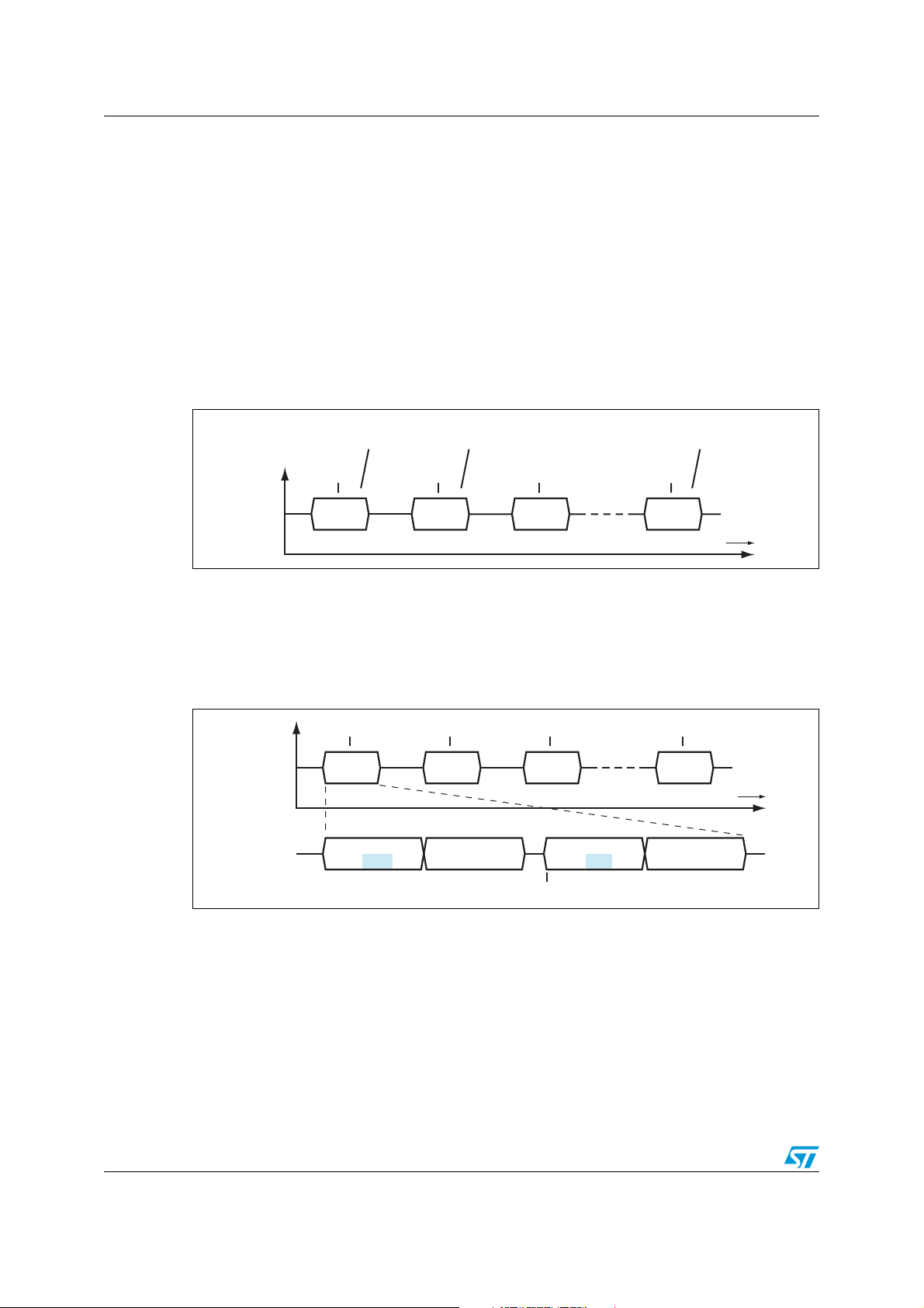
Figure 1. I
2
C timing sequence
1ST ACCESS 2ND ACCESS 7TH ACCESS
BUS
ACTIVITY
t
1
READ
SECONDS
t
2
READ
MINUTES
t
3
READ
HOURS
t
7
READ
YEAR
time
These transfers, in more detail, are depicted below. To read the seconds, two 2-byte
transfers occur in sequence. First, the processor sends the slave address and write bit
followed by the register address (01h). Then the slave address is sent again, with the read
bit, followed by a read of the seconds register. To read the minutes, this same sequence is
repeated, but with a different register address (02h).
Figure 2. Detailed I
BUS
ACTIVITY
2
C timing sequence
t
1
READ
SECONDS
t
2
READ
MINUTES
t
3
READ
HOURS
t
7
READ
YEAR
time
SEND SLAVE ADDR
AND WRITE BIT
1 BYTE 1 BYTE 1 BYTE 1 BYTE
SEND SECONDS
REGISTER ADDR
In reading the time this way, each byte comes from a different time. The seconds are from
time t
, the minutes are from time t2, and so forth. That is, the seconds, minutes, hours,
1
and so forth, are each read at a different instant in time. They are not coherent; they are not
from the same instant in time.
Example: the user begins reading at 23:59:59 (t
59 minutes (at t
00:00:00. So the hours are read (at time t
). Before the hours are read, the RTC increments such that the new time is
2
) as 00 and not 23. Thus the time, when re-
3
assembled, will appear to be 00:59:59. It is incorrect by one hour. Thus, it is better to read
all the time/date registers during the same transfer so that they come from the same instant
in time. That way, the time read will be coherent.
2/9 Doc ID 10604 Rev 2
SEND SLAVE ADDR
AND READ BIT
t
1
), and reads 59 as the seconds, then reads
1
READ SECONDS
REGISTER
Page 3
AN1572
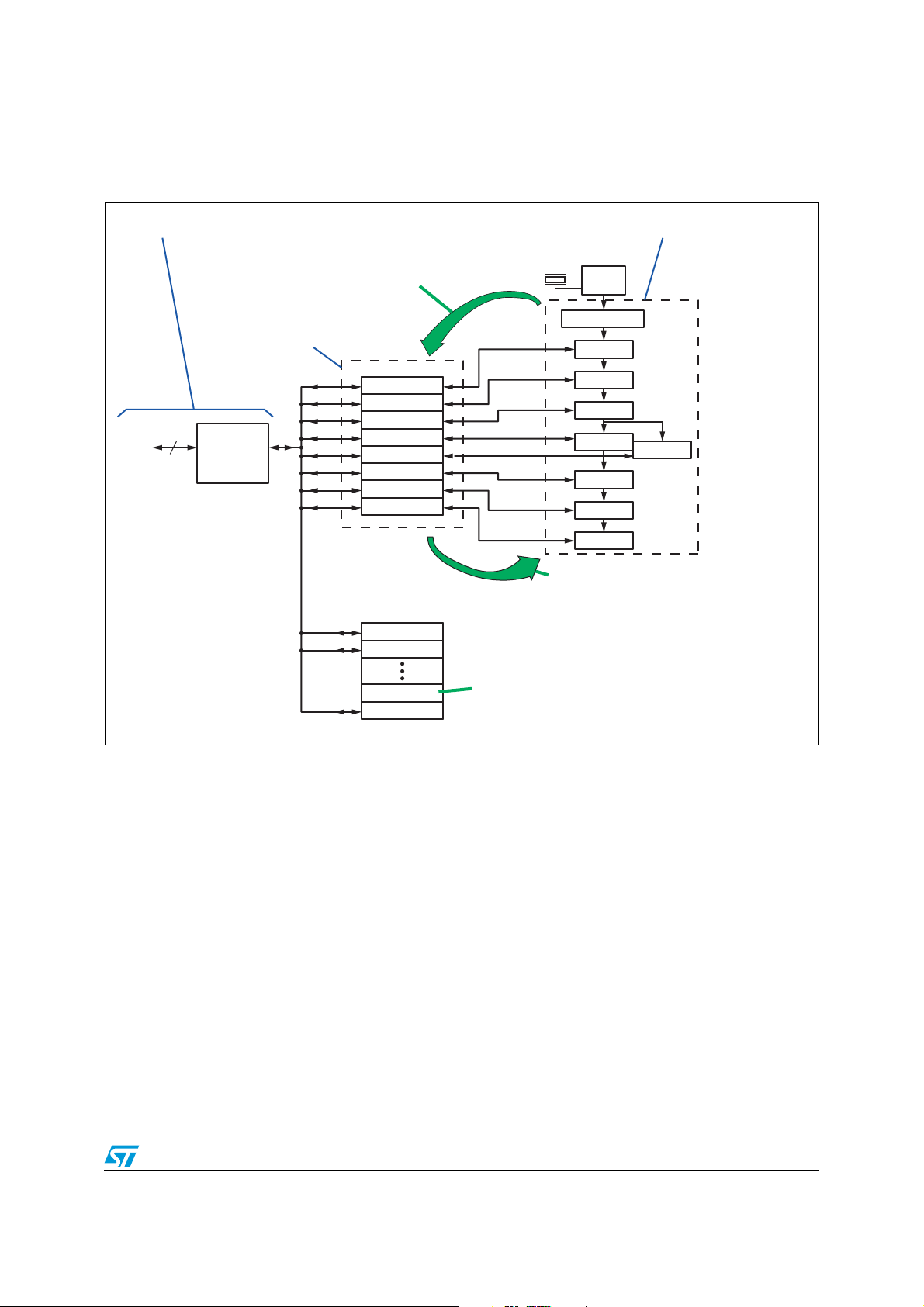
Buffer/transfer registers
Figure 3. Buffer/transfer registers
USER SIDE
I2C
2
AT START OF READ OR WRITE,
DATA IN COUNTERS IS COPIED TO
BUFFER/TRANSFER REGISTERS.
READ / WRITE
BUFFER-TRANSFER
REGISTERS
SECONDS
MINUTES
HOURS
I2C / SPI
INTERFACE
DAY-OF-WEEK
MONTHS
YEARS
CENTURIES
NON-CLOCK
REGISTERS
SQUAREWAVE
CALIBRATION
DATE
RTC COUNTERS
32KHz
OSC
DIVIDE BY 32768
1 Hz
COUNTER
COUNTER
COUNTER
COUNTER
COUNTER
COUNTER
COUNTER
AFTER A WRITE, DATA IS TRANSFERRED
FROM BUFFERS TO COUNTERS
COUNTER
ALARM / HALT
WATCHDOG
With a serial RTC, the user accesses the device via its serial interface, either I
HALT BIT SET AT POWER-DOWN
2
C or SPI.
Inside the RTC, the serial interface does not directly access the counters. Instead, a set of
buffer/transfer registers sit between the serial interface and the counters. Reads and writes
by the user will transfer data into and out of the buffer/transfer registers.
At the start of any I
2
C (or SPI) transfer, the device copies the counters into the
buffer/transfer register. Thus, when the user is reading the time/date, a fresh copy has been
placed in the registers. More importantly, because all the counters are simultaneously
copied into the registers, the time/date found in them is coherent - the seconds, minutes,
hours, etc, all come from the same instant in time.
The buffer/transfer registers ensure coherency and that none of the counter values are
incremented while the data is being transferred.
Doc ID 10604 Rev 2 3/9
Page 4

Address auto-increment
The address auto-increment feature of the serial interface allows the user to specify the first
register address to be transferred, then, after each data byte is transferred, it automatically
increments the address pointer to the next register. Thus, if the user attempts to read (or
write) more than one byte during a transfer, the register address pointer will automatically
point to the correct address for each successive byte transferred.
In the example below, the register address pointer is initialized to the seconds register
address (1). During the subsequent read, the seconds value is transferred first, then the
address pointer is incremented and the minutes are transferred next, and so forth, until all of
the time/date registers have been transferred. This is done as one continuous serial bus
transfer.
AN1572
Writes
Figure 4. I
SEND SLAVE
ADDR AND
WRITE BIT
2
C address auto-increment feature
SEND SECS
REGISTER
ADDRESS =1
SEND SLAVE
ADDR AND
READ BIT
t
1
READ
SECONDS
REG ADDR 1 2 76543
READ
MINUTES
READ
HOURS
READ
DAY OF
WEEK
READ
DAY OF
MONTH
READ
MONTH
READ
YEAR
Using this feature, all the bytes in the buffer transfer registers are copied from the counters
at time t
, and then shifted out as a coherent date/time value.
1
Thus, the combination of buffer/transfer registers and address auto-increment enable
reading and writing of the time/date to occur coherently no matter where in time the transfer
occurs. Even if the counters increment during the transfer, the value shifted in or out is from
the buffer/transfer registers and is not affected by the counters incrementing.
At the start of every transfer, read or write, the counters are copied to the buffer/transfer
registers (that is, if the Halt bit is 0). Thus, when write data begins shifting into the
buffer/transfer registers, it is overwriting a fresh copy of the time/date. At the end of the
write cycle, all the buffer/transfer registers are copied back into the counters. If only one
byte of the time/date is changed, then the corresponding counter is loaded with the new
value while all the other counters are loaded with the same values they had milliseconds
earlier at the start of the serial transfer.
That is, while only one byte was written by the user, all the counters were updated from the
buffer/transfer registers. One counter received the newly written value while the other
counters received the same values which had been copied from them milliseconds earlier at
the start of the transfer. In short, the counter values were copied to the buffer/transfer
registers, modified, and then copied back into the counters.
4/9 Doc ID 10604 Rev 2
Page 5

AN1572
Halt bit
Whenever the Halt bit (HT, bit 6 of address 0Ch) is a 1, the device halts the automatic
copying of the counters to the buffer/transfer registers at the start of a read or write access.
Thus, if the user writes the HT bit to 1, the buffer transfer registers will be frozen with the
time/date that the HT was written. Subsequent reads of the date/time will continue returning
the same value. Hence, with HT=1, at the start of a read/write sequence, the counters are
not copied into the buffer/transfer registers. They remain frozen with the time at which HT
was written to 1.
The HT bit is set to 1 automatically at power-down, when V
backup mode (except as noted below in M41T82 / 83 / 93).
Power-down time stamp
For most RTCs with battery switchover, the time/date counters are copied into the
buffer/transfer registers at power-down. Thus, the time of power-down is frozen in the
buffer/transfer registers. In applications where the duration of power outages needs to be
known once power returns, the application can read the time of power-down and compare
that to the current time to determine how long the device was in backup mode.
M41T82 / 83 / 93
The M41T82/83/93 RTCs do not save the time/date at power-down. Thus, when VCC fails
and their HT bits are set, the buffer/transfer registers will contain the time of the last access
prior to power-down rather than the actual time of power-down.
Applications needing to know the duration of an outage can work around this by
implementing periodic reads of the RTC. For example, if the software is configured to read
the RTC once per minute, upon power-down, the buffer/transfer registers will contain a
time/date value within one minute of the actual time of power-down. Applications requiring
more resolution can read the RTC more frequently.
fails and the RTC switches to
CC
Writes with the HT bit set
Whenever a write occurs to any of the RTC date/time register addresses (00h to 07h), all
eight registers are copied back into the RTC counters. Regardless of whether one byte is
written or several, all eight bytes are copied back into the counters. This only applies to the
date/time addresses 00h to 07h.
If the HT bit is set, then the buffer/transfer registers contain the time of power-down (or the
time of the last access for the M41T82/83/93). If a write occurs to any of these eight
addresses, then the time of power-down (or last access) will be copied back into the
counters. This has the effect of making the RTC appear to have stopped running at powerdown.
Users should always clear the HT bit prior to writing any of the date/time registers (00h to
07h) to prevent corruption of this nature.
Doc ID 10604 Rev 2 5/9
Page 6

Stop bit (ST)
If the oscillator has been determined to have stopped, it is recommended that users set and
then clear the oscillator stop bit (ST, bit 7 of address 1). This causes additional current to be
briefly injected into the oscillator to help get it running. We recommend using this kick-start
feature only when the oscillator is not running such as when the OF bit (oscillator fail status
bit) is set or when the device is being powered up for the first time.
If, upon power-up from backup mode, it is determined the device needs kick-starting, the
user should first clear the HT bit before setting the ST bit. Because the ST bit is part of the
seconds register, a write of the ST bit will result in the buffer/transfer registers being copied
to the counters. And if the HT bit is still set from power-down, the buffer/transfer registers
will contain the time of power-down. Thus kick-starting the device with HT set will result in
overwriting the date/time counters.
Furthermore, the user is reminded that the ST bit, being part of the seconds register, must
be packed with the seconds value. That is, the user must implement a read-modify-write
sequence on the seconds register when toggling the ST bit.
AN1572
6/9 Doc ID 10604 Rev 2
Page 7

AN1572
Recommended power-up sequence
The following flowchart shows one way of accessing the RTC after power-up which avoids
any issues with the HT bit.
Figure 5. Recommended power-up sequence
Power-up from backup
Optional: Read time/date
(time of power-down).
Optional: Read time/date
off_duration = present_time –
time_of-power-down
Clear HT bit
(present time).
Clear any flags (read flags register,
where applicable)
Optional: Re-initialize watchdog
(where applicable)
Optional: Re-enable / Re-initialize
timer (where applicable)
END
Doc ID 10604 Rev 2 7/9
Page 8

Revision history
Table 1. Document revision history
Date Revision Changes
Jun-2004 1 Initial release.
02-May-2012 2 Document completely rewritten; updated title.
AN1572
8/9 Doc ID 10604 Rev 2
Page 9

AN1572
Please Read Carefully:
Information in this document is provided solely in connection with ST products. STMicroelectronics NV and its subsidiaries (“ST”) reserve the
right to make changes, corrections, modifications or improvements, to this document, and the products and services described herein at any
time, without notice.
All ST products are sold pursuant to ST’s terms and conditions of sale.
Purchasers are solely responsible for the choice, selection and use of the ST products and services described herein, and ST assumes no
liability whatsoever relating to the choice, selection or use of the ST products and services described herein.
No license, express or implied, by estoppel or otherwise, to any intellectual property rights is granted under this document. If any part of this
document refers to any third party products or services it shall not be deemed a license grant by ST for the use of such third party products
or services, or any intellectual property contained therein or considered as a warranty covering the use in any manner whatsoever of such
third party products or services or any intellectual property contained therein.
UNLESS OTHERWISE SET FORTH IN ST’S TERMS AND CONDITIONS OF SALE ST DISCLAIMS ANY EXPRESS OR IMPLIED
WARRANTY WITH RESPECT TO THE USE AND/OR SALE OF ST PRODUCTS INCLUDING WITHOUT LIMITATION IMPLIED
WARRANTIES OF MERCHANTABILITY, FITNESS FOR A PARTICULAR PURPOSE (AND THEIR EQUIVALENTS UNDER THE LAWS
OF ANY JURISDICTION), OR INFRINGEMENT OF ANY PATENT, COPYRIGHT OR OTHER INTELLECTUAL PROPERTY RIGHT.
UNLESS EXPRESSLY APPROVED IN WRITING BY TWO AUTHORIZED ST REPRESENTATIVES, ST PRODUCTS ARE NOT
RECOMMENDED, AUTHORIZED OR WARRANTED FOR USE IN MILITARY, AIR CRAFT, SPACE, LIFE SAVING, OR LIFE SUSTAINING
APPLICATIONS, NOR IN PRODUCTS OR SYSTEMS WHERE FAILURE OR MALFUNCTION MAY RESULT IN PERSONAL INJURY,
DEATH, OR SEVERE PROPERTY OR ENVIRONMENTAL DAMAGE. ST PRODUCTS WHICH ARE NOT SPECIFIED AS "AUTOMOTIVE
GRADE" MAY ONLY BE USED IN AUTOMOTIVE APPLICATIONS AT USER’S OWN RISK.
Resale of ST products with provisions different from the statements and/or technical features set forth in this document shall immediately void
any warranty granted by ST for the ST product or service described herein and shall not create or extend in any manner whatsoever, any
liability of ST.
ST and the ST logo are trademarks or registered trademarks of ST in various countries.
Information in this document supersedes and replaces all information previously supplied.
The ST logo is a registered trademark of STMicroelectronics. All other names are the property of their respective owners.
© 2012 STMicroelectronics - All rights reserved
STMicroelectronics group of companies
Australia - Belgium - Brazil - Canada - China - Czech Republic - Finland - France - Germany - Hong Kong - India - Israel - Italy - Japan -
Malaysia - Malta - Morocco - Philippines - Singapore - Spain - Sweden - Switzerland - United Kingdom - United States of America
www.st.com
Doc ID 10604 Rev 2 9/9
 Loading...