

Page 1
1.E-06
0.02
REF
TS971 based Elec tret Condens e r Microphone am plifie r
This application note explains how to implem ent
the TS971 as a microphone pre-amplifier for an
Electret Condenser Microphone (ECM). This type
of microphone has one of the bes t price to performance ratio on the market.
Microphone pre-amplifiers are very common in to-
day’s appliances, digital appliances have adopted
and kept the typologies used in analog ones. This
block is helping to interface the microphone to the
A/D converter by buffering, filtering and amplifying
the microphone signal.
1 - DEVICE PRESENTATION
AN1534
APPLICATION NOTE
by R.CITTADINI & F.POULIN
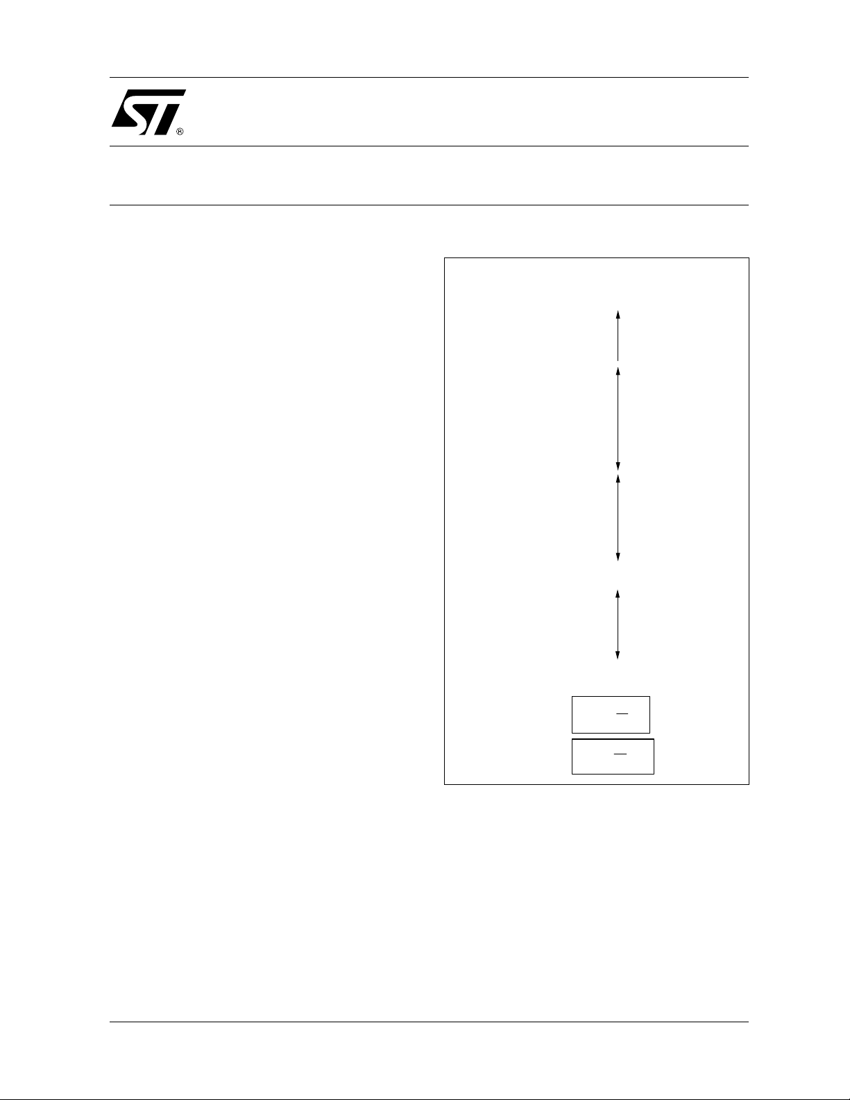
Table 1: Acoustic Units Reference Table
Acoustic
Intensity
I in W/m
1.E+02 200 140
1.E+00 20 120
1.E-02 2 100
1.E-04 0.2 80
Acoustic
Pressure
2
p in Pa SPL in dB
Sound
Pressure
Activity
Level
Ear Damage
130
110
Night Club, Factory Floor
90
Many low noise amplifiers exist in the market. Oldies (but still goodies!) are mainly dual ones like
LM833, MC33078. But few are able to reach low
voltages and are not avai lable in today’s sm allest
packages.
The TS97x is a fami ly including single, dual and
quad low-noise operational amplifier. It features
excellent audio characteristics: low distortion
(0.003% THD @ F=1kHz) and a 4nV/sqrt(Hz)
equivalent input noise v oltage with a 1/ f corner @
100Hz. Thanks to those characteristics, it helps
keeping an optimal Signal to Noise ratio, a critical
point at the entry of the audio amplification chain!
These devices al so allows a higher fidelity thanks
to a 4V/µs Slew Rate and 12 MHz Gain Bandwidth
Product. This enab les the amplifier to cope with
quick variations of the input signal well over the
audio bandwidth.
The family i s available in com pact packages like
SOT23-5 for TS971 or even the thin and rather
compact package like TSSOP for TS972/4. This
allows them to be used in portab le and miniature
digital appliances like PDA or Cellular Phones and
also in thin notebook computers.
70
Conversation
60
50
1.E-08 0.002 40
30
10
×=
(Log10SPL
I
(Log20SPL
×
=
p
Recording Studio
I
)dB()
REF
p
)dB()
REF
1.E-10 0.0002 20
I
= 1.E-12 p
REF
= 0.00002 0 Minimum Level of Audition, Reference Level
2 - MICROPHONE CONSIDERATIONS
Preliminary knowledge of Acoustic Intensity (in
Watt/m
2
), Acoustic Pressure (in Pascal or Pa) and
Sound Pressure Lev el or SPL (in Decibels or dB )
is important. You can report to table 1 for more in-
formation.
ECM microphones follow m ore or less the same
characteristics, however Gain and surrounding
components may vary from one model to another.
June 2002
1/4
Page 2

AN1534 - APPLICATION NOTE
We selected a popular model from Panasonic: the
WM-60A series. It’s an omni-directional microphone with the following main characteristics:
❑ Operating: from 2 to 10V.
❑ Sensitivity: -44dB +/- 5dB (0dB=1V/Pa).
❑ Impedance: less than 2.2kΩ
❑ S/N ratio: more than 58dB
❑ Current Consumption: 0.5mA max
❑ Recommended Load Resistor: R
The sensitivity of the microph one defines its gain
as per the following formula:
ySensitivit
(
=
mike
So with a -44dB s ensitivity, we can conclu de that
the gain of the microphone is 0.0063V/Pa or
6.3mV/Pa. With this value, we can get a good idea
of the output voltage of the microphone . It would
be around 12.6µV for a quiet room (2mPa or
40dB) and wou ld reach approximately 6.3m V for
the climax of a symphonic orchestra (1Pa or
110dB). This sound data is with a source at 1
meter from the microphone. This reference is
mandatory, the di stance b etwe en t he m icrophone
and the audio signal is illustrated by the Acoustic
Intensity (in Watt/m
2
).
Let’s take the example of a conversation. It’s
equivalent to roughly 20mPa or 60dB SPL at 1
meter. So an Acoustic Intensity of 1µW and 126µV
at the output of the microphone. The intensity decreases with the squared value of the distance between the source and the microphone. So for a
distance of 5cm, you would get a value of 400µW.
As per the Table 1 formulas, we can calculate the
"equivalent SPL value a t 1m": 86dB, then we get
the Acoustic Press ure: 0.4Pa which gives us the
output of the microphone:
0.4 x 0.0063 = 2.52mV (distance divided by 20
and output voltage increased by the same ratio).
We can sum marize these consi derations into the
following checklist:
)
20
: 2.2kΩ
L
)Pa/V(10G
❑ What type of signal do you want to amplify?
❑ How powerful?At what distance?
❑ What are the minimum and maximum of
each above parameters?
With these values, you will be able the cal culate
the microphone’s output voltage range and be
able to choose the right gain of the amplifier hereafter.
Also, if you want to implement a noise canceling
function, you can also choose another type of microphone called bi-directional microphone or
noise canceling microphone.
3 - COMPONENTS CALCULATION
Let’s look now on h ow to implemen t such an am plifier with TS971. You can refer to schem atic on
Figure 1 hereafter. We’ve chosen a non-inverter
typology to exploit to the b est the low noi se characteristics of the device . Indeed, with an inverter
configuration, the input resistor adds significant
noise to the application.
First, let’s look on the beha vior in DC mode. T he
first goal is to polarize the El ectret Cond ens er M icrophone. By using R
and R2, we can polarize it
1
around Vcc/2 as per below formula:.
I
≈
mikepol
−
Vcc
+×
)A(
)RR(2
21
The only criteria is t hat this current must remain
below 0.5mA over the supply range (otherwise,
you can increase R1 value).
R
is also acting together with C1 as a filter for the
1
power supply line of the microphone. Then in AC
mode, C
allowing only R
is fixing the gain of the microphone by
1
to act (and not R2+R1 as C1 is
2
equivalent to a short circuit to the ground). And R
must equal RL=2.2kΩ for the microphone we’ve
chosen. In AC mode, this type of microphone can
be simplified and comp ared to a current sou rce in
parallel with R
, hence a voltage source.
2
Then to avoid ext ra of fset drift due to bias c urrent
mismatching, following resistor values need to
comply w it h the f o llow ing rule:
×
RR
++≈
RRR
348
65
+
RR
65
)Ohms(
The second step is, still in DC mode, to polarize
the reference pin of the TS971. It’s the inverting
pin here that will be set at Vcc/2 by the R5 and R6
bridge. C4 adds here additionnal filtering of this
reference voltage. This configuration allows the biasing or the "centring" o f the signal at mid-supply
voltage. Hence it allows to maximize the swing
within the supply voltage range. This bias voltage
just needs to be kept within V
means V
or Common Mode Input Voltage must
ICM
range. This
ICM
be at least 1.15V inside the s upply voltage rails,
i.e. from Vdd+1.15 to Vcc-1.15V.
2
2/4
Page 3
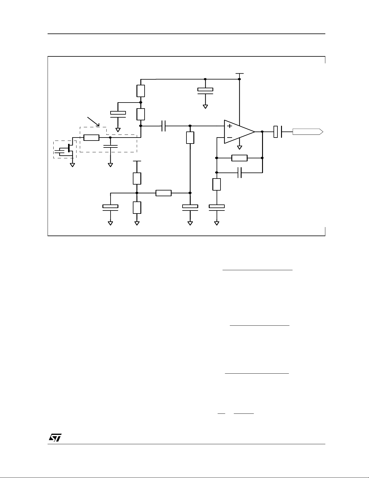
Figure 1: ECM Microphone Pre-amp. with TS971
e
R1
1k
C2*
10u
AN1534 - APPLICAT ION NOTE
Vcc = 2.7V min.
+
Optionnal
EMI filter
R
EMI
100R
C1
10u
+
C
EMI
47p
R2
2.2k
C5
100n
Vcc
Electret
Condenser
Microphone
+
C3
4.7u
R5
100k
R6
100k
R3
15k
C4
2.2u
This bridge can also be supplied by an ASIC’s
"Vref out" pin or by another operator of the op-amp
connected as a buffer (using the TS972, a dual
op-amp, this can be implemented easily).
An important note on the im ped anc e of the a mpl ifier is that, in AC mode, R
is equivalent to the in-
4
put impedance of the ampli fier stage. It must not
be too small to avoid the collapsing of the microphone signal!
The coupling capacitor (C
) makes this application
6
universal, however, you could omit it when attacking an A/D converter. In this case, you onl y have
to adapt the bridge set by R
& R6 to match the in-
5
put voltage range of the converter. Thanks to its
Rail-to-Rail output, the TS971 simplifies the process.
We’re coming now to the filter definition, when
looking at figure 1, we can see three filters: two
high pass and a low pass. Each has a 6dB/octave
attenuation factor.
The high pass filter is built by C
The theoretical formula to calculate F
, R4 and also R2.
5
or the
CL
TS461/971
R4
18k
R8
82k
C8*
R7
820R
+
+
180p
* Optional : refer to text
C7
3.3u
C6*
+
1u
Output
Lower Cutoff Frequency (here approximately 79
Hertz) is the following
≈
F
1CL
Another high pass filter is made by C
1
()
×+×π×
CRR2
542
and R7. The
7
cutoff frequency is better set at a lower value than
F
to have a stronger reduction (i.e. -12dB/oc-
CL
tave) of low frequencies (here 59Hz).
F
≈
2CL
1
××π×
CR2
77
Then for the low pas s f ilter (op tional), to c al culate
F
or the Higher Cutoff Frequency (here approx-
CH
imately 10.7kHz), we have the following formula::
CH
=
F
1
××π×
CR2
88
The next step is to configure G or the gain of the
amplifier (here 90 or +39dB):
R
8
1(G
R
7
R
4
×+≈
()
×
RR
+
24
microphon
theofGain)
)Hz(
)Hz(
)Hz(
3/4
Page 4

AN1534 - APPLICATION NOTE
This represents the gain of the amplifier in the
"non-filtered" bandwidth area. R
and R4 have to
2
be taken into consideration as they establish a
voltage divider. Changing R
value helps to modi-
7
fy the gain without being forced to change the values of the other comp onents (apart from the high
pass filter with C
).
7
What we refer to as the "gain of t he microphone" is
the gain we talk about in the "Microphone considerations" chapter. You need to consider the signal
fed to the microphone to avoid saturation or insufficient gain.
To be completely exhaustive, if you use C
, you
6
have to consider that it creat es together with the
impedance of the loa d Z
a high pass filter with
L
cutoff frequency def ined like abo ve (replacing R
with ZL and C5 with C6.
4- SPECIAL NOTE ON EMI
As you can notice on Figure 1, we have suggested
an optional Electro Magnetic Interference filter
(cutting frequencies above 33.8M Hz). With cellular phones being a constant company t o our daily
life, high power RF interferences need to be properly managed int o sens itive a mpl ification dev ices.
This filter has to be implemented close enough to
the microphone and we also have to pay attention
on not having too long connecting wires (antennas!). Ideally this application should be wired on a
double sided PCB with one side acting as ground
plane.
5 - COMPONENTS CALCULATION
So, in this example, we have a gain value of 90 or
+39dB and we have globally a band pass filter
with F
~60-80Hz and FCH =10.7kHz. Concerning
CL
the overall gain, we also have also to consider the
stage after the pre-amplifier. If it’s a CODEC or A/
D converter, it will most probably have its own amplification (usually +20d B gain). All together, this
gives the below chain for the chapter 1 example:
Stage \ V
4
Microphone Output 0.13mV
OUT
at 1 meter at 5 cm
(126µV)
TS971 Output
(+39dB)
Codec Output
0.11mV
(1 1.34mV)
0.11V 2.27V
(+20dB)
This configuration is well adapted to battery powered equipment as the overall maximum consumption of th is application is 3.3mA (0.5mA for
the microphone and 2.8mA max for TS971).
2.5mV
0.23V
Information furnished is bel ieved to be accurate and reliable. However, STMicroe lectronics assumes no responsibility for the
consequences of use of such information nor for any infringement of patents or other rights of third parties which may result from
its use. No li cense is granted by implication or otherwise unde r any patent or patent rights of STMicroelectronics. Specifications
mentioned in this publication ar e subject to change without notice. This publication supersedes and replaces all information
previously supplied. S TMicroelectronics products are not authorized for use as critica l components in life suppo rt devices or
systems without express written approval of STMicroelectronics.
Australi a - Brazil - Canada - Chin a - F i nl and - France - Germany - Hong Kong - Ind i a - Is rael - Ital y - J apan - Malaysia
Malta - Mor occo - Singapore - Spain - Sweden - Swi t zerland - U ni ted Kingdom - United Sta tes
4/4
© The ST logo is a registered trademark of STMicroelectronics
© 2002 STM icroelectronics - Pr inted in Ital y - All Rights Reserved
STMicr o el ectronics GROUP OF COMPANIES
© http://www.st.com
 Loading...