

Page 1

AN1530
APPLICATION NOTE
ACCURATE TIMEBASE FOR LOW-COST
ST7 APPLICATIONS WITH INTERNAL RC OSCILLATOR
by Microcontroller Division Applications
INTRODUCTION
The ST7 microcontroller con tains an internal RC oscillator, which may vary due to internal
component variation depending upon the surrounding conditions. This can lead to the wrong
calculation of the timing for the different peripherals like Timers, SCI etc. Timing calculation for
the peripheral can be done based on the internal RC frequency given in the datasheet, but due
to the variations in internal RC frequency from component to component, this leads to wrong
timing results in the application.
The purpose of this application note is to present a software solution for accurate timing by calibrating the inter na l perip heral pa ram eters ag ain st the v ariation of th e i nterna l RC osc illator.
This note focuses on ST7 MCUs with a non-calibrated RC. A 50 H z, 5 V source is applied as
a reference frequency to find the real internal RC oscillator frequency. The deviation of the internal frequency w ith respect to the data sheet frequ ency is applied to c orrect the peripher al
parameter values to obtain timing accuracy. This solution provides an innovative way to compensate the internal RC oscillator variation and to develop low cost applications.
Software is developed with using the ST7 software library (available free on the ST web site).
Software shows , h ow t o cal ibrate P WM signal o f TIME R A to produ ce a 5 K Hz fr equen cy. It
also gives an idea of how to calibrate the baud rate of the SCI (here it is calibrated for 9600
baud). An externally calibrated source (ex. Function generator) is used to apply 50 Hz and 5 V
as a reference.
AN1530/0702 1/12
1
Page 2
ACCURATE TIMEBASE FOR LOW-COST ST7 APPLICATIONS WITH INTERNAL RC...
1 SOFTWARE SOL UTION
1.1 MEASUREMENT PRINCIPLE
To measure the frequency of the internal RC, software uses the input capture pin of 16-bit
TIMER A. A calibrated sour ce is applied with 50Hz on the capture pin. Every falling ed ge on
this pin generates an interrupt (at 20ms time duration).
Softwar e has take n the int erna l RC fre que nc y o f t ypi cally 4 M Hz a s p er t he d atash eet . The
TIMER clo ck is selec ted as fc pu/2 (1 MH z). Co unter over flow is gen erated after 65.532 ms
(0xFFFF). This internal RC frequency should be chosen between the datasheet. max. and
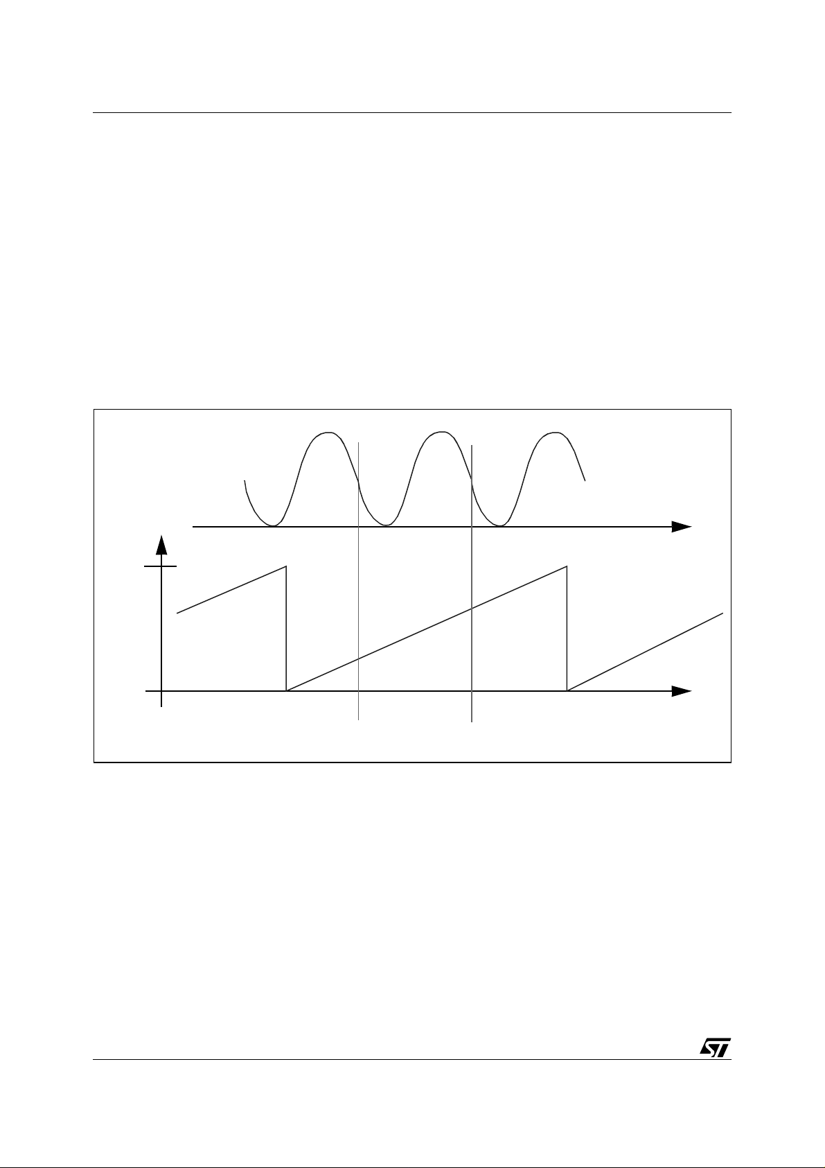
min. RC frequency values. Capture1 and Capture2 are stored as shown in Figure 1.
Figure 1. Timer Input Capture to measure the Reference frequency.
Calibrated source for
5 Vpp, 50 Hz
FFFFh
Free running
counter of TIMER A
0000h
Here two possibilities can occur during the calculation of the capture elapsed time. If Capture1
and Capture2 are on the single counter (as shown in Figure 1), time is calculated simply by
Capture Counter = Capture2 - Capture1
Second possibility is that counter overflow generates between the measurement of the
Capture1 and Capture2. This leads to a more complex calculation given by
Capture Counter= ((0xffff - capture1) + capture2)
This Measured Capture Counter is compared with the Ideal Capture Counter. Ideal Capture
Counter is calculated manually and here for the fcpu = 2 MHz, it gives 0x4E20. With this information Internal RC deviation is found.
Capture1 Capture2
2/12
2
Page 3

ACCURATE TIMEBASE FOR LOW-COST ST7 APPLICATIONS WITH INTERNAL RC...
InternalRCDeviationFraction
MeasuredCaptureCounter
-------------------------------------------------------------------------------=
CalculatedCaptureCounter
This fraction can be used to calibrate the other peripheral parameters to add precision to the
the timing calculations.
If a Mains Supply is used as an external source, this solution works for an European Supply
(50 Hz)). If a US supply (60 Hz) is used, the calculated Capture Counter will be 0x411B to find
the fraction for internal RC deviation.
A software routine is developed to find this fraction and utilize it to calibrate the peripheral parameters. this routine is included in the application. The basic software takes less than 30ms
to find the fraction, which gives the deviation of r eal RC frequenc y with referen ce to the datasheet frequency. This application incl udes a glitch filter algorithm and also takes the average
of 8 samples for finding the fraction. The basic algorithm and the average + glitch algorithms
are descr ibed in th e next c hap ters. T he sof tware t ak es l ess than 325 ms wi th t he av era ging
and glitch algorithms.
This routine ex ecut ion t ime inc ludes the 8 ca pture e lapse d tim es , w aiting t im es fo r th e cap tures and the loop calculations i nside the routine. T he routine execution time is affected mostly
by the capture waiting times. This routine will run in the background of the main application, so
MCU can run other tasks during thi s 30ms (bas ic software algorithm) or 325ms (for average
and glitch algorithm) period.
3/12
Page 4
ACCURATE TIMEBASE FOR LOW-COST ST7 APPLICATIONS WITH INTERNAL RC...
1.2 BASIC ALGORITHM
This algorithm measures the deviation of internal RC oscillator frequency in terms of Fraction.
This will take 30ms to find the fraction. Software is developed in “C” language with the help of
the ST7 software library. It needs 9 bytes of RAM.
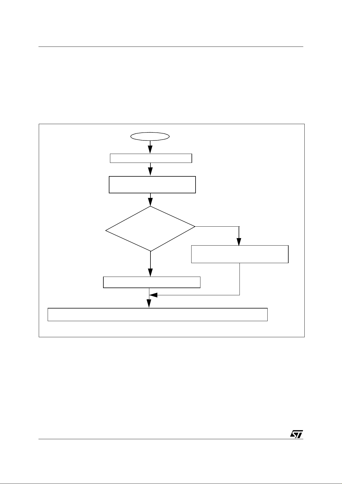
The software works as shown in the following flow chart for a single sample.
Figure 2. Basic Algorithm Flowchart
START
Initialisation of TIMER A capture
Measurement of the Capture1 and
Capture2 done
Is
counter overflow
generated
?
no
Capture Counter= Capture2 - Capture1
Internal RC deviation fraction = Measured Capture Counter / Calculated (Ideal) Capture Counter
Capture Counter= ( ( 0xffff - Capture1 ) +
Capture2 )
yes
4/12
Page 5

ACCURATE TIMEBASE FOR LOW-COST ST7 APPLICATIONS WITH INTERNAL RC...
1.3 AVERAGING AND GLITCH ALGORITHM
This algorith m a n a dded fe ature to se ction 1.2. When the 50 Hz sour ce h as no ise or spi kes,
this algorithm helps to prevent a wrong measurement of the reference signal. If you develop a
permanent hardware circuit to generate the 50 Hz signal, then it may contain noise signals as
well as glitches or spikes. This algorithm is a must in this case.
This software uses 12 bytes of RAM and takes 325 ms (one loop to find the average of 8 samples) to find the deviation fraction. The flowchart shows how this algorithm works.
Figure 3. Average and Glitch Algor ithm Flowchart
START
Initialisation of TIMER A capture and variables
Capture counter measurement
(Figure 2)
First sample of capture counter is stored (capture_range)
for glitch filtering
Check
no
Internal RC deviation fraction = Average Capture Counter / Calculated (Ideal) Capture Counter
sample = (+/-)10% of
capture_range
?
yes
Is
8 samples
over
?
yes
Average
no
5/12
Page 6

ACCURATE TIMEBASE FOR LOW-COST ST7 APPLICATIONS WITH INTERNAL RC...
1.4 CALIBRATION OF PERIPHERAL PARAMETERS
1.4.1 PWM Counter
Software calibrates the PWM of TIMER to produce the pulse train at 5 KHz frequency. Normal
PWM counter is given by the equation,
tfcpu
×
PWMCOUNTER
--------------------- -5–
=
PRESC
where, PWMCOUNTER = Counter value to load in OCiR register
t = Pulse period (in seconds)
fcpu = CPU clock frequency
PRE SC = Prescaler select ion
Variation in the internal RC affects the fcpu in above equati on. The measured fraction ( section
1.3) is applied to this term of the equation. This leads above equation to the new version,
PWMCOUNTER
t fcpu fraction
------------------------------------------------ 5–
=
××
PRESC
Calibration software calculates PWM counter value using the second equation. It takes care of
the internal RC variation and loads the correct value in the OCiR register to produce the desired frequency.
Here for the 5 KHz frequency generation, PWMCOUNTER will be 95 for fcpu = 2 MHz. When
you convert into Hex value from decimal, resolution will be of 1 count. So the accuracy is [(1/
95)*100] = 1.05%. The accuracy will be proportional to the variation in t and same as the
counter.
1.4.2 SCI Baud rate
SCI applica tions are the real t ime -critical ap plic ations . Th e t ransm it bau d rat e can be det ermined with the following equation,
Tx
---------------------------------------------------------------=
16PR×()
fcpu
TR×ETPR
×
where, Tx = Baud rate for transmission
6/12
fcpu = CPU clock frequency
PR = SCI generic prescaler
Page 7

ACCURATE TIMEBASE FOR LOW-COST ST7 APPLICATIONS WITH INTERNAL RC...
TR =Transmission rate divisor
ETPR = Extended Transmit Prescaler Division
The above equation is used normally without the ETPR selection. Due to the flexibility of
ETPR range (1 to 255), this software solution calibrates the SCI baud rate using the ETPR
register. Software keeps PR=1 and TR=1. Again the fraction is appli ed to the numerator of the
equation as the variation affects the fcpu only. The equation becomes,
×
fcpu fraction
---------------------------------------------------------------=
Tx
To calibrate the baud rate, software loads the value of 9600 in Tx. This gives the value in
terms of (PR * TR * ETPR). Software loads TR=PR=1, So the value is directly assigned to the
ETPR register. This value is loaded into the PR, T R and ETPR bits. For the 96 00 baud r ate,
this calibration gives ~9300 baud r ate ( where internal RC varies (-25%)). T his software is abl e
to communicate with the PC hyperterminal after using this calibration.
16
PR
×()
TR×ETPR
×
Here for the 9600 baud rate calculation, ETPR = 13, PR = TR = 1, for fcpu = 2 MHz. When you
convert into Hex value from decimal, resolution will be of 0.5 count. So the accuracy is [(0.5/
13)*100] = 3.84%. Accuracy will be proportional to variations in Baud rate and s ame as that of
the ETPR. For higher baud rate values, you have to go for a resolution 0.25 (logic can be extended as shown in software) to achieve better accuracy.
If SCI doesn’t have the ETPR prescaler then we can load PR=1 and assign the counted value
to TR directly.
2 CONCLUS ION
This software solution allows you to work with any time critical applications irrespective of the
variations of the internal RC oscillator frequency. Software is calibrated with reference to the
base of 4 MHz.
Software is developed using the ST7 software library functions. It takes less than 30ms for the
simple calibration version. With the averaging and glitch algori thms, it takes less than 325 ms.
Software includes correction for the PWM counter value and the SCI baud rate. The PWM
counter value gives the frequenc y with an accuracy of 1-2% a nd the SC I baud r ate gives an
accuracy of 3-4% after using this calibration software, when internal RC oscillator varies by (25%).
7/12
Page 8

ACCURATE TIMEBASE FOR LOW-COST ST7 APPLICATIONS WITH INTERNAL RC...
3 SOFTWARE EXAMPL E
This software example includes all the algorithms. It includes a basic algorithm for finding the
fraction and also contains average and glitch algorithms. It has calibration routines for the
PWM counter and SCI baud rate.
3.1 MAIN PROGRAM
/********************************************************************************
COPYRIGHT 2002 STMicroelectronics
Source File Name: main.c
Group : IPSW, CMG - IPDF
Author : MCD Application Team
Date First Issued: 01/07/2002
********************************Documentation**********************************
General Purpose - This routine provides internal RC deviation measurement and
calibration of PWM counter and SCI baud rate.
********************************Revision History********************************
Date: 01/07/2002 Release: 1.0
******************************************************************************/
#include "ST7lib_config.h" /*Configuration File*/
unsigned char cap;
unsigned int capture1,capture2;
const unsigned char buff1[36]= " SCI CALIBRATION DONE ";
/******************************************************************************
MAIN APPLICATION BEGINS
******************************************************************************/
#define TIMERB_PWM_CAL
#define SCI_CAL
void main (void)
{
/******************************************************************************
Variable declaration for measuring the capture inputs with averaging and
glitch filter algorithm
******************************************************************************/
unsigned char i;
unsigned int capture_range;
float fraction=0.0;
/******************************************************************************
Variable declaration for calibrating PWM w.r.t Internal RC frequency
******************************************************************************/
unsigned int PWM_CNT, PWM_CNT1;
/******************************************************************************
Variable declaration to calibrate SCI baudrate w.r.t Internal RC frequency
******************************************************************************/
unsigned char CALTR;
float CALTR_TEMP = 0.0;
/******************************************************************************
Initialisation of the varibles
******************************************************************************/
cap=capture1=capture2=0;
PWM_CNT = 0; PWM_CNT1 = 0; CALTR =0;
capture_range = 0;
8/12
Page 9

ACCURATE TIMEBASE FOR LOW-COST ST7 APPLICATIONS WITH INTERNAL RC...
/******************************************************************************
Enable MCC to watch the real internal RC oscillator frequency
******************************************************************************/
MCC_Init(MCC_DEFAULT);
MCC_Init(MCO_ENABLE);
/******************************************************************************
TIMER A Library called to capture the rising edge at the pin PF4
******************************************************************************/
TIMERA_Init(TIMER_FCPU_2); /*Timer clock is fcpu/2=1 MHz at fosc=4MHz*/
TIMERA_ICAP_Mode(TIMER_ICAP_1,T IMER_EDGE_0);
TIMERA_IT_Enable(TIMER_ICAP_IT_ ENABLE);
EnableInterrupts;
/******************************************************************************
Loop to capture 8 samples and to do averaging of it with using glitch
filter algorithm to protect the wrong signal capture
******************************************************************************/
for (i=0;i<8;i++) /*averaging done for 8 samples*/
{
while (cap != 2); /*wait loop for two captures*/
/*management the possibility of overflow of counter*/
if (capture2 < capture1)
{
capture2 = ((0xffff - capture1) + capture2);
}
else
{
capture2 = (capture2 - capture1);
}
capture2 = capture2 >> 3;
/**********************Glitch filtering Algorithm **********************/
if (i==0)
{
capture_range = capture2;
}
fraction = fraction + capture2;
if((capture2>(1.1*capture_range))||(capture2<(0.9 * capture_range)))
{
fraction =0; i=0;
}
capture1=capture2=cap=0;
}
/*fraction = Measured RC frequency/assumed internal RC Frequency (here 4 MHz)*/
fraction = ((float)fraction/0x4e20);
Nop;
/******************************************************************************
TIMER PARAMETER CALIBRATION
******************************************************************************/
#ifdef TIMERB_PWM_CAL
/********** Timer PWM generation for 5 KHz frequency*****************/
/******************************************************************************
100 value to get 100 microcesconds at 2MHz fcpu, equation is used as
per ST72F521 datasheet
******************************************************************************/
PWM_CNT = (int)(200 * fraction); /*numerator calculation*/
9/12
Page 10

ACCURATE TIMEBASE FOR LOW-COST ST7 APPLICATIONS WITH INTERNAL RC...
PWM_CNT = PWM_CNT >> 1; /*division by 2*/
PWM_CNT = PWM_CNT - 5;
PWM_CNT1 = (int)(400 * fraction); /*numerator calculation*/
PWM_CNT1 = PWM_CNT1 >> 1; /*division by 2*/
PWM_CNT1 = PWM_CNT1 - 5;
TIMERB_Init(TIMER_FCPU_2);
TIMERB_PWM_Mode(TIMER_OUTPUT1_R, TIMER_OUTPUT2_F, PWM_CNT, PWM_CNT1);
Nop;
#endif
/******************************************************************************
SCI TRANSMIT TIME CALIBRATION
******************************************************************************/
#ifdef SCI_CAL
#ifdef SCI_POLLING_TX
/******************************************************************************
SCI transmit time calibration for 9600 baudrate at fcpu=2MHz, this
communication is done with Hyperterminal of PC with the configuration:
baudrate=9600,Databits-8, stop bit-1,parity-None and Flowcontrol-None
******************************************************************************/
CALTR_TEMP = (float) (13 * fraction);
/***********Value 13 = PR*TR*ETPR, where PR=TR=1. ETPR = 13*******************/
CALTR = (char)(13 * fraction);
CALTR_TEMP = (float)(CALTR_TEMP - CALTR);
if (CALTR_TEMP > 0.5)
{
CALTR = CALTR + 1;
}
/***********SCI library called to send the message on Hyperterminal***********/
SCI_Init(SCI_DEFAULT_PARAM1, SCI_DEFAULT_PARAM2);
SCI_Extend_Baudrate(SCI_PR_1 + SCI_TR_1 + SCI_RR_1, CALTR, CALTR);
SCI_Mode(SCI_TX_ENABLE);
SCI_PutBuffer(buff1,sizeof (buff1));
SCI_PutByte(0x55);
while(!(SCI_IsTransmitCompleted()));
#endif
#endif
}
/******************************************************************************
END OF MAIN
******************************************************************************/
/******************************************************************************
Interrupt Subroutine for TIMER
******************************************************************************/
#ifdef _HIWARE_ /* test for HIWARE Compiler */
#pragma TRAP_PROC SAVE_REGS /* additional registers will be saved */
#else
#ifdef _COSMIC_ /* test for Cosmic Compiler */
@interrupt /* Cosmic interrupt handling */
#else#error"Unsupported Compiler!" /* Compiler Defines not found!*/
#endif
#endif
void TIMERA_IT_Routine ()
{
if (!cap)
{
10/12
Page 11

ACCURATE TIMEBASE FOR LOW-COST ST7 APPLICATIONS WITH INTERNAL RC...
while (TIMERA_Status_Flag(TIMER_FLAG_ICF1)!= TRUE);
cap++;
capture1 = TIMERA_ICAP_Getvalue(TIMER_ICAP_1);
TIMERA_Clear_Flag(TIMER_FLAG_ICF1);
}
else if (cap)
{
while (TIMERA_Status_Flag(TIMER_FLAG_ICF1)!= TRUE);
capture2 = TIMERA_ICAP_Getvalue(TIMER_ICAP_1);
TIMERA_Clear_Flag(TIMER_FLAG_ICF1);
cap++;
}
}
/**** (c) 2002 STMicroelectronics *************************** END OF FILE **/
11/12
Page 12

ACCURATE TIMEBASE FOR LOW-COST ST7 APPLICATIONS WITH INTERNAL RC...
“THE PRESENT NOTE WHICH IS FOR GUIDANCE ONLY AIMS AT PROVIDING CUSTOMERS WITH INFORMATION
REGARDING THE IR PRO DUCT S IN OR DER FO R THEM TO SAV E TIME . AS A RES ULT, STMIC ROEL ECTR ONI CS
SHALL NOT BE HELD LIABLE FOR ANY DIRECT, INDIRECT OR CONSEQUENTIAL DAMAGES WITH RESPECT TO
ANY CLAIMS ARISING FROM THE CONTENT OF SUCH A NOTE AND/OR THE USE MADE BY CUSTOMERS OF
THE INFORMATION CONTAINED HEREIN IN CONNECTION WITH THEIR PRODUCTS.”
Information furnished is believed to be accurate and reliable. However, STMicroelectronics assumes no responsibility for the consequences
of use of such information nor for any infringement of patents or other rights of third parties which may result from its use. No license is granted
by implic ation or otherwise under any patent or patent ri ghts of STM i croelectr oni cs. Specifications mentioned in thi s publicati on are subject
to change without notice. This publication supersedes and replaces all information previously supplied. STMicroelectronics products are not
authorized for use as cri tical comp onents in life support dev i ces or systems wi thout the express written approv al of STMicroel e ctronics.
The ST logo is a registered trademark of STMicroelectronics
2002 STMicroelectronics - All Rights Reserved.
STMicroelectronics Group of Compan i es
http://www.s t. com
Purchase of I
2
C Components by STMicroelectronics conveys a license under the Philips I2C Patent. Rights to use the se components in an
2
C system i s granted pro vid ed that the sy stem conforms to the I2C Standard Specification as defined by Philips.
I
Australi a - Brazil - Canada - China - Fi nl and - France - Germany - Hong Kong - India - Israel - I taly - Japan
Malaysi a - M al ta - Morocco - Singapore - Spain - Sw eden - Switz erland - United Kingdom - U.S.A.
12/12
 Loading...