

Page 1
AN1526
APPLICATION NOTE
ST7FLITE0 QUICK REFERENCE NOTE
by Microcontroller Division Applications
INTRODUCTION
The ST7FLITE0 extends the lower end of the ST7 range, designed to fit applications with
state-of-the-art features in a very small package.
ST7FLITE0 8-bi t MCUs have man y cost-sa ving features and they come w ith low-cost tool s,
providing a complete package to reduce both design and final appl ication costs to the absolute
minimum.
This application note highlights some small but very important aspects of the ST7FLITE0 that
users should not overlook when reading the datasheet.
Sections 2 and 3 contain helpful pointers and a table to help you star t working with ST7FLITE0
and its related tools.
Table 1. ST7Lite0 Features
Program memory
RAM
Data EEPROM
Package
Number of I/O pi ns
Vdd ra nge
Temperature range
IDDmax in RUN mode
LVD
Clock sources
A/D
Timers
Communication peripheral
Special features
1.5
Kbytes Flash (single voltage)
128 bytes
ST7FLITE05: no Data EEPROM
ST7FLITE09: 128 bytes Data EEPROM
SO16 (.150) or DIP16
13 (including 6 high current pins)
2.4V - 5.5V
-40°C to +85°C
5mA
3 levels (Standard)
Internal RC (1MHz) +/- 1%
PLLx4 (2.4V<V
PLLx8 (3.3V<V
8 bits with fixed gain - Op-Amp
5 channels
Autoreload Timer: 1 12-bit PWM channel, Output Compare function
Lite Timer: Watchdog, Real Time Clock, Input Capture functions
SPI
Read-out protection, In-Circuit Programmming (ICP), In Application Programming
(IAP)
<3.3V)
dd
<5.5V)
dd
AN1526/0503 1/26
1
Page 2

Table of Contents
INTRODUCTION . . . . . . . . . . . . . . . . . . . . . . . . . . . . . . . . . . . . . . . . . . . . . . . . . . . . . . . 1
1 ST7FLITE0 KEY A DVANTAGES . . . . . . . . . . . . . . . . . . . . . . . . . . . . . . . . . . . . . . . . . 3
1.1 LOW-COST 8-BIT MICROCONTROLLER SOLUTION . . . . . . . . . . . . . . . . . . . . 3
1.2 AREA OP TIMIZATION . . . . . . . . . . . . . . . . . . . . . . . . . . . . . . . . . . . . . . . . . . . . . 3
1.3 HIGH ACCURACY INTERNAL 1MHZ RC OSCILLATOR . . . . . . . . . . . . . . . . . . 4
1.4 8-BIT A/D CONVERTER WITH INPUT VOLTAGE AM PLIFIER (X8) . . . . . . . . . 4
1.5 TRUE E2PROM DATA . . . . . . . . . . . . . . . . . . . . . . . . . . . . . . . . . . . . . . . . . . . . . 5
1.6 SAFE PROTECTION AGAINST PIRACY ON DATA E2PROM AND FLASH . . . 5
1.7 IN-C I RCUIT P RO GRAMMI NG AND IN-APPLICATIO N PROG RAMMING CAPABILITIES 6
2 ST7LITE0 DEVELOPMENT TOOLS . . . . . . . . . . . . . . . . . . . . . . . . . . . . . . . . . . . . . . 7
2.1 SOFTWAR E TOOLS . . . . . . . . . . . . . . . . . . . . . . . . . . . . . . . . . . . . . . . . . . . . . . 7
2.1.1 ST7 Visual Debug IDE - Reference: STVD7 . . . . . . . . . . . . . . . . . . . . . . . . 7
2.1.2 STVD7 Simu lator . . . . . . . . . . . . . . . . . . . . . . . . . . . . . . . . . . . . . . . . . . . . . 7
2.1.3 C Compiler toolchains from Cosmic and Metrowerks . . . . . . . . . . . . . . . . . 7
2.1.4 ST7 Visual Programmer - Reference: STVP7 . . . . . . . . . . . . . . . . . . . . . . . 7
2.2 HARDWARE TOOLS . . . . . . . . . . . . . . . . . . . . . . . . . . . . . . . . . . . . . . . . . . . . . . 8
2.2.1 In-Circuit Debugging Kit - Reference: ST7FLITE 0-IND ART . . . . . . . . . . . . 8
2.2.2 ST Emulator - Reference: ST7MDT10-EMU3 . . . . . . . . . . . . . . . . . . . . . . . 8
2.2.3 ST Programming tool - Refer ence: ST7MDT10-EPB . . . . . . . . . . . . . . . . . 9
2.2.4 ST Graphic Design and Debug - Reference: STREALIZER-II . . . . . . . . . . . 9
3 START TODAY . . . . . . . . . . . . . . . . . . . . . . . . . . . . . . . . . . . . . . . . . . . . . . . . . . . . . . 10
4 ST7FLITE0 8-BIT MCU - EASY REFERENCE . . . . . . . . . . . . . . . . . . . . . . . . . . . . . 11
2/26
1
26
Page 3
ST7FLITE0 QUICK REFERENCE NOTE
1 ST7FLITE0 KEY AD VAN T AG ES
1.1 LOW-COST 8-BIT MICROCONTROLLER SOLUTION
The ST7FLITE0 is a small low-cost microcontroller, embedding many analog functions. It
therefore allows you to save board area and the cost of external components. There is no
need for:
- external ceramic resonator for accurate oscillators (see 3.2)
2
- external E
- external reset circ uitry
- external LVD circuitry
- PCB rework for SW update
- large PCB
1.2 AREA OPTIMIZATION
data (see 3.4)
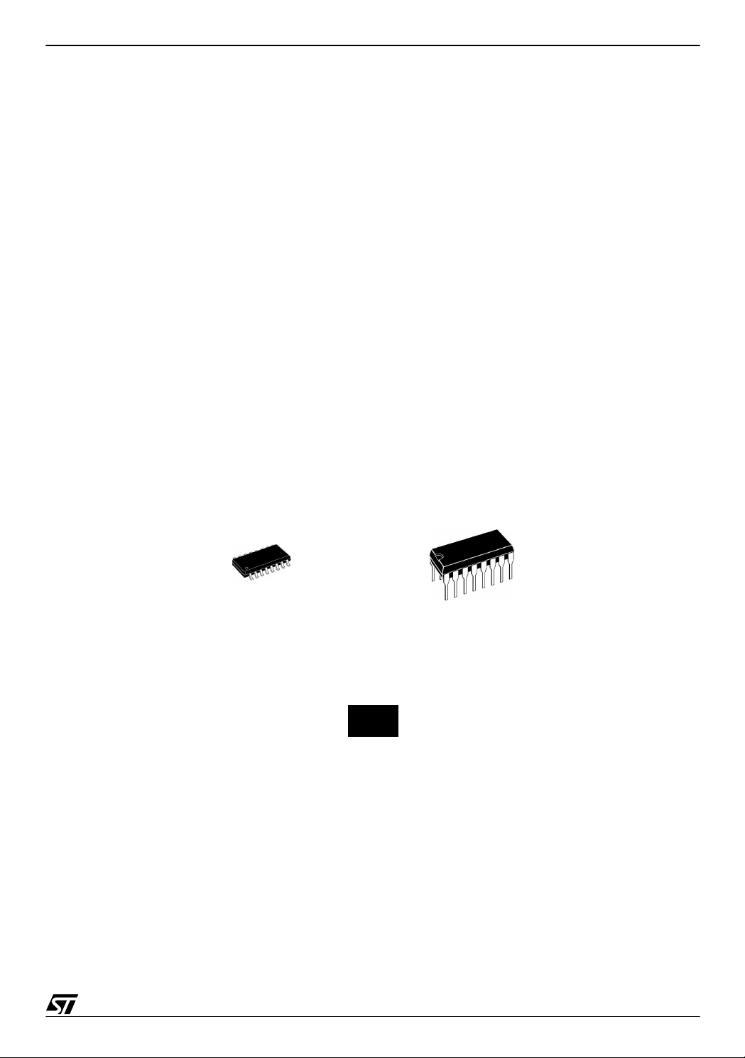
ST7FLITE0 gives you the choice of two small 16-p in packa ges. Yo u can take adva ntage of
this to save area on your PCB.
SO16: 6x9.9mm DIP16:10.92x19.18mm
ST7FLITE0 actual-size footprint of 16-Pin SO Package - Typical: 6mm wide, 9.9mm long
3/26
Page 4

ST7FLITE0 QUICK REFERENCE NOTE
1.3 HIGH ACCURACY INTERNAL 1MHZ RC OSCILLATOR
The ST7Fl ite0 con tains a n i nter nal RC osc illator with a n a ccur acy of 1% for a give n d evice,
temperature and voltage. It must be calibrated to obtain the frequency required in the application. This is done by software writing a calibration value in the RCCR (RC Control Register).
Whenever the ST7FLITE0 microcontroller is reset, the RCCR returns to its default value
(FFh), i.e. each time the device is reset, the calibration value must be loaded in the RCCR.
2
Predefined calibration values are stored in E
PROM for 3.0 and 5V VDD suppl y voltages at
25°C, as shown in the following table.
RCCR Conditions
V
=5V
DD
=25°C
T
RCCR0
RCCR1
A
fRC =1MHz
V
=3V
DD
T
=25°C
A
fRC =700kHz
ST7FLITE09
Address
1000h and
FFDEh
1001h and
FFDFh
ST7FLITE05
Address
FFDEh
FFDFh
If the voltage or temperature conditions change in the application, the frequency may need to
be recalibrated.
Refer to AN1324 “Calibrating The RC Oscillator of the ST7FLITE0 MCU using the Mains
”
for information on how to calibrate the RC frequency using an external reference signal.
Decoupling capacitor f or stab le oscillator
Vdd and Gnd levels impact the stability of the 1% internal RC of the ST7FLITE0. To reach the
most stable oscillation, use decoupling capacitors between Vdd and Gnd pins, at values recommended in the datasheet.
RCCR calibration locations can be W rite Protected
The STVP or InDART tools allow you to prevent uni ntentional write acc ess to the RCCR cali-
bration locations.
1.4 8-BIT A/D CONVERTER WITH INPUT VOLTAGE AMPLIFIER (X8)
The 8-bit A/D converter allows up to 5 channels with multiplexed inputs.
You can take advantage of its internal fixed-gain amplifier (x8) for zooming on low voltage in-
puts. For Vd d=5V , the AD C can the refore c onver t from 0V to 250mV . In this case the ADC
ideal resolution is 2.4mV, equivalent to a 11-bit resolution with input range from 0V to Vdd.
4/26
Page 5

ST7FLITE0 QUICK REFERENCE NOTE
1.5 TRUE E2PROM DATA
The ST7FLITE09 contains an Electrically Erasable Programmable Read-Only Memory which
can be used as a non volatile back-up for storing data. It allows up to 300K Write/Erase cycles
at 25°C.
Main Features
- Up to 32 Bytes programmed in the same cycle
- mono-voltage EEPROM (charge pump)
- Chained erase and programming cycles
- Internal control of the global programming cycle duration
- WAIT mode management
- Read-out protection against piracy
Useful Tips: ST7FLITE05: Emulate Data E2PROM wit h p rogram area
For devices with no Data E2PROM, you can emulate Data EEPR OM
with the XFlash Memory.
For more information, refer to:
AN1477: Emulated Data EEP ROM with XFlash memory
1.6 SAFE PROTECTION AGAINST PIRACY ON DATA E2PROM AND FLASH
2
Data stored in the E
PROM memory, as well as the pr ogram memo ry, are protected against
read-out piracy. This is managed by the option bit “Read-out protection”. Removing this option
by erasing the option byte will cause the whole memory to be erased first.
Flash program mem ory can also be protected aga inst re-w rite opera tion by opti on bit “Flash
Write protection”. When this option is selected, the program memory can never be erased or
programmed again.
5/26
Page 6

ST7FLITE0 QUICK REFERENCE NOTE
1.7 IN-C IRCUI T PROGR AMMING AN D IN- APPLICAT ION P ROGRAMMING CAPABI LITIES
In addition to using a programming tool, the two follow ing modes allow you to program your
ST7LITE0 without removing it from your PCB.
ICP: In-Circuit-Programming: The ICP is the ability to program the Flash memory (FLASH sectors 0 and 1, option byte row and data EEPROM) of a microcontroller using ICC (In-Circuit
Communication) protocol while the device is already plugged-in to the application, but application is not running.
IAP: In-Application-Pro gramm ing: The IAP is the ability to re-progra m the FLAS H memor y
(FLASH sector 1 and data EEPROM) of a microcontroller while the device is al ready pl uggedin to the application and the application is running. As sector 0 contains the software driver to
be able to re-program, it is write protected, therefore not reprogrammable.
In ICP minimum configuration, only 3 wires are needed (ICCCLK, ICCDATA, RESET
user may also use it as a basis to develop its own debugging tool.
Programm ing time:
ICP allows 1kbytes to be programmed/erased in 160ms.
Typical measurements: 1.5k Flash programming time: 315ms
For more information, refer to the Programming Manuals:
. ST7 Flash Programming Reference Manual
. ST7 ICC Protocol Reference Manual
Useful Tips: Sector 0 size configurable by Option Byte
As sector 0 is not re-programmable in IAP programming mode, you
may take advantage of configuring its size to optimize Program
Memory.
By Option Byte, sector 0 size can be set at 0.5 Kbytes, 1 Kbytes, or 1.5
Kbytes.
). The
6/26
Page 7
ST7FLITE0 QUICK REFERENCE NOTE
2 ST7LITE0 DEVEL OPMENT TOOLS
Table 2 shows a summary of available tools for each function.
Table 2. Available Tools
DEBUG
SIMULATE EMULATE
&
PROGRAM
STVD7
Simulator
SOFTWARE
no need ST7MDT10-EMU3 ST7FLITE0-INDART no need ST7MDT10-EPB
HARDWARE
STVD7 STVD7 (included in
ST7FLITE0-INDART
package)
GRAPHIC
DESIGN &
PROGRAM
DEBUG
ST-REALIZERII STVP7
Note: Third-party C-compiler tool chains can be used with STVD7 interface.
2.1 SOFTWARE TOOLS
2.1.1 ST7 Visual Debug IDE - Reference: STVD7
Visual interface for C or Assembler coding, compile, download and debug with ST7 Emulators
or ST7FLITE0-INDART.
Web: http://mcu.st.com
ST7
2.1.2 STVD7 Simulator
Stand-alone tool whi ch al lows to wr ite code, c ompi le, and simul ate an ST 7FLITE0 w ith your
PC your ST7FLITE0.
Web: http://mcu.st.com
ST7
2.1.3 C Compiler toolchains from Cosmic and M etrowerks
- Free evaluation version limited to 1K
- Low-cost lite C compiler limited to 8K
This compilers can be embedded in STVD7 IDE interface, or used through dedicated graph-
ical interfaces.
Web: Cosmic Software Inc.: www.cosmic-software.com
Metrowerks: www.metrowerks.com
2.1.4 ST7 Visual Programmer - Reference: STV P7
2
Visual Interface allowing to program Flash, Data E
PROM, and option bytes. This i s the soft-
ware part of the whole programming tool package. See 4.2.3 for more details.
7/26
Page 8

ST7FLITE0 QUICK REFERENCE NOTE
2.2 HARDWARE TOOLS
2.2.1 In-Circuit Debugging Kit - Reference: ST7FLITE0-INDART
ST7FLITE0-INDART includes a full-featured experiment board, an in-circuit programming
utility, and all tools required to develop custom embedded applications, at low cost. 100% of
electrical characteristics are guaranteed by use of a standard chip, not bondout chip.
ST7FLITE0-INDART contains STVD7 graphical interface, C compiler and assembl er.
Debugging capabilit ies: Real-time emulation, breakpoints, step capabilities , read/write
memory and registers.
2
Programming capabilities: Blank-check, Program, Read, Verify Flash, E
PROM memory and
Option Bytes.
Notes:
1. It can be ordered from ST, or directly from Softec. Softec reference: inDART-ST7FLITE0
2. No power supply is delivered with this kit. A typical 5V may be used.
Web: http://www.softecmicro.com/indart-st7flite0.html
e-mail: info@softecmicro.com
2.2.2 ST Emulator - Reference: ST7MDT10-EMU3
Advanced development tool including:
- Real-time emulator (Advanced breakpoints management (through Bus Event Machine),
256K real-time trace recording, read/write on the fly through Watch and Memory windows,
Performance analysis)
- STVD7 User Interface
- Set of probes for Lite family packages.
- Parallel interface cable to PC
- Power Supply
Note: the ST Emulator cannot program parts. Therefore, a separate devic e programmer is r e-
quired (as ST7 Programming tool (see 4.2.3))
Web: http://mcu.st.com
ST7
8/26
Page 9

ST7FLITE0 QUICK REFERENCE NOTE
2.2.3 ST Programming tool - Reference: ST7MDT10-EPB
2
Main features: Blank-check, Program, Read, Verify Flash, E
PROM memory and Option
Bytes.
ICP programming mode is supported. All Lite0 packages included.
This is done through STVP7: ST7 Visual Programmer. Visual Interface allowing to program
2
Flash, Data E
Web: http://mcu.st.com
PROM, and option bytes.
ST7
2.2.4 ST Graphic Design and Debu g - Reference: STREALIZER- II
The ST Realizer allows you to graphically design applications for the ST7 microcontroller
family, without any prerequisite knowledge in assembler program ming. With a single click,
using the powerful graphics editor and compiler, you can generate complete software applications for the ST7FLite0.
Main features: schematic-based Design, Analysis, Simulator for debugging
Web: http://mcu.st.com
ST7
9/26
Page 10

ST7FLITE0 QUICK REFERENCE NOTE
3 START TODAY
1) Go to ST's website (http://mcu.st.com) and download:
– STVD7 software
and these items:
– ASM/LYN software
– C osmic C compiler Demo software
– Metrowerks C compiler software
– ST Visual Programmer
2) Install all software and follow “Getting Started” in STVD7.
3) Copy certain files for the “Getting Started” example and create your own project in STVD7.
4) Order tools:
– EMU - ST's or inDART
– EPB
– C compiler - Cosmic or Metrowerks
10/26
Page 11

ST7FLITE0 QUICK REFERENCE NOTE
4 ST7FLIT E0 8-BIT MCU - EASY REF E RENCE
Figure 1. Pinout Table 3. Device Summary
Features ST7FLITE09 ST7FLITE05
Program Memory
1
ei0
V
SS
V
DD
RESET
/AIN0/PB0
SS
SCK/AIN1/PB1
MISO/AIN2/PB2
MOSI/AIN3/PB3
CLKIN/AIN4/PB4
HS: 20 mA High Sink Capability
eix: Associated External Inte rrupt Vector
16
2
15
3
14
ei3
13
4
12
5
11
6
7
10
ei2
8
ei1
9
PA0 (HS)/LTIC
PA1 (HS)
PA2 (HS)/ATPWM0
PA3 (HS)
PA4 (HS)
PA5 (HS)/ICCDATA
PA6/MCO/ICCCLK
PA7
(Bytes)
RAM/Stack (Bytes) 128/64 128/64
Data EEPROM
(Bytes)
Peripherals
Operating Supply 2.4 V to 5.5 V
CPU Frequency 1 MHz RC 1% PLL x4/8MHz
Operating Tempera-
ture
Table 4. Pin Chart
Pin Name Main Function Alternate Function
1.5K FLASH 1.5K FLASH
128 -
Lite Timer w/ Watchdog, Autore-
load Timer w/ 1
PWM, SPI, 8-bit ADC w/ Op-Amp
-40 C to +85 C (-40 C to +105/125
C Optional)
1V
2V
SS
DD
3 RESET
4SS
/AIN0/PB0 PORT B0 ADC Analog Input 0 or SPI Slave Select (active low)
Ground
Main Power Supply
Top-Priority Non Maskable Interrupt (active low)
5 SCK/AIN1/PB1 PORT B1 ADC Analog Input 1 or SPI Serial Clock
6 MISO/AIN2/PB2 PORT B2 ADC Analog Input 2 or SPI Master In/Slave Out Data
7 MOSI/AIN3/PB3 PORT B3 ADC Analog Input 3 or SPI Master Out/Slave In Data
8 CLKIN/AIN4/PB4 PORT B4 ADC Analog Input 4 or External Clock Input
9 PA7 PORT A7
10 PA6 /MCO/ICCCLK PORT A6 Main Clock Output or In-Circuit Communication Clock
11 PA5 (HS)/ICCDATA PORT A5 In-Circuit Communication Data
12 PA4 (HS) PORT A4
13 PA3 (HS) PORT A3
14 PA2 (HS)/ATPWM0 PORT A2 Auto-Reload Timer PWM0
15 PA1 (HS) PORT A1
16 PA0 (HS)/LTIC PORT A0 Lite Timer Input Capture
11/26
Page 12

ST7FLITE0 QUICK REFERENCE NOTE
Table 5. Instruction Set
Mnemonic Description Operation Dest. Source Flags
ADC d, s Add with carry, s to d d ⇐ d + s + C A mem H, N, Z, C
⇐
ADD d, s Add s to d d
AND d, s Logical AND (d with s) d
BCP s, d Bit compare A, mem {N, Z}
BRES d, b Bit reset d d
BSET d, b Bit set d d
BTJF d, b, rel Jump if bit is false (0) PC
BTJT d, b, rel Jump if bit is true (1) PC
CALL d Call subroutine PUSH (PC + length); PC
CALLR d Call subroutine relative PUSH (PC + length); PC
CLR d Clear d d
CP d, s Arithmetic compare {N, Z, C}
CPL d Logical complement of d d
DEC d Decrement d d
HALT Halt I
INC d Increment d d
IRET Interrupt routine return POP CC, A, X, PC - - H, I, N, Z , C
d + s A mem H, N, Z, C
⇐
d AND s A mem N, Z
⇐
s AND d A mem N, Z
⇐
d AND (2b)mem--
⇐
d OR (2b)mem--
⇐
PC + rel IF (d AND (2b)) = 0 mem - C
⇐
PC + rel IF (d AND (2b)) ≠ 0mem - C
⇐
dmem--
⇐
PC + d mem - -
⇐
0
⇐
TEST (d - s) reg mem N, Z, C
⇐
d XOR FFh
⇐
d - 1
⇐
0--I = 0
⇐
d + 1
reg,
mem
reg,
mem
reg,
mem
reg,
mem
- N = 0, Z = 1
- N, Z, C = 1
-N, Z
-N, Z
⇐
JP d Absolute jump PC
JRA d Jump relative always PC
JRT d Jump relative if true P C
JRF d Never jump - mem - JRIH d Jump Relative if Port INT pin = 1 PC
JRIL d Jump Relative if Port INT pin = 0 PC
JRH d Jump Relative if H = 1 PC
JRNH d Jump Rela t i ve if H = 0 PC
JRM d Jump Rela tive if I = 1 PC
JRNM d Jump Relative if I = 0 PC
JRMI d Jump Relative if N = 1 PC
JRPL d Jump Relative if N = 0 PC
JREQ d Jump Relative if Z = 1 PC
JRNE d Jump Relative if Z = 0 PC
12/26
dmem--
⇐
PC + d mem - -
⇐
PC + d mem - -
⇐
PC + d IF interrupt line high mem - -
⇐
PC + d IF interrupt line low mem - -
⇐
PC + d IF H = 1 mem - -
⇐
PC + d IF H = 0 mem - -
⇐
PC + d IF I = 1 me m - -
⇐
PC + d IF I = 0 me m - -
⇐
PC + d IF N = 1 mem - -
⇐
PC + d IF N = 0 mem - -
⇐
PC + d IF Z = 1 mem - -
⇐
PC + d IF Z = 0 mem - -
Page 13

ST7FLITE0 QUICK REFERENCE NOTE
Table 5. Instruction Set
Mnemonic Description Operation Dest. Source Flags
JRC d Jump Relative if C = 1 PC ⇐ PC + d IF C = 1 mem - -
⇐
JRNC d Jump Rela t i ve if C = 0 PC
JRULT d Jump Relative if C = 1 PC
JRUG E d Jump Relative if C = 0 PC
JRUGT d Jump Relative if (C + Z) = 0 PC
JRULE d Jump Rela tive if (C + Z) = 1 PC
LD d, s Load s in d d
MUL d, s Multiply d by s d:s
NEG d Negate d (logical 2-complement) d
NOP No operation - - - -
OR d, s Logical OR (d with s) d
POP d Pop from the Stack d
PC + d IF C = 0 mem - -
⇐
PC + d IF C = 1 mem - -
⇐
PC + d IF C = 0 mem - -
⇐
PC + d IF (C OR Z) = 1 mem - -
⇐
PC + d IF (C OR Z) = 0 mem - -
⇐
s
⇐
d * s A, X, Y A, X, Y H = 0, C = 0
⇐
(d XOR FFh) + 1
⇐
d OR s A mem N, Z
⇐
(++SP) reg, CC - H, I, N, Z, C
reg,
mem
reg,
mem
mem,
reg
- N, Z, C
N, Z
⇐
PUSH d Push onto the Stack (SP- -)
RCF Reset carry flag C
d-reg, CC-
⇐
0--C = 0
RET Subroutine return POP PC - - -
⇐
RIM Reset interrupt mask I
RLC d Rotate left through carry
RRC d Rotate right through carry
RSP Reset Stack pointer SP
SBC d, s Subtract s from d with carry d
SCF Set carry flag C
SIM Set interrupt mask I
SLA d
Shift left arithmetic (equal to SLL
1)
SLL d Shift left logical
SRA d
Shift right arithmetic (equal to
SRL 1)
SRL d Shift right logical
SUB d, s Subtract s from d d
SWAP d Swap nibbles d (7:4)
TNZ d Test for negative and zero {N, Z}
0--I = 0
C ← 70
C→70
⇐
reset value - - -
⇐
d - s - C A mem N, Z, C
⇐
1--C = 1
⇐
1--I = 1
C←70←0
C←70←0
70→0
0→70→C
⇐
d - s A mem N, Z, C
⇔
d (3:0)
⇐
TEST (d)
reg,
mem
reg,
mem
reg,
mem
reg,
mem
reg,
mem
reg,
mem
reg,
mem
reg,
mem
- N, Z, C
- N, Z, C
- N, Z, C
- N, Z, C
- N, Z, C
- N = 0, Z, C
-N, Z
-N, Z
13/26
Page 14

ST7FLITE0 QUICK REFERENCE NOTE
Table 5. Instruction Set
Mnemonic Description Operation Dest. Source Flags
⇐
PC + 1; PUSH PC, X, A, CC;
TRAP Software trap
WFI Wait for interrupt I ⇐ 0--I = 0
XOR d, s Logical exclusive OR (d with s) d
PC
⇐
trap vector
PC
⇐
d XOR s A mem N, Z
--I = 1
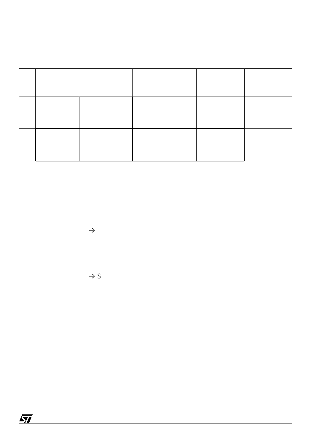
Figure 2. Block Diagram
8-BIT
CORE
ALU
POWER
SUPPLY
CONTROL
(LVD + AVD)
LITE TIMER
+
WATCHDOG
12-BIT
AUTORELOAD
TIMER
FLASH
MEMORY
(1.5K Bytes)
ST7LITE
CORE
1 MHz RC OSC
+
PLL 4x or 8x
RAM
(128 Bytes)
EXTERNAL
CLOCK
DATA
EEPROM
(128 Bytes)
SPI
8-BIT ADC
+
AMPLI x8
PORT A
PORT B
14/26
Page 15

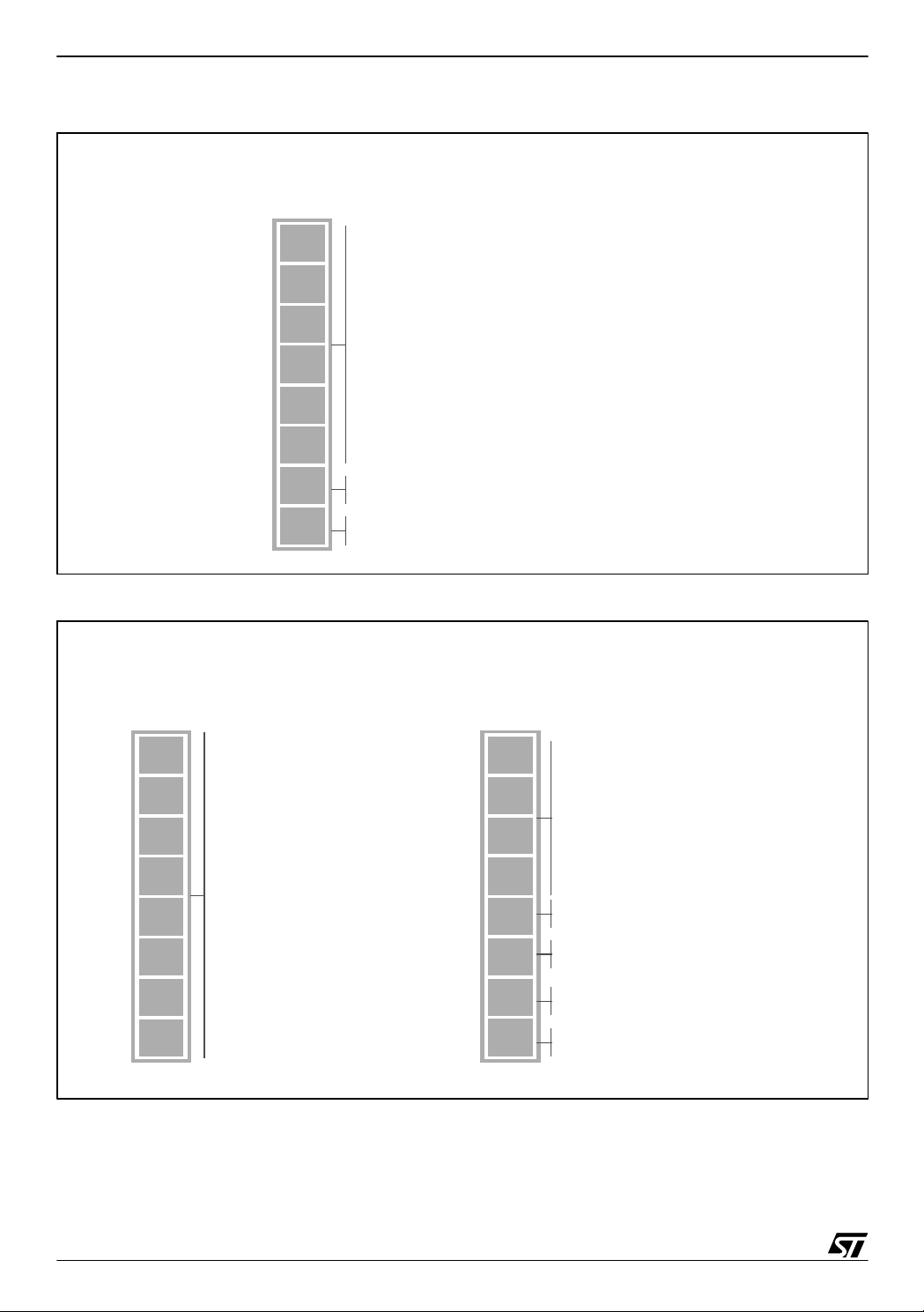
Figure 3. Me mory Map
0000h
007Fh
0080h
00FFh
0100h
0FFFh
1000h
107Fh
1080h
F97Fh
F980h
F9FFh
FA00h
FFDFh
FFE0h
FFFFh
Interrupt and Reset Vectors
HW Registers
RAM
(128 B yte s )
Reserved
Datas EEPROM
(128 B yte s )
Reserved
BootRom
(128 B yte s )
FLASH Memory
(1.5K Bytes)
0080h
00BF h
00C0h
00FFh
ST7FLITE0 QUICK REFERENCE NOTE
Short Addressing RAM
Address
Vector
FFE0h-FFE1h 13 - Not Used
FFE2h-FFE3h 12 SPI SPI Peripheral Interrupts
FFE4h-FFE5h 11 LITE TIMER LITE TIMER RTC Interrupt
FFE6h-FFE7h 10 LITE TIMER LITE TIMER Input Capture Interrupt
FFE8h-FFE9h 9 AT TIMER AT TIMER Overflow Interrupt
FFEAh-FFEB h 8 A T TIMER AT TIMER O utput Compare Interrupt
FFECh-FFEDh 7 SI AVD Interrupt
FFEEh-FFEFh 6 - Not Used
FFF0h-FFF1h 5 - Not Used
FFF 2 h-FFF3h 4 ei3 Exter nal Interrup t 3
FFF 4 h-FFF5h 3 ei2 Exter nal Interrup t 2
FFF 6 h-FFF7h 2 ei1 Exter nal Interrup t 1
FFF 8 h-FFF9h 1 ei0 Exter nal Interrup t 0
FFFAh-FFFBh 0 - Not Used
FFFCh-FFFDh - TRAP Software Interrupt
FFFEh-FFFFh - RESET Reset
(Zero Page)
Stack
(64 Bytes)
Source
N Description
Block
Register
Label
SPICSR
LTCSR
LTCSR
ATCSR
PWM0CSR
SICSR
-
N/A
N/A
N/A
N/A
N/A
Priority
Lowest
HighestN/A
Figure 4. Option Bytes
DEFAULT VALUE = FFFCh
PLL
15
x4x8
PLL
OFF
OSC
LVD1
LVD0
WDG
OPTION BYTE 1
SW
WDG
8
HALT
7
1
1
1
1
SEC1
SEC0
FMP
OPTION BYTE 0
R
FMP
0
W
0 = PLL x 4
1 = PLL x 8
0 = PLL ENABLED
1 = PLL DISABLED
RESERVED
0 = RC OSCILLATOR ON
1 = RC OSCILLATOR OFF
00 = LOWEST VOLTAGE THRESHOLD (~2.8 V)
01 = MEDIUM VOLTAGE THRESHOLD (~3.5 V)
10 = HIGHEST VOLTAGE THRESHOLD (~4.1 V)
11 = L VD OFF
0 = HARDWARE WATCHDOG
1 = SOFTWARE WATCHDOG
0 = NO RESET GENERATION IN HALT
1 = RESET GENERATION IN HALT
RESERVED, MUST BE SET TO 1
00 = SECTOR 0 SIZE = 0.5K BYTES
01 = SECTOR 0 SIZE = 1K BYTES
10 = SECTOR 0 SIZE = 2K BYTES
11 = SECTOR 0 SIZE = 4K BYTES
0 = READ-OUT PROTECTION OFF
1 = READ-OUT PROTECTION ON
0 = FLASH WRITE PROTECTION OFF
1 = FLASH WRITE PROTECTION ON
15/26
Page 16

ST7FLITE0 QUICK REFERENCE NOTE
Figure 5. CPU Registers
70
70
70
7
015 8
70
111 INZCH
HALF CARRY
INTERRUPT MASK
NEGATIVE
ZERO
CARRY
15 8
00000000
7 0
SP SP SP
SP
1
SP
1
543210
SP
Figure 6. Typical In-Circuit Programming Interface
ACCUMULATOR
RESET VALUE = XXh
X INDEX REGISTER
RESET VALUE = XXh
Y INDEX REGISTER
RESET VALUE = XXh
PROGRAM COUNTER
RESET VALUE =
RESET VECTOR @ FFFEh-FFF Fh
CONDITION CODE REGISTE R
RESET VALUE = 111X1XXXb
STACK POINTER
RESET VALUE = STACK HIGHER ADDRESS
V
DD
RESET
ICCDATA
ICCCLK
CLKIN
NC
V
PP
RESET
ICCCLK
ICCDATA
SEE DATASHEET FOR MORE
INFORMATION
APPLICATION
HE10
CONNECTOR
OSC_CLK
V
DD
GND
GND
GND
1
16/26
Page 17

Table 6. Port Implementation
ST7FLITE0 QUICK REFERENCE NOTE
Standard Ports
(PA6:1, PB4, PB2:0)
(PA7, PA0, PB3, PB0, with Pull-Ups
Interrupt Ports
Mode DDR OR Mode DDR OR
Floating Input 0 0 Floating Input 0 0
Pull-Up Input 0 1 Pull-Up Interrupt Input 0 1
Open Drain Output 1 0 Open Drain Output 1 0
Push-Pull Output 1 1 Push-Pull Output 1 1
Figure 7. Port A
70
D7
D6
D5
D3 D2 D1
D4
PORT A DATA REGISTER
D0
PADR (@ 0000h, Read/Write)
RESET VALUE = 00h
70
DD7
DD6
DD5
DD3 DD2 DD1 DD0
DD4
PORT A DATA DIRECTION REGISTER
PADDR (@ 0001h, Read/Write)
RESET VALUE = 00h
70
O7
O6
O5
O3 O2 O1
O4
PORT A OPTION REGISTER
O0
PADR (@ 0002h, Read/Write)
RESET VALUE = 40h
Figure 8. Port B
70
000
D3 D2 D1
D4
PORT B DATA REGISTER
D0
PBDR (@ 0003h, Read/Write)
RESE T VALUE = 00h
70
000
DD3 DD2 DD1 DD0
DD4
PORT B DATA DIRECTION REGISTER
PBDDR (@ 0004h, Read/Write)
RESE T VALUE = 00h
70
000
O3 O2 O1
O4
PORT B OPTION REGISTER
O0
PBDR (@ 0005h, Read/Write)
RESE T VALUE = 00h
17/26
Page 18

ST7FLITE0 QUICK REFERENCE NOTE
Figure 9. Lite T i mer
LITE TIMER CONTROL STATUS REGISTER
LTCSR (@ 000Bh, Read/Write)
RESET VALUE = 0X000000b
7
0
ICIE
ICF
TB
TBIE
TBF
WDG
RF
WDGE
WDGD
0 = INPUT CAPTURE INTERRUPT DISABLED
1 = INPUT CAPTURE INTERRUPT ENABLED
0 = NO INPUT CAPTURE
1 = AN INPUT CAPTURE HAS OCCURED
0 = TIMEBASE PERIOD = t
1 = TIMEBASE PERIOD = t
0 = TIMEBASE INTERRUPT DISABLED
1 = TIMEBASE INTERRUPT ENABLED
0 = NO COUNTER OVERFLOW
1 = A COUNTER OVERFLOW HAS OCCURED
0 = NO WATCHDOG RESET OCCURED
1 = RESET WDG (W), A WDG RESET OCCURED (R)
0 = WATCHDOG DISABLED
1 = WATCHDOG ENABLED
0 = WATCHDOG RESET NOT DELAYED
1 = WATCHDOG RESET DELAYED
Figure 10. ITC
EXTERNAL INT. CONTROL REGISTER
EICR (@ 0037h, Read/Write)
RESE T VALUE = 00h
OSC
OSC
* 8000
* 16000
LITE TIMER INPUT CAPTURE REGISTER
LTISR (@ 000Ch, Read Only)
RESET VALUE = 00h
7
ICR7
ICR6
ICR5
ICR4
INPUT CAPTURE VALUE
ICR3
ICR2
ICR1
ICR0
0
18/26
IS31
7
IS30
IS21
IS20
IS11
IS10
IS01
00 = ei3 SENS. = FALLING EDGE & LOW LEVEL
01 = ei3 SENS. = RISING EDGE ONLY
10 = ei3 SENS. = FALLING EDG E ONLY
11 = ei3 SENS. = RISING AND FALLING EDGE
00 = ei2 SENS. = FALLING EDGE & LOW LEVEL
01 = ei2 SENS. = RISING EDGE ONLY
10 = ei2 SENS. = FALLING EDG E ONLY
11 = ei2 SENS. = RISING AND FALLING EDGE
00 = ei1 SENS. = FALLING EDGE & LOW LEVEL
01 = ei1 SENS. = RISING EDGE ONLY
10 = ei1 SENS. = FALLING EDG E ONLY
11 = ei1 SENS. = RISING AND FALLING EDGE
00 = ei0 SENS. = FALLING EDGE & LOW LEVEL
01 = ei0 SENS. = RISING EDGE ONLY
IS00
0
10 = ei0 SENS. = FALLING EDG E ONLY
11 = ei0 SENS. = RISING AND FALLING EDGE
Page 19

Figure 11. Auto Reload Timer
ST7FLITE0 QUICK REFERENCE NOTE
TIMER CONTROL STATUS REGISTER
ATCSR (@ 000Dh, Read/Write)
RESET VALUE = 00h
0
7
0
0
CK1
CK0
OVF
OVFIE
CMPIE
0
COUNTER REGISTER LOW
CNTRL (@ 000Fh, Read Only)
RESET VALUE = 00h
RESERVED, MUST BE SET TO 0
00 = COUNTER CLOCK SELECTION = OFF
01 = COUNTER CLOCK SELECTION = f
10 = COUNTER CLOCK SELECTION = f
0 = NO COUNTER OVERFLOW OCCURED
1 = A COUNTER OVERFLOW OCCURED
0 = OVF INTERRUPT DISABLED
1 = OVF INTERRUPT ENABLED
0 = CMPF INTERRUPT DISABLED
1 = CMPF INTERRUPT ENABLED
LTIMER
CPU
AUTO RELOAD REGISTER HIGH
ATRH (@ 0010h, Read/Write)
RESET VALUE = 00h
COUNTER REGISTER HIGH
CNTRH (@ 000Eh, Read Only)
RESET VALUE = 00h
0
7
0
RESERVED
0
0
CN11
CN10
CN9
CN8
0
AUTO RELOAD REGISTER LOW
ATRL (@ 0011h, Read/Write)
RESET VALUE = 00h
COUNTER VALUE
CN7
7
CN6
CN5
CN4
CN3
CN2
CN1
CN0
0
COUNTER VALUE
7
0
0
0
RESERVED
0
0
ATR11
ATR10
AUTO RELOAD VALUE
ATR9
ATR8
7
ATR7
ATR6
ATR5
ATR4
AUTO RELOAD VALUE
ATR3
ATR2
ATR1
ATR0
0
19/26
Page 20

ST7FLITE0 QUICK REFERENCE NOTE
Figure 12. Auto Reload Timer (cont’d)
PWM OUTPUT CONTROL REGISTER
PWMCR (@ 0012h, Read/Write)
RESET VALUE = 00h
7
0
0
0
0
RESERVED, MUST BE SET TO 0
0
0
0
OE0
0
PWM0 CONTROL/STATUS REGISTER
PWM0CSR (@ 0013h, Read/Write)
RESET VALUE = 00h
0
7
0
0
0
0
0
OP0
0
CMPF0
0 = OUTPUT COMP. MODE EN., PWM MODE DIS.
1 = OUTPUT COMP. MODE DIS., PWM MODE EN.
RESERVED, MUST BE SET TO 0
0 = PWM0 SIGNAL NOT INVERTED
1 = PWM0 SIGNAL INVERTED
0 = UPCOUNTER VAL. DOESN T MATCH DCR VAL.
1 = UPCOUNTER VALUE MATCHES DCR VALUE
20/26
Page 21

Figure 13. Auto Reload Timer (cont’d)
ST7FLITE0 QUICK REFERENCE NOTE
PWM0 DUTY CYCLE REGISTER HIGH
DCR0H (@ 0017h, Read/Write)
RESET VALUE = 00h
0
7
0
RESERVED
0
0
DCR11
DCR10
PWM DUTY CYCLE VALUE
DCR9
DCR8
0
Figure 14. FLA SH
7
0
FLASH CONTROL/STATUS REGISTER
FCSR (@ 002Fh, Read/Write)
RESET VALUE = 00h
PWM0 DUTY CYCLE REGISTER LOW
DCR0L (@ 0018h, Read/Write)
RESE T VALUE = 00h
DCR7
DCR6
DCR5
DCR4
PWM DUTY CYCLE VALUE
DCR3
DCR2
DCR1
DCR0
0
7
0
0
0
0
OPT
LAT
PGM
0
RESERVED, MUST BE SET TO 0
0 = ICP MODE PROGRAM MEMORY ACCESS
1 = ICP MODE OPTION BYTE ACCESS
0 = READ MODE
1 = WRITE MODE
0 = PROGR. FINISHED OR NOT YET STARTED
1 = PROGRAMMING CYCLE IN PROGRESS
21/26
Page 22

ST7FLITE0 QUICK REFERENCE NOTE
Figure 15. EEPROM
EEPROM CONTROL/STATUS REGIS TER
E2CSR (@ 0030h, Read/Write)
RESET VALUE = 00h
7
0
0
0
0
0
0
RESERVED, MUST BE SET TO 0
E2PGM
0
E2LAT
0 = READ MODE
1 = WRITE MODE
0 = PROGR. FINISHED OR NOT YET STARTED
1 = PROGRAMMING CYCLE IN PROGRESS
22/26
Page 23

Figure 16. SPI
ST7FLITE0 QUICK REFERENCE NOTE
SPI DATA I/O REGISTE R
SPIDR (@ 0031h, Read/Write)
RESE T VALUE = XXh
D7
7
D6
D5
D4
SPI DATA
D3
D2
D1
D0
0
SPI CONTROL/STATUS REGISTER
SPICSR (@ 0033h, Read Only)
RESE T VALUE = 00h
SPI CONTROL REGI STER
SPICR (@ 0032h, Read/Write)
RESET VALUE = 0Xh
7
SPIE
SPE
SPR2
MSTR
CPOL
CPHA
SPR1
0 = INTERRUPT DISABLED
1 = INT. GEN. WHEN SPIF = 1 O R MODF = 1
0 = I/O PORT CONNECTED TO PINS
1 = SPI ALT. FUNCTION CONNECTED TO PINS
0 = DIVIDER BY 2 ENABLED
1 = DIVIDER BY 2 DISABLED
0 = SLAVE MODE SELECTED
1 = MASTER MODE SELECTED
0 = STEADY STATE IS LOW
1 = STEADY STATE IS HIGH
0 = DATA CAPTURE ON 1ST CLOCK TRANSITION
1 = DATA CAPTURE ON 2ND CLOCK TRANSITION
00 = SERIAL PERIPHERAL RATE = f
01 = SERIAL PERIPHERAL RATE = f
0
SPR0
10 = SERIAL PERIPHERAL RATE = f
11 = SERIAL PERIPHERAL RATE = f
CPU
CPU
CPU
CPU
/ 8
/ 16
/ 64
/ 128
7
0
SPIF
WCOL
OVR
MODF
0
SOD
SSM
SSI
0 = DATA TRANSFER IN PROGRESS
1 = DATA TRANSFER COMPLETED
0 = NO WRITE COLLISIONS DETECTED
1 = A WRITE COLLISION HAS BEEN DETECTED
0 = NO OVERRUN ERRORS
1 = AN OVERRUN ERROR HAS BEEN DETECTED
0 = NO MASTER MODE FAULTS DETECTED
1 = A MASTER MODE FAULT HAS BEEN DETECTED
RESERVED, MUST BE SET TO 0
0 = SPI OUTPUT NOT DISABLED
1 = SPI OUTPUT DISABLED
0 = HARDWARE MODE
1 = SOFTWARE MODE
0 = SLAVE SELECTED
1 = SLAVE NOT SELECTED
23/26
Page 24
ST7FLITE0 QUICK REFERENCE NOTE
Figure 17. MCC
MAIN CLOCK CNTRL/STATUS REGISTER
MCCSR (@ 0038h, Read/Write)
RESET VALUE = 00h
0
7
0
0
RESERVED, FORCED BY HARDWARE TO 0
0
0
0
MCO
SMS
0
Figure 18. Clock and Reset
RC CONTROL REGISTER
RCCR (@ 0039h, Read/Write)
RESET VALUE = FFh
CR7
7
CR6
CR5
CR4
CR3
CR2
CR1
CR0
0
RC OSC I LLATOR FREQUENCY
ADJUSTMENT BITS
0 = MAIN CLOCK OUT DISABLED
1 = MAIN CLOCK OUT ENABLED
0 = NORMAL MODE (f
1 = SLOW MODE (f
CPU
CPU
= f
= f
OSC
OSC
/32)
SI CONTROL/STATUS REGISTER
SICSR (@ 003Ah, Read Only)
RESET VALUE = 00h
0
7
0
RESE RVED, MUST BE SET T O 0
0
0
LOC
KED
LVD
RF
AVD
F
AVD
0
IE
0 = PLL NOT LOCKED
1 = PLL LOCKED
LVD RESET FLAG
0 = V
1 = V
0 = AVD INTERRUPT DISABLED
1 = AVD INTERRUPT ENABLED
)
OVER V
DD
UNDER V
DD
THRESHOLD
IT+
THRESHOLD
IT+
24/26
Page 25

Figure 19. ADC
ST7FLITE0 QUICK REFERENCE NOTE
ADC CONTROL/STATUS REGISTER
ADCCSR (@ 0034h, Read/Write)
RESET VALUE = 00h
EOC
7
SPEED
ADON
0
0
CH2
CH1
CH0
0
ADC AMPLIFIER CONTROL REGISTER
ADCAMP (@ 0036h, Read/Write)
RESET VALUE = 00h
0 = CONVERSION NOT COMPLETE
1 = CONVERSION COMPLETE
ADC CLOCK SPEED
(USED TOGETHER WITH THE SLOW BIT)
ADC DISABLED
ADC ENABLED
RESERVED, MUST BE SET TO 0
000 = AIN0 SELECTED
001 = AIN1 SELECTED
010 = AIN2 SELECTED
011 = AIN3 SELECTED
100 = AIN4 SELECTED
ADC DATA REGISTER
ADCDR (@ 0035h, Read Only)
RESET VALUE = XXh
D7
7
D6
D5
D4
ANALO G CONVERTED VALUE
D3
D2
D1
D0
0
7
0
0
0
0
0
SLOW
AMPON
0
0
RESERVED, FORCED BY HARDWARE TO 0
ADC CLOCK SPEED
(USED TOGETHER WITH THE SPEED BIT)
0 = AMPLIFIER OFF
1 = AMPLIFIER ON (f
RESERVED, FORCED BY HARDWARE TO 0
MUST BE ≤ 2 MHz)
ADC
25/26
Page 26

ST7FLITE0 QUICK REFERENCE NOTE
“THE PRESENT NOTE WHICH IS FOR GUIDANCE ONLY AIMS AT PROVIDING CUSTOMERS WITH
INFORMATION REGARDING THEIR PRODUCTS IN ORDER FOR THEM TO SAVE TIME. AS A RESULT, STMICROELECTRONICS SHALL NOT BE HELD LIABLE FOR ANY DIRECT, INDIRECT OR
CONSEQUENT IAL DAMAGES WI TH RESPECT TO ANY CLAIMS ARIS ING FROM THE CONTENT OF
SUCH A NOTE AND/OR THE USE MADE BY CUSTOMERS OF THE INFORMATION CONTAINED
HEREIN IN CONNEXION WITH THEIR PRODUCTS.”
Information furnished is believed to be accurate and reliable. However, STMicroelectronics assumes no responsibility for the consequences
of use of such information nor for any infringement of patents or other rights of third parties which may result from its use. No license is granted
by implic ation or otherwise under any patent or patent ri ghts of STM i croelectr oni cs. Spec i fications mentioned i n this publication are subje ct
to change without notice. This publication supersedes and replaces all information previously supplied. STMicroelectronics products are not
authorized for use as cri tical comp onents in life support dev i ces or systems wi thout the express written approv al of STMicroel ectronics.
The ST logo is a registered trademark of STMicroelectronics
2003 STMicroelectronics - All Rights Reserved.
STMicroelectronics Group of Compan i es
http://www.s t. com
Purchase of I
2
C Components by STMicroelectronics conveys a license under the Philips I2C Patent. Rights to use the se components in an
2
C system i s granted pro vi ded that the sy stem conforms to the I2C Standard Specification as defined by Philips.
I
Australi a - B razil - Canada - China - Finl and - France - Germany - Hong Kong - Ind ia - Israel - Italy - Japan
Malaysi a - M al ta - Morocco - Singapore - Spain - Sw eden - Switz erland - United Kingdom - U.S.A.
26/26
 Loading...