

Page 1

AN1502
APPLICATION NOTE
EMULATED DATA EEPRO M WITH ST7 HDFLASH MEMORY
by Microcontroller Division Applications
INTRODUCTION
When the data EEPROM is not available in a ST7 device, it can be emulated by the HDFlash
memory with some re strictions. This App lication Note descri bes how to emulate thi s feature
with a ST72F521 device and the restrictions this emulation implies.
Data EEPROM can be emulated in all HDFlash devices.
AS HDFlash is a dual voltage FLASH memory, the 12-volt programming voltage must be
provided on the application board (a pull-down on ICPSEL on the application board is
advised).
For more i nforma tio n con cerning S T7 pr ogra mmi ng, a .z ip file is include d wi th th e c omp lete
corresponding code for the ST72F521, visit our web site at www.st.com.
AN1502/0202 1/7
1
Page 2
EMULATED DATA EEPROM WITH ST7 HD FL ASH MEMORY
1 PRINCIPLE
Two different implementations can be distinguished:
■ Assuming that it is possible to limit the data EEPROM byte values to 00h..FEh (as FFh is the
default HDFlash erased value), the principle of thi s emulation is to reserve n bytes in the
HDFlash for each emulated data EEPROM byte whic h has to be cycled n times. With this
solution FFh value can not be used.
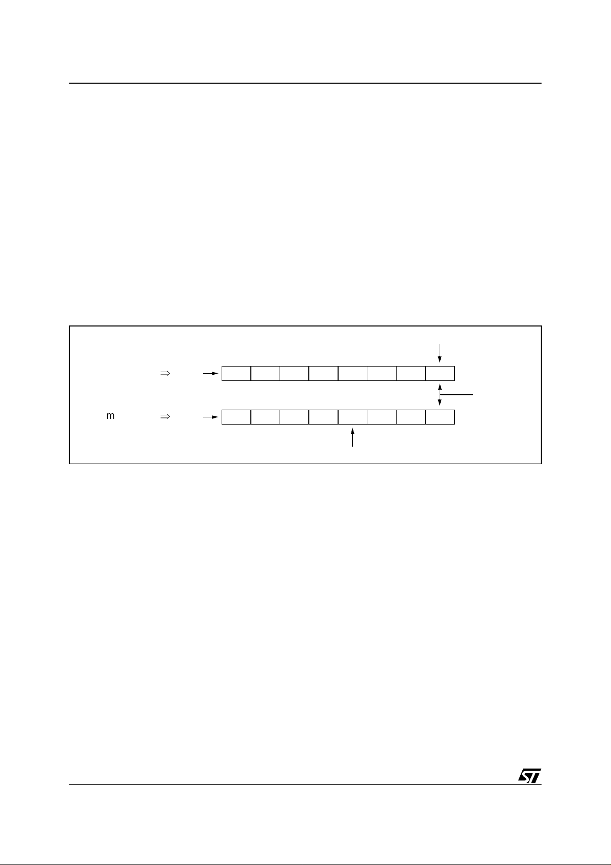
As shown in Figure 1., a “ptr” pointer gives the access to the emulated data EEPROM byte.
– For a read operation, from “ptr” address, read the first data byte not equal to FFh to get the
current value.
– For a write operation, from “ptr” address, look for the last data byte equal to FFh and then
write the new value at this location using the HDFlash “Byte programming” Embedded
Command (same as IAP method).
Figure 1. HDFlash Emulated Data EEPROM (value in 00h..FEh)
current value
INITIAL STATE
mthSTATE
■ Assuming no limitation for the data EEPROM byte values (00h..FFh), each byte value will
⇒
⇒
ptr
ptr
FFh FFh ... FFh FFh ... FFh val1
initial value
FFh FFh ... FFh valm ... val2 val1
current value
need 2 byte locations. The first one will determine if it is the current value (example: 00h =
current value, FFh = not yet used v alue) and the seco nd one will contain the c urrent byte
value. So the principle of this emulation is to reserve 2xn bytes in the HDFlash for each
emulated data EEPROM byte whi ch has to be cycled n times.
As shown in Figure 2., a “ptr” pointer gives the access to the emulated data EEPROM byte.
– For a read operation, from “ptr” addr ess, r ead the first data byte not equal to FFh (equal to
00h), the current value is the next adjacent byte.
– For a write operation, from “ptr” address, look for the last data byte equal to FFh and then
write the new value at this location and 00h in the previous location using the HDFlash
“Byte programming” Embedded Command (same as IAP method).
In both methods, the progr ammi ng is addr ess decr easing, wh ich means tha t when cu.0rrent
value is found, the next byte to be programmed is the previous one (refer to diagrams).
In the case of the ST72F521R9 (biggest product) for instance, that means that if sectors 2 and
1 are empty (FFh ), the first pro grammed byte will be at the las t address of the sec tor 1
(EFFFh), because F000h is the first address of the sector 0 containing the user program (this
sector is write protected in user mode).
2/7
2
Page 3

EMULATED DATA EEPROM WITH ST7 HDFLASH MEMORY
Figure 2. HDFlash Emulated Data EEPROM (value in 00h..FFh)
ptr
INITIAL STATE
⇒
... FFh
current value
FFh 00h val1FFh FFhFFh FFhFFh FFh
initial value
mthSTATE
⇒
ptr
FFh ... 00h valm ...
FFh FFh 00h val2 00h val1
current value
2 RESTRICTIONS
■ Only a few data EEPROM bytes with a limited number of write/erase cycles can be emulated
(these characteristics are directly linked to the needed memory space in HDFlash)
■ Emulated data EEPROM must be located in sector 1 or 2 as sector 0 is write protected in
USER mode.
– To use the Embedded Commands the RASS protection must be disabled. So the protec-
tion against unintentional access to the HDFlash control register is no longer available. Unintentional programming is only guaranteed by the low probability of accidentally executing
an Embedded Command with V
at 12 volts.
PP
3 ADVANTAGE
■ The HDFlash emulated data EEPRO M method can keep the data byte value history.
3/7
Page 4

EMULATED DATA EEPROM WITH ST7 HD FL ASH MEMORY
4 ASSEMBLER PRO GRAM EXAMPLE
The following program example describes a driver routine to be called to emulate data
EEPROM with a HDFlash ST7 device (data value limited to 00h..FEh). This example assumes
that all restrictions are taken into account.
st7/
;******************************************************************************
; TITLE: HDdataE2Emul.asm
; AUTHOR: CMG_MCD Application Team
; DESCRIPTION: Data EEPROM emulation with HDFlash memory (ST72F521 example)
;******************************************************************************
TITLE "HDdataE2Emul.asm"
BYTES
FCSR EQU $29 ; HDFLASH Control register definition
FLASH_CMD EQU $FF ; Reserved RAM area for HDFLASH Embedded Commands
FLASH_SECT EQU $FE
FLASH_PTRL EQU $FD ; PTRH:PTRL is also used for read operation
FLASH_PTRH EQU $FC
FLASH_ENDL EQU $FB
FLASH_ENDH EQU $FA
FLASH_DATA EQU $F9
FLASH_FREQ EQU $F8
#DEFINE FREQ 8 ; Application frequency is 8MHz
WORDS
SEGMENT WORD AT 1000-DFFF 'HDFlash Sect2'
< MEMORY LOCATION OF THE EMULATED DATA EEPROM : FROM 8000h IN THIS EXAMPLE >
SEGMENT WORD AT E000-EFFF 'HDFlash Sect1'
< POTENTIAL MEMORY LOCATION FOR EMULATED DATA EEPROM >
SEGMENT WORD AT F000-FFFF 'HDFlash Sect0'
; < RESET >
LD A,#$56 ; Enter RASS keys to unlock FCR register
LD FCR,A
LD A,#$AE
LD FCR,A
; < USER APPLICATION PROGRAM >
LD A, #$80 ; Read emulated data EEPROM value with a pointer
LD FLASH_PTRH, A ; located at address 8000h (sector 2).
LD A, #$00
LD FLASH_PTRH, A
CALL HDemulE2_ByteRead ; Result: current value in A register
; < USER APPLICATION PROGRAM >
LD A, #$80 ; Read emulated data EEPROM value with a pointer
4/7
Page 5

EMULATED DATA EEPROM WITH ST7 HDFLASH MEMORY
LD FLASH_PTRH, A ; located at address 8000h (sector 2).
LD A, #$00
LD FLASH_PTRH, A
LD A, #$55 ; 55h is the new data to be write in emulated data
LD FLASH_DATA, A ; EEPROM byte located at 8000h address
CALL HDemulE2_ByteProg ; Result: status returned in FLASH_CMD high nibble
; < USER APPLICATION PROGRAM >
; -----------------------------------------------------------------------------
; ROUTINE: HDemulE2_ByteRead
; DESCRIPTION: Emulated data EEPROM byte read driver routine
; BEFORE: FLASH_PTRH:L = pointer corresponding to the start address of the
; memory table allocated to the emulated data EEPROM
; byte to read
; AFTER: A = current emulated data EEPROM byte value
; FLASH_PTRH:L = address of the current emulated data EEPROM byte value
; RESSOURCES:
; Program size: 15 bytes
; Used RAM area: 2 bytes for PTRH:PTRL.
; -----------------------------------------------------------------------------
.HDemulE2_ByteRead
LD A,[FLASH_PTRH.w] ; Read emulated data EEPROM table content
CP A, #$FF ; If the value is FFh check next location
JRNE HDemulE2_ByteRead_end ; Else A = current value.
INC FLASH_PTRL
JRNE HDemulE2_ByteRead
INC FLASH_PTRH
JRT HDemulE2_ByteRead
.HDemulE2_ByteRead_end
RET
; ----------------------------------------------------------------------------; ROUTINE: HDemulE2_ByteProg
; DESCRIPTION: Emulated data EEPROM byte programming driver routine
; BEFORE: FLASH_PTRH:L = pointer corresponding to the start address of the
; memory table allocated to the emulated data EEPROM
; byte to update
; FLASH_DATA = data to be programmmed
; AFTER: FLASH_CMD = status result of the programming (see embedded status
; return code definition of the Embedded Command)
; RESSOURCES:
; Program size: 24 bytes
; Used RAM area: same as HDFlash Embedded Command
; - 16 bytes from 00F0h to 00FFh
; - 116 byte stack
; (see dedicated chapter for more details)
; -----------------------------------------------------------------------------
.HDemulE2_ByteProg
CALL HDemulE2_ByteRead ; To look for the current value address
CP A, FLASH_DATA ; If the data to be written is the same as
JREQ HDemulE2_ByteProg_end ; current one, skip programming
TNZ FLASH_PTRL ; Set the new current value address
JRNE HDemulE2_ByteProg_next ; => previous current - 1
DEC FLASH_PTRH
.HDemulE2_ByteProg_next
DEC FLASH_PTRL
CLR FLASH_CMD ; Set Embedded Command to "Byte programming"
5/7
Page 6

EMULATED DATA EEPROM WITH ST7 HD FL ASH MEMORY
LD A,#FREQ ; Set the CPU frequency
LD FLASH_FREQ,A
LD FCR,A ; Launch the HDFlash Embedded Command
.HDemulE2_ByteProg_end
RET
;++++++++++++++++++++++++++++++++++++++++++++++++++++++++++++++++++++++++++++++
END
6/7
Page 7

EMULATED DATA EEPROM WITH ST7 HDFLASH MEMORY
“THE PRESENT NOTE WHICH IS FOR GUIDANCE ONLY AIMS AT PROVIDING CUSTOMERS WITH INFORMATION
REGARDING THE IR PRO DUCT S IN OR DER FO R THEM TO SAV E TIME . AS A RES ULT, STMIC ROEL ECTR ONI CS
SHALL NOT BE HELD LIABLE FOR ANY DIRECT, INDIRECT OR CONSEQUENTIAL DAMAGES WITH RESPECT TO
ANY CL AIM S AR IS IN G FR OM T HE CO N TENT OF S UC H A NO TE A ND /O R T HE U SE M AD E BY C US TO ME RS O F
THE INFORMATION CONTAINED HEREIN IN CONNEXION WITH THEIR PRODUCTS.”
Information furnished is believed to be accurate and reliable. However, STMicroelectronics assumes no responsibility for the consequences
of use of such information nor for any infringement of patents or other rights of third parties which may result from its use. No license is granted
by implic ation or otherwise under any patent or patent ri ghts of STM i croelectr oni cs. Spec i fications mentioned i n this publication are subje ct
to change without notice. This publication supersedes and replaces all information previously supplied. STMicroelectronics products are not
authorized for use as cri tical comp onents in life support dev i ces or systems wi thout the express written approv al of STMicroel ectronics.
The ST logo is a registered trademark of STMicroelectronics
2002 STMicroelectronics - All Rights Reserved.
STMicroelectronics Group of Compan i es
http://www.s t. com
Purchase of I
2
C Components by STMicroelectronics conveys a license under the Philips I2C Patent. Rights to use the se components in an
2
I
C system i s granted pro vi ded that the sy stem conforms to the I2C Standard Specification as defined by Philips.
Australi a - B razil - Canada - China - Finl and - France - Germany - Hong Kong - Ind ia - Israel - Italy - Japan
Malaysi a - M al ta - Morocco - Singapore - Spain - Sw eden - Switz erland - United Kingdom - U.S.A.
7/7
 Loading...