

Page 1
AN1501
APPLICATION NOTE
SIMPLE MICROCONTROLLED BALLAST
by Clifford Ortmeyer and Albert Kunickis Jr
INTRODUCTION
The purpose of this paper is to give a basic understanding of a microcontroller and its potential
usage in an e lectron ic b allast. A brief su mmar y of h ow t he m icroc ontroller oper ate s and th e
most common types of functions it can perform will be shown as they relate to being used in an
electronic ballast. Next, ideas of how to implement th e mos t comm on function s and their associated advantages/weaknesses will be examined. Finally, a brief summary of things that
should be examined closely will be presented to help assure a good start to a basic microcontrolled ballast design.
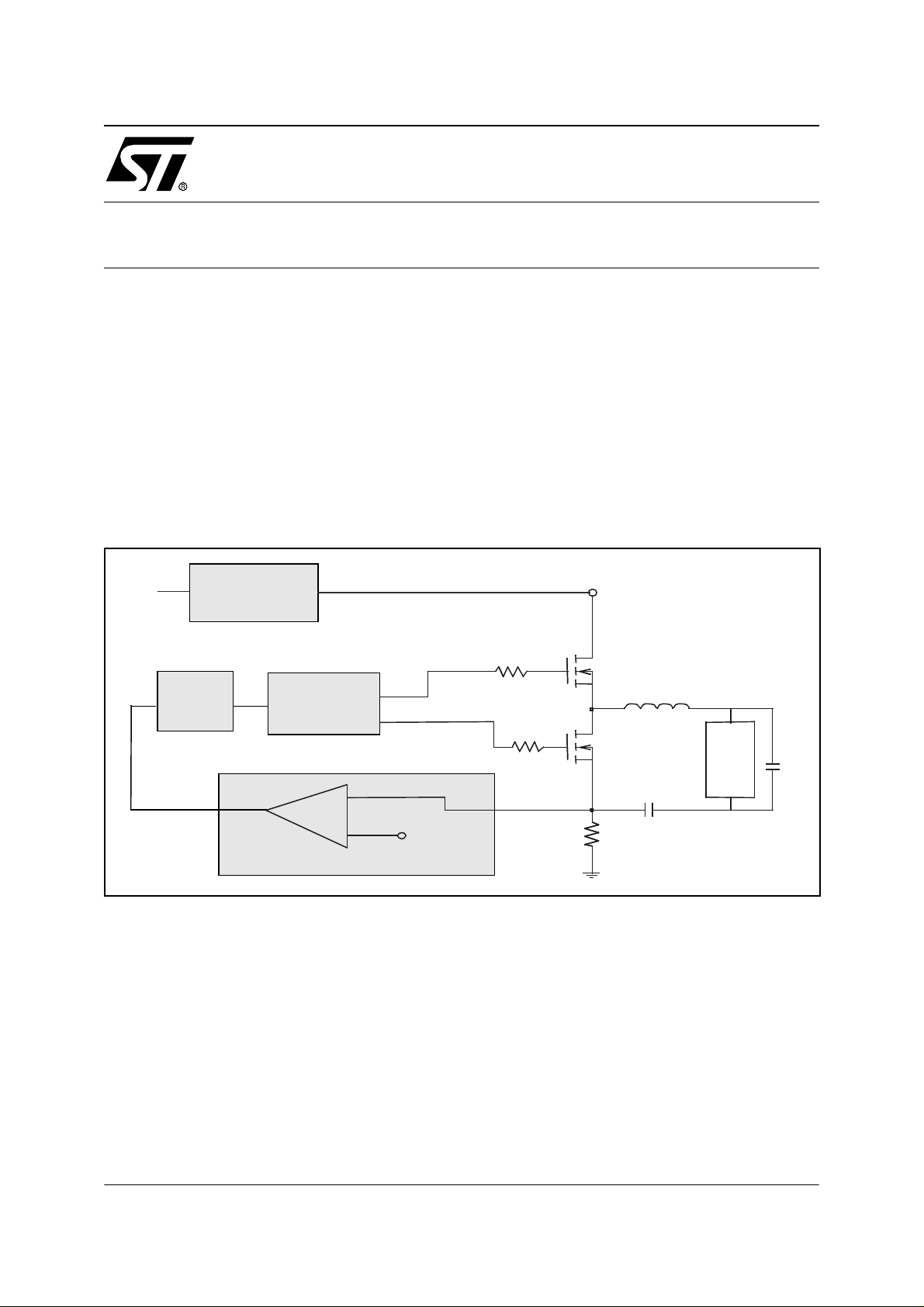
First, lets look at a basic diagram of an existing electronic ballast.
LINE
INPUT
POWER FACTOR
CONTROLLER
VCO
CONTROL
HALF BRIDGE
DRIVER
Ref.
450 V
Lres
DC BLOCK
LAMP
Cres
This is a v ery simp le di agram of an ex isting el ectroni c ba llast. To day, the volt age co ntrol led
oscillator (VCO) and the half bridge driver are usually combined in a single package. The Control portion, which may be comprised of the fault detection circuitry and an op-amp to close the
loop, may also be includ ed in the sam e package (for examp le, the L657 4 Ballas t Control ler
IC). This is a good solution for having a basic platform from which new designs can easily be
made. In some c ases, it ma y b e necess ary to i nclude a m ore flexible solution tha t allows for
parameters that are usually fixed in an analog s olution – such as i gnition profiles and restart
methods. It is in the se an d many othe r c ase s tha t a m icroc ontroll er can be us ed to de fine a
more user specific operating profile.
AN1501/0202 1/13
1
Page 2
SIMPLE MICROCONTROLLED BALLAST
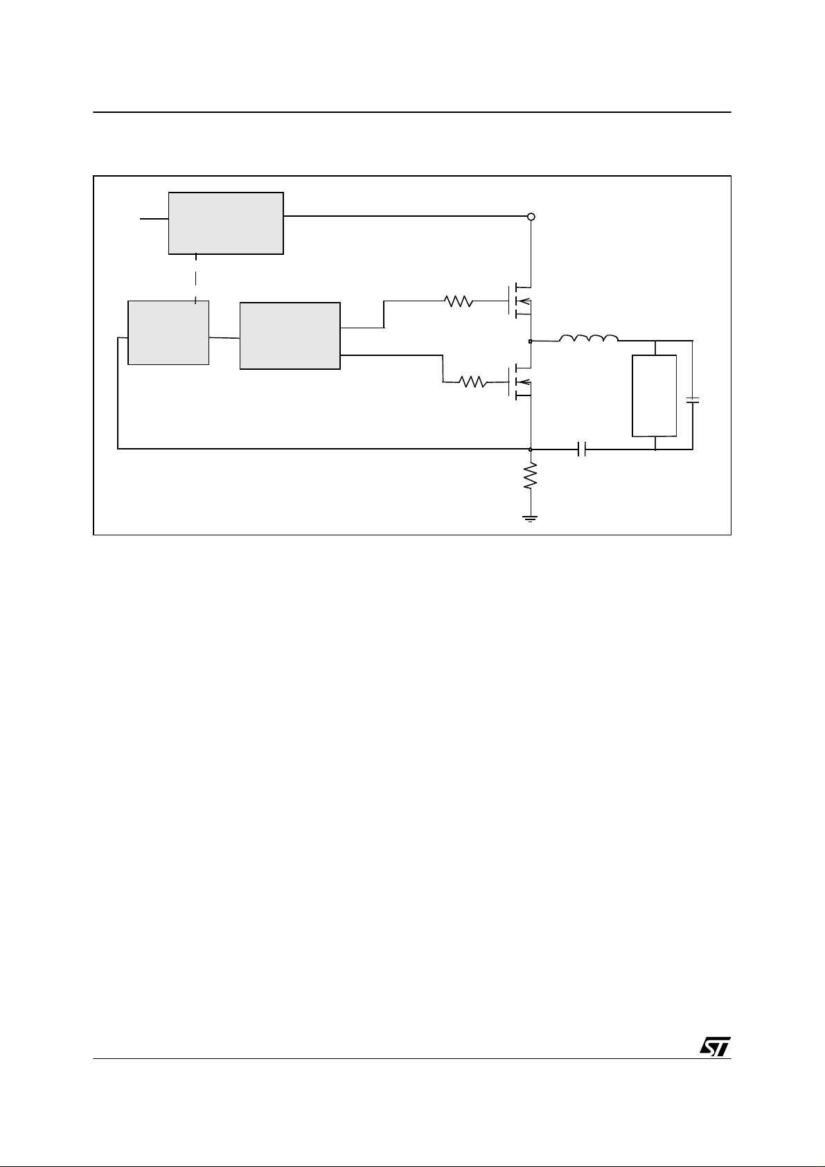
A simplified diagram of a microcontrolled ballast is shown below.
LINE
INPUT
POWER FACTOR
CONTROLLER
MICRO
HALF BRIDGE
DRIVER
450 V
Lres
DC-BLOCK
LAMP
Cres
In this diagram, the microcontroller takes the place of the VCO and the control logic. The microcontroller has an output(s) that emulates the VCO output which in turn controls the turn-on
and turn-off the upper and lower portion of the half bridge. In this manner, the dead time, frequency, and duty cycle of the half bridge output can all be independently controlled.
The control log ic that has be en re placed by t he micro is esse ntially th e b rains o f t he cont rol
logic. External analog components will still be needed to scale down and, if needed, filter the
fault signals. The micro can then control the response to each fault condition as determined by
the users programming code. An example of when this might be useful is when a lamp fails to
ignite, the micro could detect this and restart the preheat and ignition sequence but with a
longer preheat time.
2/13
2
Page 3
SIMPLE MICROCONTROLLED BALLAST
1 MICROCONTROLLER FUNDAMENTALS
To understand how the micro can be used in a ballast, the basic components that will generally be used need t o first be unders tood. One of th e few basic comp onents that will be used
are “inputs” and “outputs”. By this we mean that when the us er prog rams the micro, the programming code tells it which pins are t o be an input or an ou tput. N ot all pins ca n be c onfigured in this manner, but for now we will concentrate on the pins whose functions we can
modify.
First lets look at a pin that we have configured as an input pin. An input pin essentially looks
at the voltage on the pin and passes this information to the main processor (the “brain” of the
microcontroller). It can tell the processor when it sees a rising or falling voltage level, or it can
read the exact voltage level on that pin. Which ty pe of voltage it is to l ook for is something that
the user configures when the user programs the microcontroller. Generally, a pin that is configured as an “input” looks for either a high or low voltage level. An “analog input” is an input
that reads the exact voltage level on the pin as opposed to looking only for a high or low level.
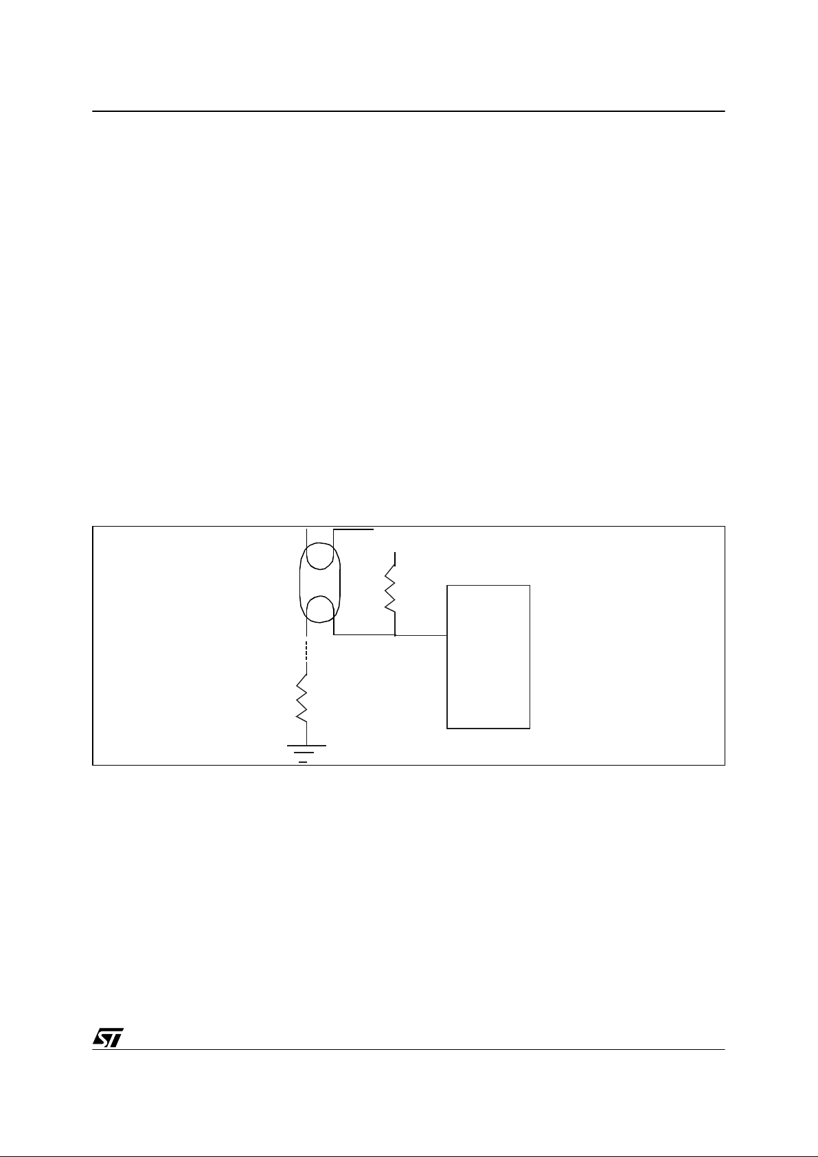
A typical example using an “input” pin is shown below.
1.1 INPUT EXAMPLE
5V
10k ohm
Input
µ
1 ohm
In this example we configure the pin to be an i nput pin and to l ook for a high voltage. For instance, when the lower lamp filament is connected to the 1 ohm resistor, the 10k ohm and 1
ohm resistor form a voltage divider where the midpoint is brought to the input pin. When the filament is connected to the 1ohm resistor, the voltage divider applies approximately 0 volts to
the input pin. When t he f ilament is disconnec ted from the 1 o hm res istor, for ins tance i n the
case of lamp removal (as shown in the picture), the vol tage on the input pin rises to 5v. The microcontroller sees this voltage level shift, and can then take the appropriate ac tion. The action
taken is dete rmined by what the user tells the micro to do when the microcontroller is programmed. In this case the user may tell the ballast to turn off since the lamp has been removed.
C
3/13
Page 4

SIMPLE MICROCONTROLLED BALLAST
1.2 ANALOG INPUT EXAMPLE
5V
Analog Input
µ
C
HALF BRIDGE
+HV
Q1
Q2
L
C
When a pin is configured as an “analog input” it acts as an A/D converter and looks at the
voltage on the pin and transforms that voltage of 0V to 5V into a corresponding number between 0 and 255. For example, if the voltage on the Analog Input pin is 2.5 V, then the A/D will
convert the 2.5V to a value of 128. The program that has been stored i n the m icro may then in
turn tell an output pin to change the frequency of the half br idge to that of a 50% dimming level.
How does the mi crocontr oller change th e freque ncy of the half br idge? This i s done by controlling a pin that has been configured as an “Output” pin.
Just as we configured a pin to be either an “input” or an “analog input”, we can also configure
a pin to be used as an “output”. An output pin can configured in two different states – either a
“push-pull” output or an “open drain” output.
In the push-pull configuration, a “high” can be applied to the pin. This puts a voltage on the pin
that is equ ivalent to the V cc of th e microc ontro ller wi th a limit ed curre nt sour cing capabi lity
(few mA). The second mode in the push-pull configuration is a “low”. In the low state, the pin
is shorted to ground and again has a limited capability to sink current up to 30mA (high current
pins only). An example of a “push-pull” configuration is given next.
4/13
Page 5

1.3 PUSH-PULL OUTP UT EXAMPLE
SIMPLE MICROCONTROLLED BALLAST
+HV
Output
5v
HALF
BRIDGE
5V
Q1
0V
Input
Q2
Q1
Q2
µc
In this example, the pin is configured as a push-pull output. The output pin goes from a “low”
to a “hig h” sta te, whic h in tu rn a ppl ies 0V o n the ou tput pin an d then 5 V co rresp onding ly. A
“low” on the pin is accomplished by turning on the lower FET in the µC, thus pulling the output
pin to ground. A “high” is accomplished by turning off the lower FET and turning on the upper
FET in the microcontroller.
In the example above, a single output from the micro goes into a single input on a half bridge
driver. In cases where the user wants to control the upper and lower FET independently, a half
bridge driver with two inputs can be used – one for turning on/off the upper FET and another
for turning on/off the lower FET. In that case, the user would configure two pins on the microcontroller as outputs – one for each half bridge input. An example of when this would be useful
is when the user wa nts t o dim the ballast by var ying t he PWM duty cy cle o f the hal f bridge
output instead of only varying the frequency as shown above.
The second configuration of the output pin is as an “open drain” output. This configuration is
general ly char acte rized as an open d rain F ET. In this cas e a “hi gh” c orres pond s to the pin
being in a “float ing” stat e and a “lo w” again acting as a short to gr ound . An exam ple of thi s
state being used would be when the user wants to short a point to ground, but at all other
times, the pin is to have no affect on the circuit.
In addition to the aforementioned parts of a micro, there are many other components that can
be used in a ballast. We will discuss the most common components briefly and leave it to the
reader to further investigate each components workings in more detail.
5/13
Page 6

SIMPLE MICROCONTROLLED BALLAST
2 AUTORELOAD TIMER
The first component (or peripheral) i s called the “ autoreload timer“. The autoreload timer is just
what its name implies. It is a timer that the user sets up in his/her program that automatically
restarts after it has timed out. The user will specify how long the timer is to count for and in addition, can also have actions taken at the beginning and at any point within the count. If for instance the user had an operation that was to operate continuously with respect to time, there
would be little sense in having the program repeat lines of code continuously. This is because
the microprocessor core (brain) has to operate on each line of code as it runs through the program. Thus in an operation such as the push-pull output example above, each time the output
is to switch from high to low and visa versa, the processor would have to process the instructions for each change. However, w ith the autorelo ad timer, we can tell the tim er to mak e the
output go high at the beginning of each count and somewhere before the count runs out, we
tell the timer to make the output go low. An example diagram of this function is shown below.
COUNTER
RELOAD
255
000
t
t
VR001852
COMPARE
VALUE
REGISTER
PWM OUTPUT
Notice in the diagram above there is a starting point c alled the reloa d register. This is where
the count begins and the output goes high. The second point is the compare value. Once the
counter reaches this value output goes low. So, by adjusting the reload register value the frequency of the PWM output is set. By adjusting the compare value, the duty cycle is then set.
In most cases if th e au toreload ti mer i s bei ng used to drive th e P WM f or the half br idge, the
duty cycle will most likely be 50%. So in that case the compare value would be set half way between the reload register value and the value 255.
In summary, the autoreload timer can be set up once to operate by itself s o that the pr ocessor
core can perform other functions. If the frequency needs to be changed, the program can
again load new values into the reload register and compare value, and start the counter agai n
6/13
Page 7

SIMPLE MICROCONTROLLED BALLAST
running on its own. The autoreload timer also has other functions, but this is probably one of
the most common usages in ballast design. A brief look at a datasheet of one of ST ’s microcontrollers with the autoreload featur e wi ll go i nto more detail on the capabil it ies of this peripheral.
3 TIMER
In addition to the autoreload timer, there may also be more than one generic timer available.
The generic timer counts down to zero from a number that is input from the user program. The
duration of each count can also be modified by loading a different number into it’s corresponding register. An example of when the timer could be used would be the following. In
order to preheat the lamp filaments of a microcontrolled ballast, the autoreload timer could be
set to output a PWM (as discussed above) at 100 kHz. Once the PWM was started, the timer
could be set up and turned on to count for 1 second. After the timer finished counting, the
counter would tell the processor it was finished and the user program could then tell the autoreload timer to operate at a different frequency or ramp down to an ignition frequency. This
process will be detailed once we look at the example program (later in the paper).
4 PROGRAM MING AND OPERATION
Now that we have some of the basic components of the microcontroller covered, lets discuss
a few more details and then show how this is all implemented in an example program.
First, lets discuss how the microcontroller operates. It is assumed that the user has had some
programming experience. When the user writes a program, that program is stored in the
memory of the m icroco ntroller. The pr ocessor then starts from the begin ning of t he program
and works its way down pe rform ing ope ratio ns that th e progra m te lls it to do ( such as configure pin one as an output, then make it a “high” etc.) from the beginning to the end of the program. Programs must never end and should always run in some type of continuous loop.
One main feature that a program performs is to look for signals that require som e type of action to be taken. This was shown in the first example. When the input went fr om 0 to 5V, the
processor is to shut down the ballast. They way in which the processor knows that the voltage
has changed can be determined in two w ays – either by polling or by an interrupt. W hen we
poll an input, we essentially write in code into our program to go and look at the input pin to see
if its voltage level has changed. If this voltage change is a critical parameter, code must be entered quite often to go and look at this pin. One problem with this method of detection is that it
the processor must stop what it is doing, go look at the pin, and go back to what it was doing.
However, if a critical fault occurs, damage may be done before the code gets back to the point
where it looks for that fault. In that case it may be best to use the second method of detection
– an interrupt.
7/13
Page 8

SIMPLE MICROCONTROLLED BALLAST
When time is of the essence to capture a fault signal, an interrupt may be used to tell the micro
that a problem has occurred. An interrupt i s a s ignal that i s sent to the pr ocessor to essentially
“interrupt” what it is currently doing and take care of the issue that caused the interrupt. Many
of the pins that are configured as inputs can also be configured to generate an interrupt. With
an interrupt enabled pin, the program code does not have to be written to constantly go back
and look at the voltage on the pin. The microcon troller is able to watc h the pin for changes,
while at the same time running the program code that i s performing other operations. Relating
again to our first example, if the lamp is removed and the ballast is not shut down immediately,
hard switching could occur and damage to the circuit could result. In this cas e the user could
program the input pin to trigger an interrupt when the fault occurs. The interrupt would then tell
the micro where to go in the code to take care of the problem.
So what method should be chosen to detect changes in a pins voltage level or state? This is
dependa nt on how criti cal the t iming is. If it is not crit ical, th e use r may wa nt to p oll th e pin
since this is always available (simply adding addi tional code). The main reason that one would
not always want to use an interrupt is two-fold. First, depending on the type of interrupt that is
being used, a more critical interrupt may happen on another pin. If this happens, the more critical interrupt may not be taken care of until the first interrupt is resolved. Second, not all pins
can be enabled with an interrupt that will operate in the same fashion. For instance, some pins
will only a llow a rising ed ge interru pt, and i f all of thos e in terrupts are t aken with on ly fa lling
edge interrupts available, then the u ser mi ght have to p ut an inverting ci rcuit into th e proje ct
(thus more co st). Ot her reas ons a nd options will be com e mo re ap parent as the us er be gins
programming.
8/13
Page 9
SIMPLE MICROCONTROLLED BALLAST
5 STORING DATA
Another advantage of using a micro is the ability to store information. This information can
take many forms. One type of information that can be stored is data that may be used depending on what inputs the micro receives. For instance, if the circuit detects that a 18W CFL
is inserted into the lamp socket, a different preheat time may be desired than would be used
for a 13W CFL. The microcontroller’s “analog input” will take the input from the lamp detection
circuit, ma tc h it wi th t he co rrec t pr eh eat t im e, an d lo ad th at tim e into t he “ time r”. I f the 1 3W
CFL was inserted, the sa me process w ould occur, but the timer would pick the othe r stored
time variable and load it into the “timer” instead.
If the amount of data that needs to be retrieved is larger than just a few points of data, a “table”
may be used. A tab le is an area of me m ory where larger am ounts of dat a can be s tored. An
example of when a tabl e might be us ed is for the definition of a dimm ing level . Lets sa y that
one of the microcontrollers inputs monitors a voltage level (0-5V for instance). A voltage of 0V
corresponds to a dim level of 1%, 2.5V equals 50%, and a voltage level of 5V corresponds to
a dim level of 100%. The PWM frequency that corresponds to each of the dim levels is 90kHz,
65kHz, and 55kHz correspondingly. Thus a representative table may look like this for a typical
dimming design:
A/D reading Corresp onding dim level PWM freque n c y
0V 1% 90kHz
1V 20% 80kHz
2V 40% 70kHz
3V 60% 60kHz
4V 80% 58kHz
5V 100% 55kHz
The actual data table (s) would stor e the appropriate va riables to mak e the autoreload timer
operate at the frequencies s hown in the chart. A lso, if a more detailed dimming range i s
needed, the table would be enlarged to include A/D readings that had fractional voltages. For
example, 1.1V may correspond to a dim level of 21% - etc.
9/13
Page 10

SIMPLE MICROCONTROLLED BALLAST
Figure 1. Simple microcontrolled b a llast schematic
120v AC
POWER
SUPPLY
VIPer Demo
12v Out
R13
5v
C10
FAULT DETECTION
C8
STP5NB60
D3
C7
V1
D2
C6
0
0
C4
HALF
BRIDGE
U4A
M1
R6
1n
8
BS
IN
1
12v
L1
7
243
6
HVG
Vs
C3
M2
R7
OUT
DT
5
R3 R10
C9
LVG
GND
STP5NB60
L6384
0
R11
R14
R12
D4
R9C5
5v
D1
0
R15
0
C11
0
FAULT
0
R8
0
0
FAULT DETECTION
DETECTION
10/13
12v
POWER
SUPPLY
0
C2
16
15
NMI
RST
PC3/AIN
PC2/SIN/AIN
PB0
Vpp/TEST
PB2
1
3
GND
PB3
4
0
U2
1
2
MICRO
CONTROL
L493150
U5
INOUT
23
X1
8MHz
11
12
OSCIN
OSCout
ARTIN/PB6
ARTOUT/PB7
5
6
5v
91410
PA4/AIN
PA5/AIN
Vss
VDD
8137
R1
C1
ST62T52CB3
0
0
R2
0
Page 11

SIMPLE MICROCONTROLLED BALLAST
6 EXAMPLE PROGRAM
We will now look at an exam ple program written in assembly language just to gi ve an idea of
what the code might look like. We will point out the major sections of the code and what they
are doing. It is also written in C language as well and is i ncluded after the as sembly language.
The associated zip file is the code (written in “C” & assembly) used for the demonstration ballast. Programm ing com ments are inclu ded to help user s and other pr ogrammer s determi ne
what is happening in the main parts of the code.
In addition, in the appendix section, you will find the flowchart of the program.
11/13
Page 12

SIMPLE MICROCONTROLLED BALLAST
APPENDI X
Figure 2. Flowchart
Start
Load
Watchdog
Initialize
Variables
Load
Watchdog
Check Lamp
for
Open- Load
Open-Load?
No
Check Lamp
for
Over-Voltage
Over-Voltage?
No
Yes
Yes
Check Lamp
for
Open- Load
Yes
Open-Load?
No
Check Lamp
for
Over-Voltage
Yes
Over-Voltage?
No
12/13
Configure
Ports
Load
Watchdog
Setup Auto
Reload Timer
Set Lamp
Preheat
Start Lamp
Ignition
Sequence
Set Lamp
Operating
Frequency
Monitor Zero
to Ten
Volt Reference
Set Dim Level
from zero to ten
volt reference
Page 13

SIMPLE MICROCONTROLLED BALLAST
“THE PRESENT NOTE WHICH IS FOR GUIDANCE ONLY AIMS AT PROVIDING CUSTOMERS WITH INFORMATION
REGARDING THE IR PRO DUCT S IN OR DER FO R THEM TO SAV E TIME . AS A RES ULT, STMIC ROEL ECTR ONI CS
SHALL NOT BE HELD LIABLE FOR ANY DIRECT, INDIRECT OR CONSEQUENTIAL DAMAGES WITH RESPECT TO
ANY CL AIM S AR IS IN G FR OM T HE CO N TENT OF S UC H A NO TE A ND /O R T HE U SE M AD E BY C US TO ME RS O F
THE INFORMATION CONTAINED HEREIN IN CONNEXION WITH THEIR PRODUCTS.”
Information furnished is believed to be accurate and reliable. However, STMicroelectronics assumes no responsibility for the consequences
of use of such information nor for any infringement of patents or other rights of third parties which may result from its use. No license is granted
by implic ation or otherwise under any patent or p atent rights of STMi croelectroni cs. Specifications mentioned in thi s publicati on are subject
to change without notice. This publication supersedes and replaces all information previously supplied. STMicroelectronics products are not
authorized for use as cri tical comp onents in life support dev i ces or systems wi t hout the exp ress written approval of STM i croelectronics.
The ST logo is a registered trademark of STMicroelectronics
2002 STMicroelectronics - All Rights Reserved.
STMicroelectronics Group of Compan i es
http://www.s t. com
Purchase of I
2
C Components by STMicroelectronics conveys a license under the Philips I2C Patent. Rights to use the se components in an
2
I
C system i s granted pro vided that th e sy stem confo rm s to the I2C Standard Specification as defined by Philips.
Australi a - B razil - Canada - China - Finl and - France - Germany - Hong Kong - Ind i a - Is rael - Ital y - J apan
Malaysi a - M al ta - Morocco - Singapore - Spain - Sw eden - Switz erland - Unit ed Kingdom - U.S.A.
13/13
 Loading...