

Page 1
AN1499
APPLICATION NOTE
DESIGNING A LOW COST POWER BOARD FOR THE
ST92141 MOTOR CONTROL MCU WITHOUT USING IPMs
By Motor Control Competence Center
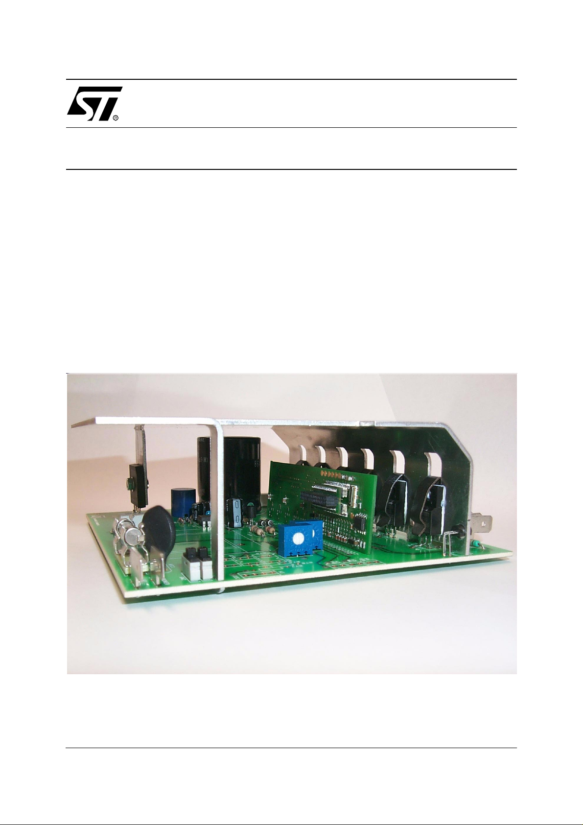
INTRODUCTION
Power Modules ha ve been i n use for t wenty year s in industr ial m otor drive a pplicati ons. F or
power stage designs, they give the advantages of compactness and good thermal behavior.
Over the last few years a new family of Power Modules, called Intelligent Power Modules
(IPM), have tried to take the integration of motor drive power stages a step further.
These IPMs target lower power and lower cost motor drive system s compared to those targeted by standard Power Modules.
However it is an open question whether these IPMs suit high volume and very co st-sensitive
applications, such as the household appliance market.
Figure 1. General System View
AN1499/0202 1/21
1
Page 2

Table of Contents
INTRODUCTION . . . . . . . . . . . . . . . . . . . . . . . . . . . . . . . . . . . . . . . . . . . . . . . . . . . . . . . 1
1 INTELLIGENT POWER MODUL ES . . . . . . . . . . . . . . . . . . . . . . . . . . . . . . . . . . . . . . . 3
1.1 ADVANTAGES OF IPMS . . . . . . . . . . . . . . . . . . . . . . . . . . . . . . . . . . . . . . . . . . . 3
1.1.1 Assembly cost . . . . . . . . . . . . . . . . . . . . . . . . . . . . . . . . . . . . . . . . . . . . . . . . . . . . . . 3
1.1.2 Co mpo nent coun t . . . . . . . . . . . . . . . . . . . . . . . . . . . . . . . . . . . . . . . . . . . . . . . . . . . . 3
1.1.3 Reduction i n time to market . . . . . . . . . . . . . . . . . . . . . . . . . . . . . . . . . . . . . . . . . . . . 3
1.1.4 Higher reliabi lity . . . . . . . . . . . . . . . . . . . . . . . . . . . . . . . . . . . . . . . . . . . . . . . . . . . . . 4
1.1.5 Product compactness . . . . . . . . . . . . . . . . . . . . . . . . . . . . . . . . . . . . . . . . . . . . . . . . 4
1.1.6 Package ind uc tance . . . . . . . . . . . . . . . . . . . . . . . . . . . . . . . . . . . . . . . . . . . . . . . . . . 4
1.2 DRAWBACKS OF IPMS . . . . . . . . . . . . . . . . . . . . . . . . . . . . . . . . . . . . . . . . . . . 5
1.2.1 Lead fram e . . . . . . . . . . . . . . . . . . . . . . . . . . . . . . . . . . . . . . . . . . . . . . . . . . . . . . . . . 5
1.2.2 He atsink planarity and stiffness . . . . . . . . . . . . . . . . . . . . . . . . . . . . . . . . . . . . . . . . . 5
1.2.3 Embedded gate drive & filter cost . . . . . . . . . . . . . . . . . . . . . . . . . . . . . . . . . . . . . . . 5
1.2.4 Ext ernal bootstrap diodes and temperature pro tection neede d . . . . . . . . . . . . . . . . . 5
1.2.5 Co mpo nent choice . . . . . . . . . . . . . . . . . . . . . . . . . . . . . . . . . . . . . . . . . . . . . . . . . . . 5
2 AN ALTERNATIVE SOLUTION . . . . . . . . . . . . . . . . . . . . . . . . . . . . . . . . . . . . . . . . . . 6
2.1 ADVANTAGES . . . . . . . . . . . . . . . . . . . . . . . . . . . . . . . . . . . . . . . . . . . . . . . . . . . 6
2.1.1 Assem bly & m ounting cons iderations . . . . . . . . . . . . . . . . . . . . . . . . . . . . . . . . . . . . 6
2.1.2 Reduction i n time to market . . . . . . . . . . . . . . . . . . . . . . . . . . . . . . . . . . . . . . . . . . . . 6
2.1.3 Reliability considerations . . . . . . . . . . . . . . . . . . . . . . . . . . . . . . . . . . . . . . . . . . . . . . 7
2.1.4 Therm al management . . . . . . . . . . . . . . . . . . . . . . . . . . . . . . . . . . . . . . . . . . . . . . . . 7
2.1.5 Gate drive optimization . . . . . . . . . . . . . . . . . . . . . . . . . . . . . . . . . . . . . . . . . . . . . . . 7
2.2 DRAWBACKS . . . . . . . . . . . . . . . . . . . . . . . . . . . . . . . . . . . . . . . . . . . . . . . . . . . 7
2.2.1 Co mpo nent coun t . . . . . . . . . . . . . . . . . . . . . . . . . . . . . . . . . . . . . . . . . . . . . . . . . . . . 7
2.2.2 PCB connec tions . . . . . . . . . . . . . . . . . . . . . . . . . . . . . . . . . . . . . . . . . . . . . . . . . . . . 7
3 CONCLUSION . . . . . . . . . . . . . . . . . . . . . . . . . . . . . . . . . . . . . . . . . . . . . . . . . . . . . . . 8
4 MECHANICAL DATA: ST92141-PLATFO RM . . . . . . . . . . . . . . . . . . . . . . . . . . . . . . 19
5 CONTROL BOARD LAYOUT (ORCAD FILES AVAILABLE) . . . . . . . . . . . . . . . . . . 20
2/21
1
21
Page 3

DESIGNING A LOW COST POWER BOARD FOR ST92141 MOTOR CONTROL MCU ...
1 INTELLIGENT POWER MODULES
These products integrate in a single transfer molded package, six IGBTs, six free wheeling diodes and the interfacing circuits needed to enable direct control from a microcontroller.
In their low cost version they do not include the front-end rectification diodes, nor do they have
a switch or diode for active power factor correction.
External circuits are still needed, such as bootstrap supplies, current sensing and filtering, and
auxiliary supply decoupling.
This applic ation n ote a naly zes the a dvant age s an d d raw back s o f this p ower in tegr ation ap proach with regard to the constraints of cost sensitive motor drives.
An alternative solution is proposed that fits better to appliance and large volume applications
in term of optimization and cost.
1.1 ADVANTAGES OF IPMS
Out of all the advantages that are claimed, the major ones seem to be the following:
– Less assembly cost
– Lower component count
– Reduction in time to market
– Higher reliability
– Product compactness
– Low inductance package
These are general claims that need to be confronted with reality.
1.1.1 Assembly cost
Assembling an IPM requires placing it on the PCB, wave soldering and later on fixing the heatsink with s crew s. Th ese o perat ions ar e inde ed less exp ensive th an ass embli ng six d iscre te
components. You should note how ever that if an active power fac tor corrector is needed, external discrete power components are required.
1.1.2 Component count
This is a clear advantage because nine components are replaced by each IPM. However the
need for microcontroller and passive component assembly remains and IPMs do not r em o ve
any major manufacturing step.
1.1.3 Reduction in time to market
Layout of IGBT and MO SFET gate drives requires special expertise. U sing an IPM does not
require all this expertise, but a good understanding of EMI and parasitic inductance effects is
still strongly recommended!
3/21
2
Page 4
DESIGNING A LOW COST POWER BOARD F OR ST92141 MOTOR CONTROL MC U ...
Assuming this expertise is available, the estimated saving will be hardly be more than the time
it takes to have a coffee break!
1.1.4 Higher reliability
From a silicon point of view , there are still about 1 5 dice inside the modu le with th eir own
MTBFs rela ted to j unction te mpe rature as well as m ore than 40 wire bo nds. So th e syst em
MTBF may increase because the connection and assembly count decreases. However it may
decrease if the heatsink is not perfectly flat below the whole IPM surface.
1.1.5 Product compactness
When just com paring power switches, IP Ms br ing c omp actnes s. But when ta lking ab out the
whole system, the difference i s negligible. Passive c omponents , heatsink, PCB and c onnectors are by far the most bulky parts.
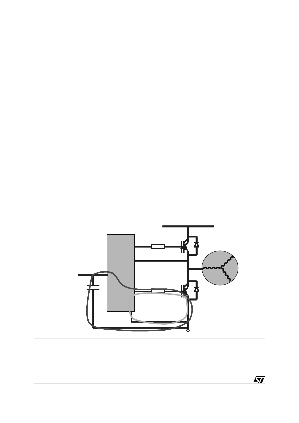
1.1.6 Package inductance
The only circuit area where IPMs reduce the parasitic inductance is located between the gate
drivers and the pow er sw itches. T his is true for the h igh side g ate dri vers but not f or the low
side drivers.
Figure 2 shows that during turn-on, the low side gate drive current loop (B) is not internal to the
module but goes outside. In this case, IPMs do not have a significant advantage over discrete
solutions.
Figure 2. Low side gate drive current loop
Half
Bridge
driver
Vcc
A
B
4/21
Page 5

DESIGNING A LOW COST POWER BOARD FOR ST92141 MOTOR CONTROL MCU ...
1.2 DRAWBACKS OF IPMS
Counterbalancing the advant ages listed above , IPMs have m ajor draw backs that m ake their
use in cost sensitive applications rather questionable.
Let’s review these drawbacks:
1.2.1 Lead frame
Due to manufacturing constraints, an IPM has leads on both sides of the pac kage. This means
that the PCB must be installed parallel to the pack age. So the heatsink must have its contact
base parallel to th e IPM and th e PCB. Whe n you are lo oking for a v ery cheap so lution, this
makes the choice of heatsink difficult.
1.2.2 Heatsink planarity and stiffness
Inside the IPM, power switches are soldered directly on a long and thin lead frame. Then this
lead frame is fully molded for isolation between the heatsink and the active parts. As a result,
these IPMs have a low stiffness and need to be assembled on a good quality heatsink to avoid
internal cracks. As a consequence, cheap heatsinks made of metal sheet are not recommended. This may lead to additional cost.
1.2.3 Embedded gate drive & filter cost
One sensitive parameter, in terms of optimizing the motor drive cost, is gate drive impedance.
By adjusting this imped anc e properly, you can find th e ri ght c ompr omis e b etwee n f ilter cos t
and heatsink cost. As IPMs do not give access to the gate drive impedance, you cannot adjust
the dV/dt commutation which may lead to additional filter cost.
1.2.4 External bootstrap diodes and temperature protection needed
Most IPMs available today do not hav e over-temperature protec tion. This requires additional
external circuits.
As bootstrap diodes are not integrated in the module, they need to be added externally. This
leads to additional cost.
1.2.5 Component choice
Needless to say the choice of IPMs today is very scarce and does not match the broad range
of power switch and interface circuits. This is a real drawback when cost is all-important.
5/21
Page 6

DESIGNING A LOW COST POWER BOARD F OR ST92141 MOTOR CONTROL MC U ...
2 AN ALTERNATIVE SOLUTION
The basic idea behind the IPM solution consists of reducing the component count, simplifying
assembly and making board layout easier. However it has been shown that the cost benefit is
not always easy to determine when you calculate at system level.
Another way to split the system consists of grouping all the system SMD components on a
small size FR4 board, called the Control Board, and keeping all the power sw itches and discrete components on a mother board called the Power Board.
Figure 5, Figure 6 & Figure 7 show an AC motor drive application using this partitioning. An ex -
ample layout and parts list are given in Appendix 2.
It is worthwhile to review the advantages and drawbacks of this new partitioning.
2.1 ADVANTAGES
2.1.1 Assembly & mounting considerations
Figure 6 shows a contr ol bo ard s chem atic im plem enting a m icrocon troller, i ts pe ripheral c ir-
cuits and three High Voltage Integrated Circuits for interfacing directly to the Power Board
schem atic show n in Figure 7. This microcontroller is dedicated to AC motor control and is
housed in a shrink SO34 package (refer to the parts list in Appendix 2 and ST92141 and
L6386 datasheet on http:\\www.st.com).
The size of this type of control board is about 26mm by 87mm. This makes use of available
FR4 hardware . This board can be plugged into the Power Boar d next t o the discrete power
switches. T he Power Board layout is very easy and simple, even if low cost materials like
CEM1 are used. This makes the size of the Power Board smaller even if single side copper is
used.
The total volume of the Control Board and the power switches is very compact.
Moreover, the discrete Power switches can fit many different heatsink configurations, parallel
or perpendicular, with no planarity and stiffness constraints.
Another ad vantag e co mes f rom the s olderi ng proces s d ifferen ti ation: SM D com pon ents are
soldered using a reflow process, discrete components go through solder waves. This improves the production yield.
Finally, if an active power factor is needed, it is easy to add another switch to the power stage.
2.1.2 Reduction in time to market
The physical spli t between co ntrol circuits and power parts make the system easy to layo ut
and quick to debug. T he system power r ange or the input front end can be adapted w ithout affecting the Control Board and v ice versa. Any change of microcontroll er package or i ts peripheral circuits does not interfere with the power stage.
6/21
Page 7

DESIGNING A LOW COST POWER BOARD FOR ST92141 MOTOR CONTROL MCU ...
In other words, the same Control Board can fit different Power Boards.
This makes the first design shorter and the future re-design even faster.
2.1.3 Reliability considerations
The reflo w proces s u s ed to sold er the Co nt rol B oa rd is prov en to be m ore rel iable t han the
wave process.
The connection between both boards is done during the wave process. Figure 5 shows a typical implementation and Appendix 1 gi ves the results of the v ibration test performed on this assembly.
2.1.4 Thermal management
Assembling the d iscr ete comp onen ts b y c lips e nab les the d issip ation to b e spre ad ov er t he
whole heatsink surface. This avoids concentrating the losses on a small ar ea and allows you
to use cheap heatsink technology made of metal sheet.
2.1.5 Gate drive optimization
Figure 8 shows the influence of the gate drive impedance on the conducted noise. As the
whole gate drive is available on the Control Board, it is easy to adapt the noise level according
to the filter attenuation at any time. This noise level optimization can save time and cost.
Moreover the Control Board design allows t he use of ad vanced High Voltage Integrated Circuits that integrate a bootstrap diode and comparators (refer to L6386 on http:\\www.st.com).
The is true for power switch selection (see the fully insulated TO220 products like
STGP7NB60HDFP on http:\\www.st.com).
2.2 DRAWBACKS
The main drawbacks relate to:
2.2.1 Component count
Compared to the IPM solution, both the Control Board and the Power Board each implement
about six components more.
2.2.2 PCB connections
The double sided Control Board soldering totals 68 contacts that are processed during wave
soldering.
7/21
Page 8

DESIGNING A LOW COST POWER BOARD F OR ST92141 MOTOR CONTROL MC U ...
3 CONCLUS ION
This comparison between two different system partitioning methods has shown that the Intelligent Module approach is not the most flexible and cheap solution when designing c ost sensitive motor control applications.
The alternative solution that is presented gives several advantages that are decisive when
cost is the overriding factor:
– Access to low cost heatsink technology and better thermal management
– Use of different processes for SMD and through-hole components to improve the production
yield
– Fexibility to adapt the Power Board with no impact on the Control Board and vice versa
– Access to gate drive impedance to optimize the EMI level at any time
– Choice of a large portfolio of interface ICs and power switches
For further details about the Control Board hardware and software features, refer to AN1498.
Figure 3. Control Board high voltage in ter facing side
8/21
Page 9

DESIGNING A LOW COST POWER BOARD FOR ST92141 MOTOR CONTROL MCU ...
Figure 4. Control Board microcontroller side
Figure 5. Control Board plugged into the Power Board next to the discrete parts
9/21
Page 10

DESIGNING A LOW COST POWER BOARD F OR ST92141 MOTOR CONTROL MC U ...
Figure 6. Typical Control Board circuit for AC motor control applications
+15V
C46
100nF
84
IC5A
+5V
7$&+20(7(5
J4
J6
C2
100nF
J10
J11
J13
J15
J16
J19
J20
J22
J24
J25
J27
J28
J34
R10
100K
C11
C10
10nF
10nF
R19
100K
R28
R29
100K
100K
C24
C23
10nF
10nF
R38
100K
100K
R1
10K
BAS16
10nF
R39
C25
D1
R4
10K
D2
BAS16
+5V
R2
10K
Q7
BC817-25
C3
100nF
+5V
R11
R12
100K
100K
C13
C12
10nF
10nF
R20
R21
100K
100K
+5V
R31
R30
100K
100K
C26
C27
10nF
10nF
R41
R40
100K
100K
+5V
R6
1
100R
R13
100K
C14
47pF
R22
100K
R32
100K
10nF
R42
100K
S
2
Q
3
W
4
VSS
R14
100K
R23
100K
R33
100K
R34
100K
C29
C28
10nF
R43
R44
100K
100K
TP8
C38
1uF
6&+(0$&$57(67(1*
Rq: All footprint components are 0603 packages except when noticed
U2
M95040
DATA
+5V
100nF
BAS16
HOLD
R45
220R
VCC
C33
D3
CK
1M
1
LM358D
8
7
6
5
C31
10nF
R49
U1A
+5V
C39
100nF
+5V
1
VDD
2
P3.0/MOSI
3
P3.1/MISO
4
P3.2/WKUP3/SCK
5
P3.3/SSN
6
P3.4/EXTRG/OCMPB
7
PS3.5/OCMPA/INT6
8
P3.6/ICAPA/WKUP2
9
NC
10
AVDD
11
AVSS
12
P5.7/AIN7/INTCLK
13
P5.6/AIN6/CK_AF
14
P5.5/AIN5
15
P5.4/AIN4
16
P5.3/AIN3/WDOUT
17
P5.2/AIN2/INT0/WDIN
+5V
84
3
+
2
-
R50
100K
R53
750R
1%
Rshunt
J1
LM358D
3
+
1
2
-
R52
33.2K
1%
C44
1uF
16V
C43
10nF
C15
470nF
TACHO
VPP_TEST
WKUP1/ICAPB/P5.0
WKUP0/NMI/P5.1
RESETN
OSCOUT
OSCIN
IC3
+5V
ST92T141K4M6
ST92141-Eng2
Rshunt
J33
C45
1nF
R54
47K
VSS
VH
VL
WH
WL
UH
UL
NC
VSS
VDD
C32
470nF
IC5B
LM358D
5
+
7
6
-
R56
1.5K
1%
R55
1.5K
D26
1%
BAS16
J3
J2
+5V
R17
10K
TP2
TP6
TP4
TP5
TP3
TP1
34
33
32
31
30
29
28
27
26
25
24
23
22
21
20
19
18
HSIC1
+5V
LSIC1
HSIC2
LSIC2
HSIC4
R35
LSIC4
100K
C21
470nF
XT1
CSTCC-MG 5MHz
(XT_CSTCCMG)
+5V
R63
390R
This drawing may not be reproduced to a third party unless permission is obtained in writing from ST MICROELECTRONICS
+15V
C5
470nF
25V
R18
1K
+15V
C16
C19
10nF
470nF
25V
TP7
+15V
C34
470nF
25V
C20
1nF
R26
2.7K
C35
1nF
R48
R80 6.8K
LSIC1
C6
1nF
LSIC2
HSIC2
LSIC4
HSIC4
HSIC1
2.2nF
820R
IC1 L6386D
1
2
3
4
5
6
7
R9
0R
1
2
3
4
5
6
7
C17
1
2
3
4
5
6
7
C36
1nF
1%
1%
C1
C40
470nF
470nF
16V
16V
14
LIN
VBOOT
SD
HVG
HIN
OUT
VCC
NC
DIAG
NC
CIN
LVG
GND
GND
IC2 L6386D
LIN
VBOOT
SD
HVG
HIN
OUT
VCC
NC
DIAG
NC
CIN
LVG
GND
GND
R27
1K
IC4 L6386D
LIN
VBOOT
SD
HVG
HIN
OUT
VCC
NC
DIAG
NC
CIN
LVG
GND
GND
R51
1%
4.7K
Title:
Organisation name: Approved by:
Size
Custom
Date: Sheet
D20
13
BAS16
12
11
10
9
8
D21
BAS16
C8
C41
470nF
470nF
16V
16V
14
13
12
11
10
9
8
14
13
12
11
10
9
8
D22
BAS16
D23
BAS16
C22
C42
470nF
470nF
16V
16V
D24
BAS16
R86
82R
67(1*
MCCC Rousset
Document Number Rev
<Doc>
34 pins connector
44 spaces used
1.905mm pin to
pin spacing
100pF
100pF
100pF
100pF
C4
100pF
C30
C37
100pF
220R
220R
C7
220R
C9
220R
C18
220R
220R
R5
R8
R16
R25
R37
R47
Drawn by:
BC807-25
Q1
remove 2 pins to
keep isolation
BC807-25
Q2
remove 2 pins to
keep isolation
BC807-25
Q3
remove 2 pins to
keep isolation
BC807-25
Q4
BC807-25
Q5
BC807-25
Q6
J-M RAVON
<OrgAddr2>
11Friday, November 16, 2001
of
board edge
remove 2 pins to
keep isolation
remove 2 pins to
keep isolation
R3
82R
R81
82R
R7
82R
R82
82R
R15
82R
R83
82R
R24
82R
R84
82R
R36
82R
R85
82R
R46
82R
D25
BAS16
J5
J7
J8
J9
J12
J14
J17
J18
J21
J23
J26
J29
J30
J31
J32
10/21
Page 11

DESIGNING A LOW COST POWER BOARD FOR ST92141 MOTOR CONTROL MCU ...
Figure 7. Typical Power Board circuit fo r A C m otor control applications
R73
0RWRU
3RZHU
,&
H3
1
2
3
4
H5
1
2
:DWHU/HYHO
33K
NTC1
4.7R
12
TP26
TP23
12
TP22
6SHHG5HIHUHQFH
43
43
TP9
R76
10K
J17
7DFKR0HWHU
J16
EI48
L3
23
D40
-+
4
1
STBR408
0.047R
+5V
J2
*
R75
4.7K
QRWPRXQWHG
12
43
IC8
SFH617A
J14
J13
TP25
TP24
J15
1
2
3
SW1
1K2
1
2
3
SW2
1K2
J8
H6
J11
AVDD
1
2
1
H7
This drawing may not be reproduced to a third party unless permission is obtained in writing from ST MICROELECTRONICS
R74
+5V
3RVLWLRQ6HQVRU
2
C70
220uF
385V
STTA106
D43
D41
D42
BZX55C15
C73
2.2uF
1 2
25V
C75
22nF
1N4148
J20
4
C72
9''
10uF
25V
0.23V
3
)%
t°
LM335Z
+
1 2
U2
S1
AVDD
'5$,1
SET
RES
6285&(
TP11
D44
STTA106
8
1
J6
X1
X2
567
IC6
VIPER12ADIP
1mH
2
GREEN LED
J3
Trimmer 50K
X3
X4
L2
D47
P1
TSL1112
R79
1.5K
J5
Trimmer 50K
+15V
BZX85C16
P2
J30
J4
J12
J9
J19
TP3
D46
12
1
C71
BZX85C5V1
25V
100uF
D45
1 2
J33
J34
J31
J32
J28
J29
J26
J27
J25
J23
J24
J21
J22
TP4
+5V
IC7
L78L05ACZ
3
Vin
Vout
GND
2
J1
STGP7NB60HDFP
T1
STGP7NB60HDFP
T2
2XTP15
STGP7NB60HDFP
T3
STGP7NB60HDFP
T4
STGP7NB60HDFP
T5
STGP7NB60HDFP
T6
:$6+(53/$7)250(1*
Title:
Organisation name:
Size
Document Number
<Doc>
Date: Sheet
J7
TP14
R72
0.047R
2W
MCCC Rousset
R70
1M
R71
12K
2XTP5
2XTP17
2XTP7
C74
47nF
400V
2XTP19
J18
Drawn by:
Approved by:
11Wednesday, November 21, 2001
H1
1
2
3
4
5
H2
1
2
2XTP10
2XTP2
F1
5A Slow
SUP FUSE 3527
TP27
R77
4.7K
29
'$7
IC9
SFH617A
&/.
9
R78
4.7K
SFH617A
IC10
J10
J-M RAVON
<OrgAddr2>
of
Rev
11/21
Page 12

DESIGNING A LOW COST POWER BOARD F OR ST92141 MOTOR CONTROL MC U ...
Figure 8. Conducted noise depending on gate drive impedance
On the left: Rg = 220R on the right: Rg = 82R
12/21
Page 13

DESIGNING A LOW COST POWER BOARD FOR ST92141 MOTOR CONTROL MCU ...
APPENDIX 1: Vibration test results of Control Board and Power Board assembly
VIBRATIONS, SINUSOIDAL
(Stantard: IEC 68-2-6, test Fc)
Electrical limits were tested on two modules after a Vibrations, sinusoidal as below
specified:
Puma Sine Test Synopsis
Test Results:
Reason For Shutdown: Normal Test Completion
Elasped Test Time: 0002:052:054
Elasped Sweeps: 20.00
Remaining Sweeps: 0.00
Points Per Sweep: 800
Test Range: 5.00(Hz) to 2000.00(Hz)
Control Parameters
Control Strategy: Average
Filter Type: Proportional
Filter Specification: 80.00%
Sweep Mode: LOG
Sweep Rate: 1.00 (Oct/Min)
Shaker Limits
Acceleration: 45.0000
Velocity: 59.0551
Displacement: 0.9843
Velocity: 12.0000
Symetric Limits: Yes
Resonance Search And Dwell Setup
Max Resonances: 10
Hysteresis: 3
Minimum Q Value: 1.00
Smoothing: Low
Channel Number: Control
Profile Settings
Status Frequency Type Acceleration Velocity Displacement
#00 On 5.0 Displacement 0.0755 0.023562 1.500000 3.0 3.0 6.0 6.0
#01 On 57.6 Displacement 10.0001 0.271203 1.500000 3.0 3.0 6.0 6.0
#02 On 2000.0 Acceleration 10.0000 0.007804 0.001242 3.0 3.0 6.0 6.0
Sample N. Visual Inspection
At 25 C (Before and after test)
Lo
Alarm
Electrical Test
Hi
Alarm
Lo
Abort
Hi
Abort
1 Passed Passed
2 Passed Passed
13/21
Page 14

DESIGNING A LOW COST POWER BOARD F OR ST92141 MOTOR CONTROL MC U ...
Figure 9. Sinusoidal profile
14/21
Page 15

DESIGNING A LOW COST POWER BOARD FOR ST92141 MOTOR CONTROL MCU ...
ANNEX 2: Contro l Board parts list
Bill Of Materials October 17,2001 11:46:37P age1
Item Quantity Re ference Value Voltage % Footprint
1 6 C1 470nF 16V X7R 0805
C8 470nF 16V X7R 0805
C22 470nF 16V X7R 0805
C40 470nF 16V X7R 0805
C41 470nF 16V X7R 0805
C42 470nF 16V X7R 0805
2 5 C2 100nF Y5V 0603
C3 100nF Y5V 0603
C33 100nF Y5V 0603
C39 100nF Y5V 0603
C46 100nF Y5V 0603
3 6 C4 100pF 0603
C7 100pF 0603
C9 100pF 0603
C18 100pF 0603
C30 100pF 0603
C37 100pF 0603
4 3 C5 470nF 25V Y5V 0805
C19 470nF 25V Y5V 0805
C34 470nF 25V Y5V 0805
5 5 C6 1nF 0603
C20 1nF 0603
C35 1nF 0603
C36 1nF 0603
C45 1nF 0603
6 11 C10 10nF 63V 0603
C11 10nF 63V 0603
C12 10nF 63V 0603
C13 10nF 63V 0603
C23 10nF 63V 0603
C24 10nF 63V 0603
C25 10nF 63V 0603
C26 10nF 63V 0603
C27 10nF 63V 0603
C28 10nF 63V 0603
C29 10nF 63V 0603
7 1 C14 47pF 63V 0603
8 3 C15 470nF Y5V 0805
C21 470nF Y5V 0805
C32 470nF Y5V 0805
15/21
Page 16

DESIGNING A LOW COST POWER BOARD F OR ST92141 MOTOR CONTROL MC U ...
Item Quantity Re fe rence Value Voltage % Footprint
9 3 C16 10nF 0603
C31 10nF 0603
C43 10nF 0603
10 1 C17 2.2nF 0603
11 1 C38 1uF X7R 0805
12 1 C44 1uF 16V Y5V 0805
13 10 D1 BAS16 SOT-23
D2 BAS16 SOT-23
D3 BAS16 SOT-23
D20 BAS16 SOT-23
D21 BAS16 SOT-23
D22 BAS16 SOT-23
D23 BAS16 SOT-23
D24 BAS16 SOT-23
D25 BAS16 SOT-23
D26 BAS16 SOT-23
14 3 IC1 L6386D SO-14
IC2 L6386D SO-14
IC4 L6386D SO-14
15 1 IC3 ST92T141K4M6 SO-34/P1.016
16 2 U1 LM358D SO-8
IC5 LM358D SO-8
17 6 Q1 BC807-25 SOT-23
Q2 BC807-25 SOT-23
Q3 BC807-25 SOT-23
Q4 BC807-25 SOT-23
Q5 BC807-25 SOT-23
Q6 BC807-25 SOT-23
20 1 Q7 BC817-25 SOT-23
21 4 R1 10K 0603
R2 10K 0603
R4 10K 0603
R17 10K 0603
22 12 R3 82R 0603
R15 82R 0603
R24 82R 0603
R36 82R 0603
R46 82R 0603
R81 82R 0603
R82 82R 0603
R83 82R 0603
R84 82R 0603
R85 82R 0603
16/21
Page 17

DESIGNING A LOW COST POWER BOARD FOR ST92141 MOTOR CONTROL MCU ...
Item Quantity Reference Value Voltage % Footprint
R86 82R 0603
23 7 R5 220R 0603
R8 220R 0603
R16 220R 0603
R25 220R 0603
R37 220R 0603
R45 220R 0603
R47 220R 0603
24 1 R6 100R 0603
25 1 R9 0R 0603
26 26 R10 100K 0603
R11 100K 0603
R12 100K 0603
R13 100K 0603
R14 100K 0603
R19 100K 0603
R20 100K 0603
R21 100K 0603
R22 100K 0603
R23 100K 0603
R28 100K 0603
R29 100K 0603
R30 100K 0603
R31 100K 0603
R32 100K 0603
R33 100K 0603
R35 100K 0603
R38 100K 0603
R39 100K 0603
R40 100K 0603
R41 100K 0603
R42 100K 0603
R43 100K 0603
R44 100K 0603
R50 100K 0603
27 2 R27 1K 0603
R18 1K 0603
28 1 R26 2.7K 0603
29 1 R48 820R 1% 0603
30 1 R49 1M 0603
31 1 R51 4.7K 1% 0603
32 1 R52 33.2K 1% 0603
33 1 R53 750R 1% 0603
17/21
Page 18

DESIGNING A LOW COST POWER BOARD F OR ST92141 MOTOR CONTROL MC U ...
Item Quantity Reference Value Voltage % Footprint
34 1 R54 47K 0603
35 2 R56 1.5K 1% 0603
R55 1.5K 1% 0603
36 1 R63 390R 0603
37 1 R80 6.8K 1% 0603
38 6 TP1 TPshort PAD
TP2 TPshort PAD
TP3 TPshort PAD
TP4 TPshort PAD
TP5 TPshort PAD
TP6 TPshort PAD
39 2 TP8 TP0 PAD
TP7 TP0 PAD
40 1 U2 M95040 SO-8
41 1 XT1 CSTCC-MG 5MHz (XT_CSTCCMG)
18/21
Page 19

DESIGNING A LOW COST POWER BOARD FOR ST92141 MOTOR CONTROL MCU ...
4 MECHANICAL DATA: ST92141-PLATFOR M
Figure 10. Mechanical Data
19/21
Page 20

DESIGNING A LOW COST POWER BOARD F OR ST92141 MOTOR CONTROL MC U ...
5 CONTROL BOARD LAYOUT (ORCAD FILES AVAILABLE)
Figure 11. Microcontroller side
C21
C32
XT1
R35
C31
R32
R42
R41
C27
TP8
R31
R30
R29
R28
R14
R40
R39
R38
R23
C26
C25
C24
C23
U1
C33
R45
D3
R50
R49
C38
C14
R82
ST92141-ENG3
C41
R83
R84
C42
R85
D24D23D22D21
Figure 12. High voltage interfacing side
TP5TP6
C15
R17
Q7
R12
R13
R6R4R2
C2
R1
D2
D1
R22
R21
C3
C13
C12
TP1TP2
TP3TP4
IC3
R34
R33
R11
R10
R44
R43
R20
R19
C10
C11
C29
C28
C44
R54
R56
C46
D26
ST92141-ENG3
TP7
C20
R18
R16
R9
C8
R8
R7
C9
Q3
R86
D25
C34
C36
C35
R48
R51
R46
R47
Q6
C22
IC4
C30
R37
R24
Q5
R36
C37
C43
R80
U2
C39
R63
C19
C17
R26
C16
R27
IC2 IC1
C18
R15
R25
Q4
1
C5
C6
C1
R5
R3
C7
Q2
C4
Q1
20/21
Page 21

DESIGNING A LOW COST POWER BOARD FOR ST92141 MOTOR CONTROL MCU ...
“THE PRESENT NOTE WHICH IS FOR GUIDANCE ONLY AIMS AT PROVIDING CUSTOMERS WITH INFORMATION
REGARDING THE IR PRO DUCT S IN OR DER FO R THEM TO SAV E TIME . AS A RES ULT, STMIC ROEL ECTR ONI CS
SHALL NOT BE HELD LIABLE FOR ANY DIRECT, INDIRECT OR CONSEQUENTIAL DAMAGES WITH RESPECT TO
ANY CLAIMS ARISING FROM THE CONTENT OF SUCH A NOTE AND/OR THE USE MADE BY CUSTOMERS OF
THE INFORMATION CONTAINED HEREIN IN CONNEXION WITH THEIR PRODUCTS.”
Information furnished is believed to be accurate and reliable. However, STMicroelectronics assumes no responsibility for the consequences
of use of such information nor for any infringement of patents or other rights of third parties which may result from its use. No license is granted
by implic ation or otherwise under any patent or p atent rights of STMi croelectr oni cs. Spec i fications mentioned i n this publicatio n are subject
to change without notice. This publication supersedes and replaces all information previously supplied. STMicroelectronics products are not
authorized for use as cri tical comp onents in life support dev i ces or systems wi t hout the exp ress written approval of STM i croelectronics.
The ST logo is a registered trademark of STMicroelectronics
2002 STMicroelectronics - All Rights Reserved.
STMicroelectronics Group of Compan i es
http://www.s t. com
Purchase of I
2
C Components by STMicroelectronics conveys a license under the Philips I2C Patent. Rights to use the se components in an
2
C system i s granted pro vided that th e sy stem confo rm s to the I2C Standard Specification as defined by Philips.
I
Australi a - Brazil - Canada - China - Fi nl and - France - Germany - Hong Kong - Ind i a - Is rael - Ital y - J apan
Malaysi a - M al ta - Morocco - Singapore - Spain - Sw eden - Switz erland - Unit ed Kingdo m - U. S. A.
21/21
 Loading...