

Page 1

AN1448
APPLICATION NOTE
HOW TO REDUCE 3r d HARM ONI CS WI TH
ST6200C MOTOR CONTROL SOFTWARE
by Microcontroller Division Application Team
INTRODUCTION
Universal motors are widely used in home appl iances such as vacuum cleaner s, washing machines, power tools and food processors. However, universal motors produce a strong 3rd
harmonic current. When the TRIAC conduction is not in full wave mode, the motor current contains high amplitude 3rd harmonics which may not comply wi th the 3rd harmoni cs li mits set by
the IEC61000-3-2 standard. In practice, it is very difficult to comply with the harmonics
standard when driving universal motors with a power of more than 1200W .
This application note presents an innovative, cost-saving solution for suppressing 3rd harmonic current in the power line. The control principle is based on modulation of the phase
angle delay times and is easily implemented in software using a low cost ST6200C microcontroller. The output motor current waveform is modulated so as to suppress specified harmonic
components. T he efficiency of this method has been proven on a 1500W vacuum cleaner
under various load conditions. The m easureme nt of h armonic component s and m otor power
was done with a digital power meter (WT1030). The results show m uch better harmonic performance than symmetrical phase control methods.
AN1448/0702 1/10
1
Page 2
HOW TO REDUCE 3rd HARMONICS WITH ST6200C MOTOR CONTROL SOFTWARE
1 IEC61000-3-2 STANDARD
Harmonic disturbances in the power line have increased with spread of electronic equipment
into homes and of fices. M any hou seho ld applianc es and similar el ectrical eq uipme nt with or
without electronic control devices, are liable to introduce disturbances, especially harmonics
of the supply frequency, into the systems to which they are connected. The harmonics do not
represent any real or active power, but nevertheless they lead to substantial copper or iron
losses. The IEC61000-3-2 standard deals w ith the l imitati on of harmonic currents i njected i nto
the public supply system.
1.1 SCOPE
The IEC61000-3-2 standard is applicable to all electrical and electronic equipment with an
input current up to 16A and intended to be connected to public low- voltage distr ibution systems with a nominal 50Hz or 60Hz frequency and of the following types:
- nominal voltages up to 240V, single-phase, two or three wire;
- nominal voltages up to 415V, three-phase, three or four wire;
1.2 OBJECTIVE
The objective of this standard i s to give th e general requirements and the m aximum perm issible valu es of the ha rmonic comp onen ts of th e inp ut curr ent wh ich ma y be produce d by a
piece of equipment tested individually under specified conditi ons. It also gives a practical
method for testing a prototype.
1.3 MEASUREMENT CIRCUIT FOR SINGLE PHASE EQUIPMENT
The equipment under test is supplied in series with shunts Z
M (see Figure 1.) or current trans-
formers from a source with the same nominal voltage and frequency as the rated voltage and
frequency of the equipment under test.
The measurement circuit for single phase equipment is show in Figure 1..
2/10
2
Page 3
HOW TO REDUCE 3rd HARMONICS WITH ST6200C MOTOR CONTROL SOFTWARE
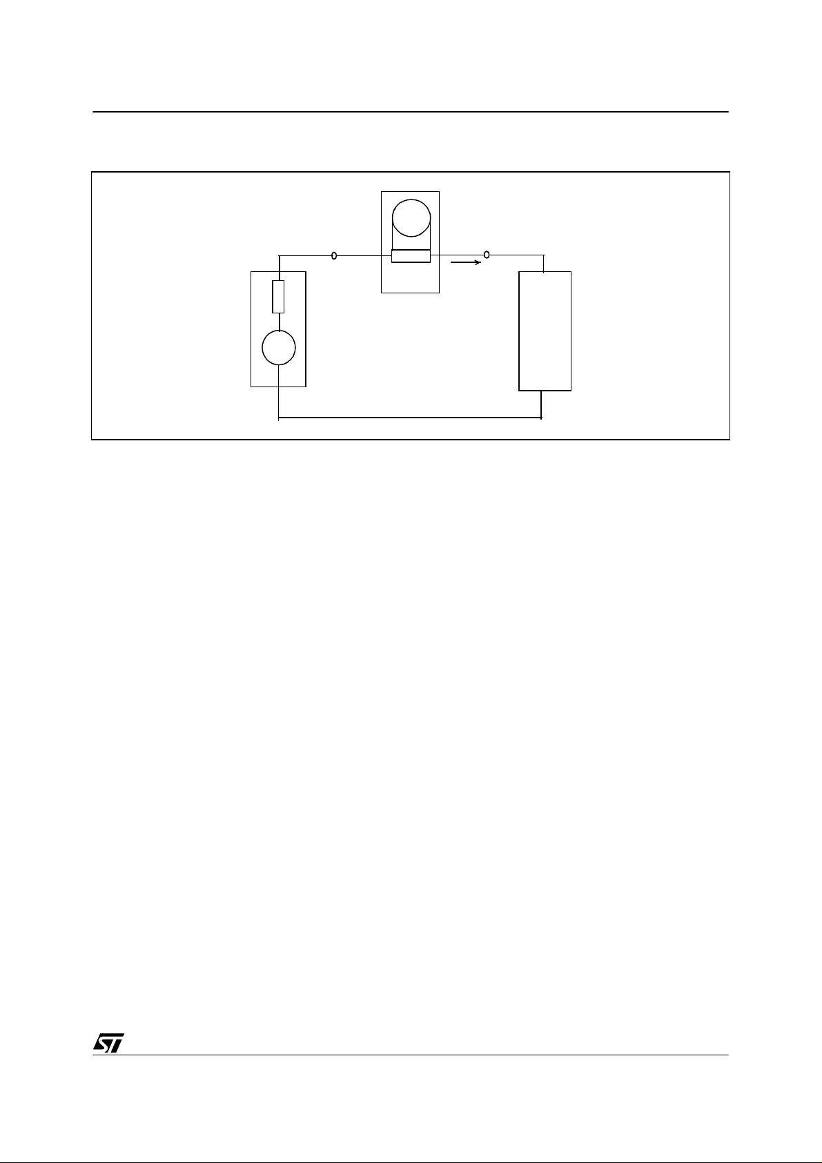
Figure 1. Measurement circuit for single phase equipment
M
zM
ZS
S
Legend:
S = Supply source
M = Measurement equipment
A = Equipment under test
M = Input impedance of measurement equipment
Z
s = Internal impedance of the supply source
Z
n = Harmonic component of order n of the line current
I
G
~
In
A
3/10
Page 4

HOW TO REDUCE 3rd HARMONICS WITH ST6200C MOTOR CONTROL SOFTWARE
1.4 GENERAL RE QUIREMENTS AND LIMITS FOR EQUIPMENT
For Class A equipment (including universal mot ors), the har monics of the input current s hall
not exceed the absolute values given in Table 1. The li mits are given as absolute values which
are independent of the equipment input power.
Table 1. Limit of harmonic currents for Class A equipment
Odd harmonics
Even harmonic s
Harmonic order
3
5
7
9
11
13
≤n≤39
15
2
4
6
≤n≤40
8
Maximum permissib le harmon ic
current(A)
2.30
1.14
0.77
0.40
0.33
0.21
0.15* 15 / n
1.08
0.43
0.30
0.23 * 8 / n
4/10
Page 5

HOW TO REDUCE 3rd HARMONICS WITH ST6200C MOTOR CONTROL SOFTWARE
0000
0000
0000
0000
0000
0000
0000
0000
0000
0000000000000000000
0000000000000000000
0000000000000000000
0000000000000000000
0000000000000000000
0000000000000000000
0000000000000000000
0000000000000000000
0000000000000000000
0000000000000000000
0000000000000000000
0000000000000000000
0000000000000000000
0000000000000000000
0000000000000000000
0000000000000000000
0000000000000000000
0000000000000000000
2 CONTROL PRINCIPLE
2.1 SYMMETRICAL PHASE CONTROL M ETHOD
In AC power system app lications, the amoun t of power del ivered to the syste m load can be
varied by controlling the phase delay time thr ough a TRIAC. The delay time is referred to the
zero voltage crossing on the power line. This method is widely used in uni versal motor control
applications. The motor speed can be easily controlled by changing the firing angle. Power delivered is equal to the integration of the power fr om fire angl e to pi e ( 180 degrees) . The T RIAC
will conduct power aft er the firing angle a nd turn off powe r at the zero cro ssing point. The
system block diagram and waveform are shown in Figure 2..
Figure 2. Topology of universal motor symmetrical phase angle control method
Umot
Umot
M
M
ST6200C
ST6200C
ST6200C
M
Imotor
Imotor
TRIAC
TRIAC
TRIAC
A universal motor operating at reduced speed (i.e firing angle at around 90 degree) produces
very high level of odd harmonics. In experiments with a 1500kW vacuum cleaner at 230V/
50Hz with the same load, harmonic currents were found to be outside the limits when running
at reduced power levels from 470W to 1200W. Practical experience shows that 3rd harmonic
currents are determined not only by the motor current amplitude, but also by the conduction
time.
∆∆∆∆ I
∆∆∆∆ I
5/10
Page 6

HOW TO REDUCE 3rd HARMONICS WITH ST6200C MOTOR CONTROL SOFTWARE
Table 2. 1500W vacuum cleaner harmonic currents measurement at fixed load
with symmetrical phase angle control method
Power Delay time Harmonic order & Harmonic Currents (A)
P (W) t (ms) 3 5 7 9
250 6.9 1.918 0.92 0.275 0.2
320 6.5 2.122 0.931 0.322 0.213
535 5.75 2.474 0.92 0.453 0.175
590 5.55 2.513 0.923 0.478 0.156
780 5.0 2.601 0.883 0.502 0.127
900 4.5 2.576 0.859 0.44 0.162
1000 4.2 2.515 0.834 0.357 0.196
1050 4.0 2.448 0.82 0.306 0.194
1090 3.75 2.406 0.806 0.27 0.188
1130 3.6 2.331 0.793 0.232 0.182
1200 3.5 2.193 0.743 0.188 0.142
1300 3.0 1.892 0.612 0.196 0.06
1400 2.25 1.386 0.33 0.2 0.116
1450 1.6 1.11 0.138 0.13 0.111
1480 0.3 0.77 0.107 0.022 0.01
Harmonic current limit (A) 2.30 1.14 0.77 0.4
In Table 2., the figures in bold are outside the harmonic current limit specifications.
2.2 ASYMMETRICAL PHASE CONTROL METHOD (KURZ PATENT)
The experiment results in Table 2. indicates that universal motors produce the maximum 3rd
harmonic currents at the middle power range. This makes it possible to reduce the harmonic
current with the asymmetrical phase control method.
According to Table 2., when a 1500W v acuum cleaner works at 780W, the 3rd harmonic current is outside the limit. But when it works at 1200W and 320W , the 3rd harmoni c current is
within the limit. If it works at 1200W and 320W in alternate full wave cycles (2 lon g plus 2
short), the 3rd harmonic current should not be outside the limits due to phase considerations
and the average power should be around 760W. The motor speed will be still quite stable due
to to the rotor momentum. The experiment results in Table 3 prove this hypothesis.
It is very simple to try out this control method with a simple experiment. During the testing period, two potentiometers can be used to set two independent phase angle delay times. In this
way, the motor power can be changed with different c om b inations of the two potentiometers.
The motor power and 3rd harmonic current can be measured at the same time. The best harmonic performance can be achieved by finely adjusting the two phase angle delay times.
From this, it is easy to build a look up table (t1 and t2 corresponding to the motor power).
6/10
Page 7

HOW TO REDUCE 3rd HARMONICS WITH ST6200C MOTOR CONTROL SOFTWARE
The current wave form is shown in Table 3. Channel 1 is the AC mains voltage waveform,
channel 4 is the motor current waveform.
Figure 3. . Motor current waveform of asymmetrical phase control method
Based on the simple experiment with two potentiometers, the two phase angle delay time
could be optimized at different motor power rates. From this, the look up table for the two
phase angle delay times can be created . With this innovative solution, the 3rd harmonic currents at middle power range have been reduced dramatically without any additional cost.
Table 3 gives the harmonic currents test resul ts with the same universal motor under the same
test conditions.
Table 3. . 1500W vacuum cleaner harmonic currents measurement at fixed load with
asymmetrical phase angle control method
Power Delay time Harmonic order & Harmonic Currents (A)
P (Watt) t
535W 6.8 5.25 2.13 0.536 0.18 0.059
580W 6.8 5.0 2.033 0.38 0.151 0.104
780W 6.6 4.1 1.745 0.165 0.164 0.21
940W 6.0 3.4 1.557 0.18 0.252 0.134
1000W 6.0 2.9 1.241 0.327 0.29 0.083
1050W 5.55 2.05 0.86 0.388 0.207 0.146
1100W 5.25 2.05 1.01 0.342 0.261 0.106
1120W 4.75 2.05 1.267 0.25 0.316 0.015
Harmonic current limit (A) 2.30 1.14 0.77 0.4
1 (ms) t2 (ms)3579
(Kurz patent)
7/10
Page 8

HOW TO REDUCE 3rd HARMONICS WITH ST6200C MOTOR CONTROL SOFTWARE
This method has already been patented by KURZ. The patent num ber is DE19705907A1
(German Patent) and EP0859452A1 (European Patent). With the KURZ patented method, the
motor current is modulated by two long half waves and two short half waves. In short, this
method can be called the “two long plus two short” method.
8/10
Page 9

HOW TO REDUCE 3rd HARMONICS WITH ST6200C MOTOR CONTROL SOFTWARE
3 CONCLUS IONS
3.1 BUILT-IN ST62 FEATUR ES YIELD THE LOWEST TOTAL SYSTEM COST
The use of MCU-driven motor control s ystem in home appl iances i s becoming more and more
popular with the availability of flexible, reliable and low cost microcontrollers.
The STMicroelectronics ST62 microcontroller family is ideal for hom e applicances because it
offers many powerful on-chip peripherals and resources, a wide range of operating voltages,
built-in ruggedn ess and excelle nt noise imm unity to enab le designers to ac hieve the lowes t
possible system cost.
3.2 A SOFTWARE APPROACH PROVIDES A VERY CO ST EFFECTIVE SOLU TION
The design pre sented pr oposes a cost effecti ve soluti on for reduc ing the 3rd harmoni c currents for v acuum cleane r app lication s. The resul ts given by the experi ments prove th e effi ciency of this method.
The source code of the software (filename vacuum.st6) is supplied with the UMC01EVAL
board. Please contac t your local STMicroelectronics sales office for information about ordering this kit.
9/10
Page 10

HOW TO REDUCE 3rd HARMONICS WITH ST6200C MOTOR CONTROL SOFTWARE
“THE PRESENT NOTE WHICH IS FOR GUIDANCE ONLY AIMS AT PROVIDING CUSTOMERS WITH INFORMATION
REGARDING THE IR PRO DUCT S IN OR DER FO R THEM TO SAV E TIME . AS A RES ULT, STMIC ROEL ECTR ONI CS
SHALL NOT BE HELD LIABLE FOR ANY DIRECT, INDIRECT OR CONSEQUENTIAL DAMAGES WITH RESPECT TO
ANY CL AIM S AR IS IN G FR OM T HE CO N TENT OF S UC H A NO TE A ND /O R T HE U SE M AD E BY C US TO ME RS O F
THE INFORMATION CONTAINED HEREIN IN CONNEXION WITH THEIR PRODUCTS.”
Information furnished is believed to be accurate and reliable. However, STMicroelectronics assumes no responsibility for the consequences
of use of such information nor for any infringement of patents or other rights of third parties which may result from its use. No license is granted
by implic ation or otherwise under any patent or patent r i ght s of STMi croelectr oni cs. Spec i fications mentioned i n this publication are subject
to change without notice. This publication supersedes and replaces all information previously supplied. STMicroelectronics product s are not
authorized for use as cri tical comp onents in lif e support devi ces or systems without the express written appr oval of STMic roelectronics.
The ST logo is a registered trademark of STMicroelectronics
2002 STMicroelectronics - All Rights Reserved.
STMicroelectronics Group of Compan i es
http://www.s t. com
Purchase of I
2
C Components by STMicroelectronics conveys a license under the Philips I2C Patent. Rights to use the se components in an
2
I
C system i s granted pro vi ded that the sy stem conforms to the I2C Standard Specification as defined by Philips.
Australi a - B razil - Canada - China - Finl and - Franc e - Germany - Hong Kong - Ind i a - Is rael - Ital y - J apan
Malaysi a - M al ta - Morocco - Singapore - Spain - Sw eden - Switzerland - Uni ted Kingdom - U.S.A.
10/10
 Loading...