

Page 1
AN1445
APPLICATION NOTE
USING THE ST7 SPI TO EMULATE A 16-BIT SLAVE
By Microcontroller Division Applications
INTRODUCTION
This application note describes how to emulate a 16-bit slave SPI using an ST7 microcontroller with an on-chip 8-bit SPI.
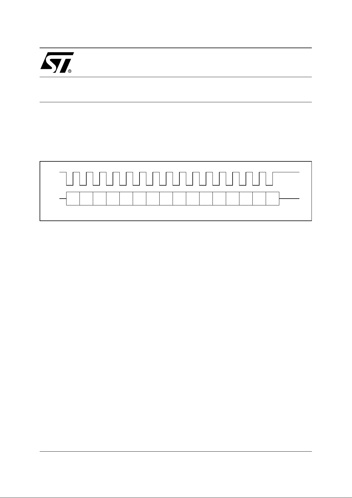
Figure 1. 16-bit SPI frame
bit 0 bit 1 bit 2 bit 3 bit 4 bit 5 bit 6 bit 7 bit 8 bit 9bit 10 bit 11bit 12bit 13bit 14bit 15
1 PRINCIPLE
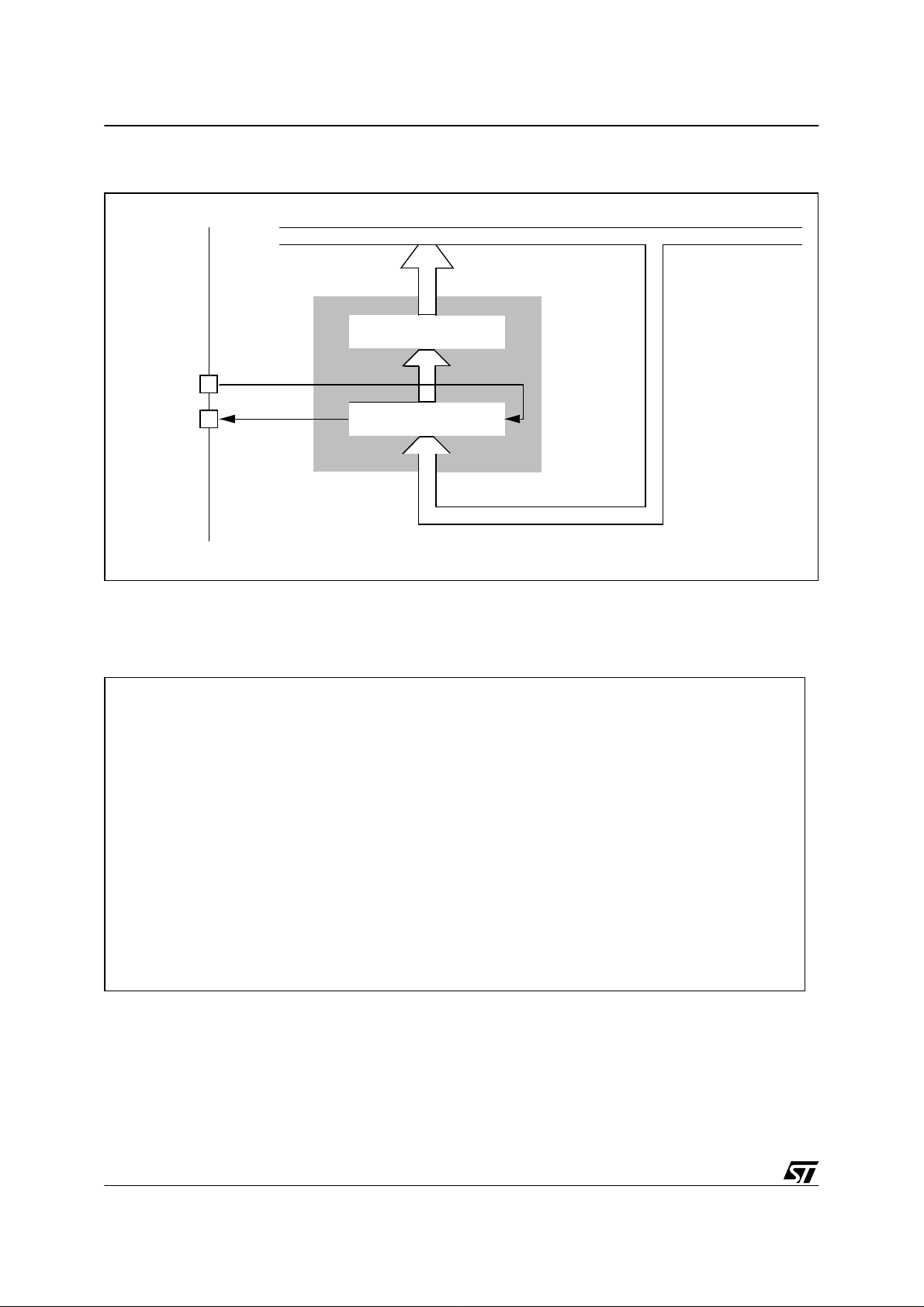
The ST7 SPI cell has a double buffer for receiving data us ing two 8-bit registers: a read register and a shift register (see Figure 2.). The application software accesses the read register to
retrieve the received data. The 8-bit shift register is managed by hardware to receive the 8 bits
of each byte. As each bit is received, it is shifted into the s h ift register . During byte reception,
the read regist er is no t cha nge d. It co ntains the pr evio usly r eceiv ed by te wh ich c an still b e
read by soft wa re. At the en d o f b yte r ecep tion, the 8-bi t shift re gister is c op ied i nto the r ea d
register.
This double buffering makes it possible to receive 16-bit words. At the end of reception of the
first byte, the shift register is copied into the read register, the SPIF flag is set and an interrupt
can be generated. The next in-coming byte will be received in the shift register while the first
byte is available in the read regi ster. In order not to lose any bits, the software mus t be fast
enough to read the first byte before the end of the reception of the second one.
Note: The SPISR (SPI Status Regi ster) is also called SP ICSR (SPI Contr ol/Status Re gister)
depending on which ST7 microcontroller device you use. In this application note, we’ll use the
name SPISR for the status register.
AN1445/1101 1/7
1
Page 2
USING THE ST7 SPI TO EM ULATE A 16-BIT SLAVE
Figure 2. Data Register Block diagram
INTERNAL BUS
DATA REGISTER
READ REGISTER
MOSI
MISO
SHIFT REGISTER
8-BIT
2 SOFTWARE
Figure 3. C code (COSMIC C Com piler) for the interrupt routine
@interrupt @nostack void SPI_Interrupt(void)
{
volatile TwoBytes twobytesDR;
if (ValBit(SPISR,SPIF)) // if a byte is received (SPIF=1) + first step to clear int flags
{
twobytesDR.b_form.low=SPIDR; //1st byte storage
while(ValBit(SPISR,SPIF));
twobytesDR.b_form.high=SPIDR; //2nd byte storage
}
else // then MODF flag caused the interrupt -> add your own code here
{
SPICR=0xC4; // second step to clear MODF flag: write access to SPICR (init value)
}
}
2/7
2
Page 3

USING THE ST7 SPI TO EMULATE A 16-BIT SLA VE
Figure 4. Disassembled interrupt routine code
_SPI_Interrupt:
btjf _SPISR,#7,L501
ld a,_SPIDR
ld _SPI_Interrupt$L-1,a
L311:
btjt _SPISR,#7,L311
ld a,_SPIDR
ld _SPI_Interrupt$L-2,a
iret
L501:
ld a,#196
ld _SPICR,a
iret
where:
typedef unsigned char u8; /* unsigned 8 bit type definition */
typedef signed char s8; /* signed 8 bit type definition */
typedef unsigned int u16; / * unsigned 16 bit type definition */
typedef signed int s16; /* signed 16 bit type definition */
typedef unsigned long u32; / * unsigned 32 bit type definition */
typedef signed long s32; / * signed 32 bit type definition */
typedef union { /* unsigned 16 bit type for 8 & 16 */
u16 w_form; /* bit accesses: 16> var.w_form */
struct { /* 8> var.b_form.high/low */
u8 high, low;
} b_form;
} TwoBytes;
Note: On some devices, another flag called OVR (overrun) can also cause an SPI interrupt to
occur. In this case, you will have to add some code to the interrupt routine to handle this.
3/7
Page 4

USING THE ST7 SPI TO EM ULATE A 16-BIT SLAVE
3 MAXIMUM BAUD RATE
The baud rate is limited by the speed of the ST7 SPI hardware, which runs at 2 MHz maximum
(for a master @ f
software to read the data register before the end of the reception of the second byte.
The time needed to release the data register is 4 microseconds at 2 MBaud. The time needed
by the software consists of:
■ The interrupt context switching: worst case: 2,75us
Firstly, the current instruction must finish: worst case: multiply instruction: 12 cycles =
1,5us @ 8 MHz internal. Secondly the hardware needs 10 cycles = 1,25µs @ 8 MHz internal frequency to save the context before jumping to the interrupt routine.
■ A read access to the status register: 0,625µs
btjf _SPISR,#7,L501 takes 5 cycles = 0,625µs
■ A read access to the data register: 0,375µs
ld a,_SPIDR takes 3 cycles = 0,375µs
= 8 MHz). We can calculate if this baud rate allows enough time for the
CPU
Figure 5. Data Reception Timing Analysis
bit 0 bit 1 bit 2 bit 3 bit 4 bit 5 bit 6 bit 7 bit 8 bit 9bit 10 bit 11bit 12bit 13bit 14bit 15
- Interrupt
- SPIF set
- Read register = shift register
interrupt
context
switching
read
SR
read
DR
2,75 us 0,625 0,375
4 us (8*500ns)
Deadline
Values at f
CPU
The time needed by the software is 30 cycles = 3,75us < 4us.
4/7
=8 MHz, Baud rate = 2 MHz
Page 5

USING THE ST7 SPI TO EMULATE A 16-BIT SLA VE
In the case of concurrent interrupts, the SPI interrupt must always be the first served. The only
way to ensure this happens is to have only the SPI interrupt enabled. Otherwise, if another interrupt is served between two received words, an overrun condition will occur.
In the case of nested interrupts, the SPI interrupt only needs to have the highest priority, to be
always immediately served.
CONCLUSION: The m aximum baud rate, which can be reached is 2 MBaud.
4 MEASUREMENTS
The goal of the meas urement is to ve rify the abov e theory and to see whethe r the software
correctly receives both bytes. What is especially important is the time needed to r ead the data
register, w hic h re leas es t he shi ft regis ter for the re cepti on of t he 2nd b yte. To mea su re t his
time an I/O port pin is used and cleared after reading the data register. The interrupt routine is
therefore slightly modified for the measurement (Figure 6.) . The tim ing cond itions are: SPI
baud rate = 2 Mbaud and f
Figure 6. Measurement Software
CPU
= 8 MHz.
C code Assembly code
_SPI_Interrupt:
if (ValB it(SPISR,SPIF))
{
twobytesDR.b_form.low=SPIDR;
PBDR=0x00;
while(!ValBit(SPISR,SPIF));
twobytesDR.b_form.high=SPIDR;
PBDR=0xFF;
}
else
{
SPICR=0xC4;
}
btjf _SPISR,#7,L522
ld a,_SPIDR
ld _SPI_Interrupt$L-1,a
clr _PBDR
L332:
btjf _SPISR,#7,L332
ld a,_SPIDR
ld _SPI_Interrupt$L-2,a
ld a,#255
ld _PBDR,a
iret
L522:
ld a,#196
ld_SPICR,a
iret
The time to be measured is the time taken by the “LD a,SP IDR” instruction (Ax in Figure 7.).
The point we can measure is the transition when the port pin goes low (Bx in Figure 7.). T he
time betwee n both is the time needed by “ld _SP I_Interru pt$L-1,a “and “cl r PBDR”, which is
4cy+5cy=1,125us. So to Ax is 1,125us before Bx.
The measurement shows that Ax is always before the deadline. This proves that the 8-bit SPI
can be used to receive 16-bit SPI messages at speeds up to 2MBaud.
5/7
Page 6

USING THE ST7 SPI TO EM ULATE A 16-BIT SLAVE
Figure 7. Read time measurement
6/7
Page 7

USING THE ST7 SPI TO EMULATE A 16-BIT SLA VE
“THE PRESENT NOTE WHICH IS FOR GUIDANCE ONLY AIMS AT PROVIDING CUSTOMERS WITH INFORMATION
REGARDING THE IR PRO DUCT S IN OR DER FO R THEM TO SAV E TIME . AS A RES ULT, STMIC ROEL ECTR ONI CS
SHALL NOT BE HELD LIABLE FOR ANY DIRECT, INDIRECT OR CONSEQUENTIAL DAMAGES WITH RESPECT TO
ANY CL AIM S AR IS IN G FR OM T HE CO N TENT OF S UC H A NO TE A ND /O R T HE U SE M AD E BY C US TO ME RS O F
THE INFORMATION CONTAINED HEREIN IN CONNEXION WITH THEIR PRODUCTS.”
Information furnished is believed to be accurate and reliable. However, STMicroelectronics assumes no responsibility for the consequences
of use of such information nor for any infringement of patents or other rights of third parties which may result from its use. No license is granted
by implic ation or otherwise under any patent or patent ri ghts of STM i croelectr oni cs. Spec i fications mentioned i n this publication are subje ct
to change without notice. This publication supersedes and replaces all information previously supplied. STMicroelectronics products are not
authorized for use as cri tical comp onents in life support dev i ces or systems wi thout the express written approv al of STMicroel ectronics.
The ST logo is a registered trademark of STMicroelectronics
2001 STMicroelectronics - All Rights Reserved.
STMicroelectronics Group of Compan i es
http://www.s t. com
Purchase of I
2
C Components by STMicroelectronics conveys a license under the Philips I2C Patent. Rights to use the se components in an
2
C system i s granted pro vi ded that the sy stem conforms to the I2C Standard Specification as defined by Philips.
I
Australi a - B razil - Canada - China - Finl and - France - Germany - Hong Kong - Ind ia - Israel - Italy - Japan
Malaysi a - M al ta - Morocco - Singapore - Spain - Sw eden - Switz erland - United Kingdom - U.S.A.
7/7
 Loading...