

Page 1

AN1324
APPLICATION NOTE
CALIBR ATING THE RC OSCIL LATOR OF THE
ST7F LITE 0 M C U US ING T HE MAI NS
INTRODUCTION
The ST7FLITE0 microcontroller contains an internal RC oscillator which can be trimmed to a
specific freq uency wi th an accura cy of 1%. The oscilla tor frequen cy has to be calibrated by
softwa re u sing the R CCR ( RC Con trol Regi ster ). T he val ue e nte red in t he RCCR will swi tch on
a corresponding number of resistors that will modify the oscillator frequency. Whenever the
ST7FLITE0 microcontroller is reset, the RCCR is restored to its default value (FFh), so each
time the device is reset, you have to load the calibration value in the RCCR. There are predefined calibration values stored in memory (refer to section 7.1 in the ST7FLITE0 datasheet)
You can loa d on e o f th ese v alu es i n th e RCCR if on e of t he op erating c on dit ions match es t h at
in your application. Otherwise, you can define your own value, store it in EEPROM or any nonvolatile memory and load it in the RCCR register after each reset. However, if any of the external conditions (temperature or voltage, for instance) change too drastically, the s tored value
may no longer produce the required 1% accuracy. One solution is to recalculate the RCCR
value after each reset, based on an external reference.
The purpose of this app lication no te is to pres ent a sof tware s olution using the freque ncy o f
the European standard mains (220V/50Hz) as a timebase to adj ust the internal RC oscillator
of the ST7FLITE0 to 1 MHz (1%). The same approach can also be used for the US mains
standard (110V/60Hz).
The basic software takes less than 160 ms to calibrate the oscillator and uses less than 90
bytes of progra m memo ry and five byte s of RAM for it s simplest vers ion. The se RAM bytes
can be freed for other pur poses when the calibration i s done. Another example using averages
is given in this application note. This can be useful with noisy mains
This application note also contains the diagram of a low cost circuit which converts the mains
into a 5 volt power supply and protects the microcontroller from overcurrent on the input connected to the mains.
Rev. 2
AN1324/0604 1/15
1
Page 2
CALIBRATING THE RC OSCILLATOR OF THE ST7FLITE0 MCU USING THE MAINS
1 CALIBRA TION SOFTWARE
1.1 SOFTWARE PR INCIPLE
The softwar e algorith m, descri bed in the fo llowing fl owcha rt (see Figu re 3), uses the mains
frequency as a timebase. This timebase allows the m icrocontr oller to test i f the RC os cillator
frequency is above or below 1 MHz and repeatedly transforms it by dichotomous analysis so
that in 7 iterations the RCCR is set to the optimum value.
As the timer speed depends on the RC oscillator frequency, it is easy to determine if the oscil lator is too fast or too slow. The counted value can be obtained by the following equation:
f
count edval ue
Since the frequency of the counter is the frequency of the oscillator divided by 32, if the oscillator is at 1 MHz, the result of the count between two edges (which have a 10 ms interval), is
138h for the European standard (220V/50Hz). For the US standard (110V/60Hz) the right
value is 104h. Since the goal of the software is to set the RC oscillator frequency to 1 MHz it
means obtainin g 13 8h as the result of the c oun t. S o if the resu lt o f the c ount is gr eater t han
138h, it means that the frequency is too high so the program increases the value of RCCR in
order to decrease the RC oscillator frequency. And if th e result is less than 138h, the RCCR is
decreased in order to increase the RC oscillator frequency.
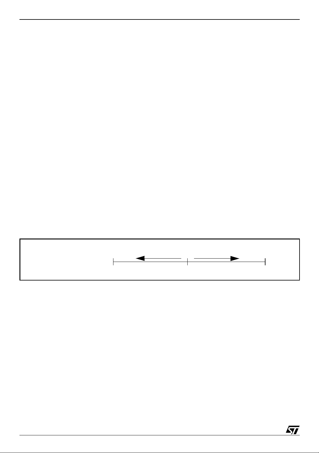
Figure 1. Dichotomous Analysis of RCCR Value
-------------------------- -=
32 f
×
cpu
mains
increase oscillator
frequency
decrease oscillator
frequency
RCCR Register
80h
FFh0h
Start Value
The RCCR register is set to 80h initially by the program, then the dichotomization starts by
adding or subtracting 40h and after eac h iterati on the result is di vided by two, so that after 7 it erations the value of RCCR is set with an accuracy of one bit.
2/15
2
Page 3
CALIBRATING THE RC OSCILLATOR OF THE ST7FLITE0 MCU USING THE MAINS
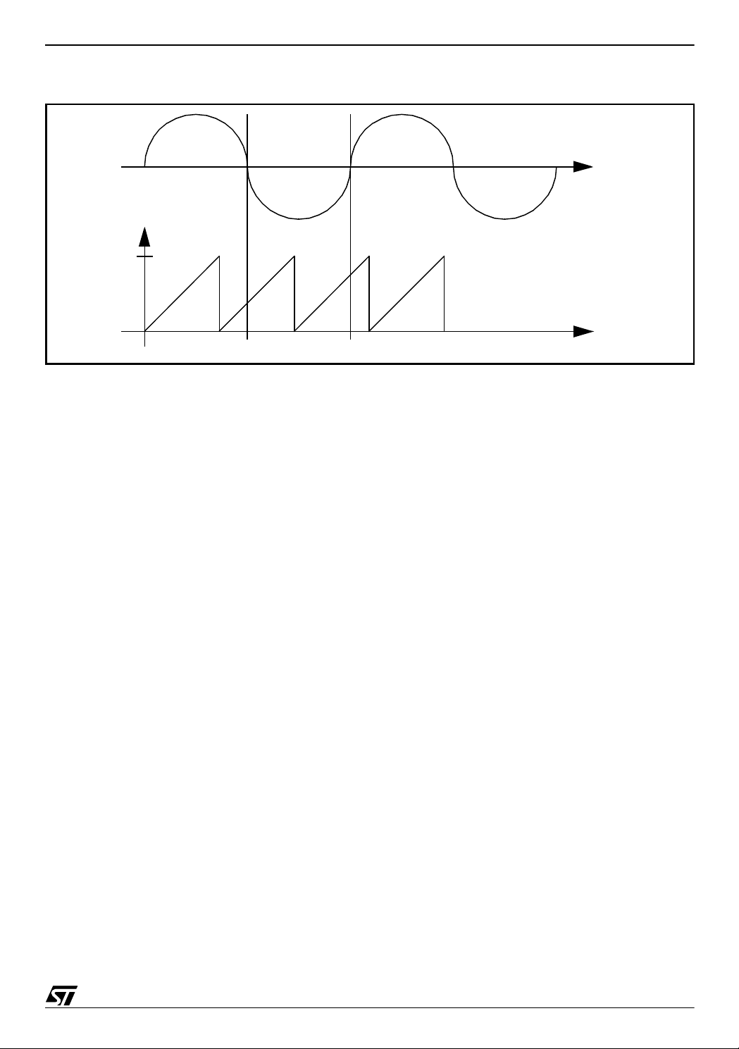
Figure 2. Using the Timer Input Capture to Measure the Mains Frequency
Mains
F9h
Overflow
Free-running
Counter
0h
Capture 1 Capture 2
To measure the frequency, the softwar e uses the Lite Timer input capture (LTIC) so that on
each edge of the mains the value of the free running counter is stored as shown in Figure 2.
Then the microcontroller calculates the elapsed time between the two edges of the mains.
This time is given by the following equation:
time nbover F9h capture2 capture1–+×=
where nbover represents the number of counter overflows during the measurement, capture 1
and capture 2 are the values captured on the free running counter when an edge occurs on
the mains and F9h is the overflow value of the free running counter.
If the RC oscillator frequ ency is equal to 1 MHz, the result time will be 138h for European
standard (220V/50Hz) or 104h for US standard mains (110V/60Hz), so these are the reference values.
This measurement result is compared to the reference value and, depending on the result of
the comparison, the microcontroller adds to or subtracts from the current RCCR value.
3/15
Page 4

CALIBRATING THE RC OSCILLATOR OF THE ST7FLITE0 MCU USING THE MAINS
1.2 BASIC VERSION
In this version the measurement is done only once for each dichotomization step. This allows
the calibration software to be l ight and fast. It requires only 90 bytes of program mem o ry and
5 bytes of RAM during calibration. The calibration takes less than 160 ms to be completed
The software works as shown in the following flowchart. The assembly code and a more detailed flowchart can be found in Section 4.
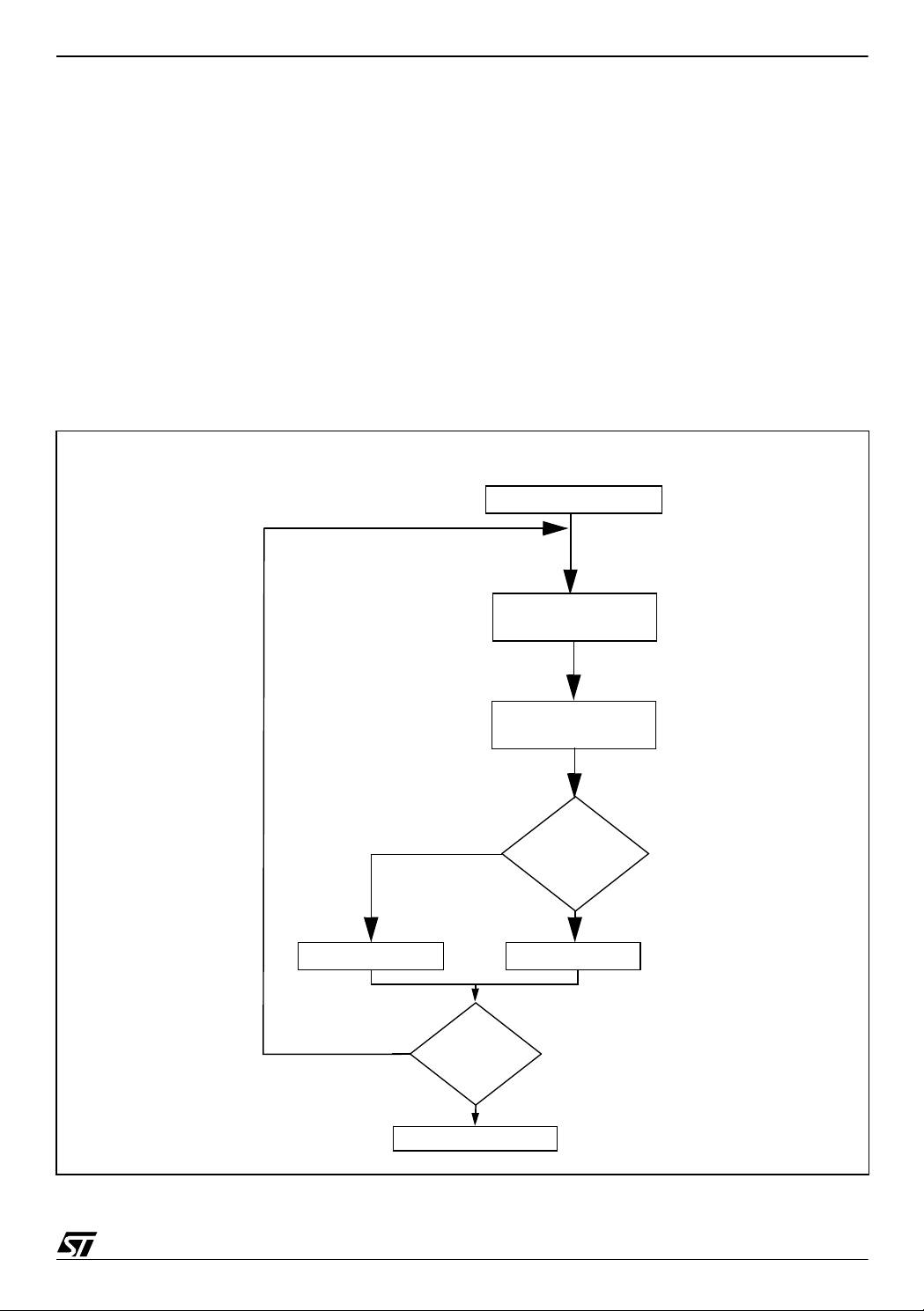
Figure 3. Basic software flowchart
Initialization of Lite Timer
Measurement and
calculation
smaller
no
Dichotomization
finished?
Clock is set to 1 MHz
Compare
result with
reference
greater or equal
Increase RCCRDecrease RCCR
yes
4/15
Page 5
CALIBRATING THE RC OSCILLATOR OF THE ST7FLITE0 MCU USING THE MAINS
1.3 AVERAGE VERS ION
This version uses the method described in Section 1.1 except it performs four measurements
and uses their average for each di chotomization step. It i s useful w hen the mains is noi sy. F or
instance, when a motor starts it generates a tension pick and this can be considered as a
mains edge.
This version is safer than the basic one but it requires more res ources. It uses 13 6 bytes of
program memory and 11 bytes of RAM during calibration. The calibration takes less than 560
ms to be completed.
The average version w orks as shown in the following flowc hart. The assem bly code can be
found in Section 4.
Figure 4. Average software flowchart
Initialization of Lite Timer
no
smaller
Dichotomization
finished?
yes
4 measurements and
calculation
Average
Compare
result with
reference
greater or equal
Increase RCCRDecrease RCCR
Clock is set to 1 MHz
5/15
Page 6

CALIBRATING THE RC OSCILLATOR OF THE ST7FLITE0 MCU USING THE MAINS
2 POWER SUPPLY AND TIMEBASE DELI VERY CIRCUIT
The following figures show circuits which will provide 5V DC to the ST7LITE0 and protect the
input capture from overcurrent. If no power suppl y is needed, the only component to keep is
the resistor on the LTIC input, which is mainly to protect from over cur rent.
2.1 BASIC CIRCUIT
This circuit contains a capacitive power supply which converts the 220V/50Hz of the mains, as
well as the 110V/60Hz of the US m ains, i n to 5V DC.
Warning: be aware that this kind of power supply can’t be used if there are big current variations.
It also inputs 220V/50Hz to the Lite Tim e r Input Capture pin (LTIC/PA0) protected by resistor
R2.
The incoming alternating signal on the LTIC input pin is 220V/50Hz. Because of the clamping
diode on the input of the ST7FLITE0, the input signal can be considered as a 0-5V square
signal.
Figure 5. Power supply and timebase delivery circuit diagram
V
DD
C1
220uF/16V
ST7Lite0
GND
LTIC
Mains
(220V/50Hz)
R1 47R/0.5W
zener
5.6V
1N4148
C2
C2
220nF/400V
R2 470k/0.5W
The maximum current available in the microcontroll er depends on the C2 value. Table 1 gi ves
the maximum average current versus the capacitor value. The average current follows the
equation below:
Imax Vmax 2 fC⋅⋅⋅=
6/15
Page 7

CALIBRATING THE RC OSCILLATOR OF THE ST7FLITE0 MCU USING THE MAINS
In the case ab ove, C2 i s equal to 220 nF so th e availab le cur rent is limit ed to 4.9 mA in the
case of a European mains. To have the same current levels in the case of the US mains
(110V/60Hz), C2 must be multiplied by two. A 440nF capacitor will limit the current to 4.9 mA.
For the US standard, R2 must be divided by two in order not to limit the current too much on
the LTIC input. A 220k resistor is enough in this case.
Table 1. Maximum MCU Current
CAPACITOR C2 MAXIMUM CURRENT
220nF 4.9mA
330nF 7.3mA
470nF 10.4mA
680nF 15mA
1uF 22.1mA
2.2 HARDWARE PROTECTION
To prevent bad measurements due to noisy m ains, a filter can be add ed between the mains
and the input capt ure of the LITE0 . The follow ing figure shows one exa mple of a filter. T his
filter is a pa ss ban d centere d on the main s freque ncy in order to re ject all freque ncy whi ch
could be understood by the microcontroller as a mains edge.
Be aware that this is just a second order filter and that this may not be enough if the mains is
really noisy. Any kind of filter can be added on the LTIC.
Figure 6. Band pass filter
mains
C1
R1 R2
R3
LTIC
470nF/400V
C2
C2
470nF/400V 470nF/250V
The pass band filter above must be tuned to m ains fr equency . The value o f the r esistors for
this filter is given in the table below.
Table 2. resistors values
resistors 50Hz/220V 60Hz/110V
R1 6.8K/0.5W 5.6K/0.5W
R2 6.8K/0.5W 5.6K/0.5W
R3 470K/0.5W 220K/0.5W
7/15
Page 8

CALIBRATING THE RC OSCILLATOR OF THE ST7FLITE0 MCU USING THE MAINS
3 CONCLUSION
This system allows you to have a power supply for the microcontroller and an auto adjustable
clock set to 1MHz with an accuracy of 1% whatever the extern al conditions.
This solution also offe rs the a dvan tage of bein g les s expe nsive tha n a so lution wit h a transformer and requires less space.
It requires a small amount of space in program memory (less than 90 bytes) in its s mallest version.
8/15
Page 9

CALIBRATING THE RC OSCILLATOR OF THE ST7FLITE0 MCU USING THE MAINS
4 SOFTWARE EXAMPLES
A zip file attache d to this ap plicati on note cont ains the com plete software of this calibra tion
method.
4.1 SINGLE ALTERNANCE
This version perform only one count between two edges and changes the value of the RCCR
according to this measurement. This can lead to bad tuning if there is noise on the reference
signal.
4.1.1 main program
;All the bytes from locations 80h to 85h are used by this software to store values or as control
registers but they can be reused safely after the clock has been set.
;dichotomy value
.value equ $81 ;this byte contains the value which will be added
or subtracted to/from the RCCR last value at the end of each round
;capture values
.capture1 equ $82
.capture2 equ $83 ;these two bytes contain the two values of the counter
captured on the edge of the mains, they are used to calculate the time elapsed between the two
edges
;number of overflows
.nbover equ $84 ;this byte contains the number of counter overflows
during the measurement
;control register
.cr equ $85 ;this byte is used as a control register for the measurement. Its bits allow or not the interrupts and show which step of the count is the current one.
.strtstp equ 1 ;this is set to start the count and reset to stop it
.overflow equ 2 ;this bit is set when the first capture has occurred. It
allows the overflows to be counted
.main
bset MCCSR, #1 ;output clock enable. You can remove this line if you do
not want to check the clock
ld A, #$80 ;value containing the value which will be
ld value, A ;add or subs to/from RCCR during the dichotomy
ld RCCR, A ;RCCR is set to the middle of its range of value
next clr nbover ;clear the byte containing the number of timer overflow
ld A, LTICR ;clear the ICF bit
count btjt cr, #strtstp, count; wait for the end of count
clr cr ;clear the byte use as control register for the count
rim ;interrupts enable
bset LTCSR, #7 ;enable input capture interrupt
bset cr,#strtstp ;set the start-stop bit of cr: count can start
clr LTCSR ;lite timer interrupts disable
srl value ;dichotomy value divided by 2
ld A,#$F9 ;these lines calculate this equation:
ld X,nbover ;
mul X,A ;(nbover*$F9)+ capture2 - capture1
add A, capture2 ;
9/15
Page 10

CALIBRATING THE RC OSCILLATOR OF THE ST7FLITE0 MCU USING THE MAINS
jrnc nocarry ;this equation is calculated with 16 bits
inc X ;
nocarrysub A, capture1 ;MSB are in register X
noneg cp X, #$01 ;if mains frequency is 50Hz the reference value is $138
comparecp A, #$38 ;value is smaller than the reference the program jump to
plus ld A, RCCR
minus ld A, RCCR
new ld RCCR,A ;enter the new value in RCCR
loop jp loop
jrnc noneg ;
dec X ;and LSB in register A.
jrmi minus ;if it is 60Hz the reference is $104.the program first
jreq compare ;compares MSB with $01 and then compare LSB with
jp plus ;$38 for 50Hz and $04 for 60Hz. if the calculated
jrmi minus ;minus to decrease RCCR else it increase RCCR
add A, value ;add value if counted value is greater than ref
jp new
sub A, value ;subtract value if Y is smaller
btjf value, #0, next;stop after 7 rounds
4.1.2 input capture interrupt
ld A, LTICR ;load captured value in A
btjt LTCSR, #4, finish ;test if it is first or second capture
bset LTCSR, #4 ;allow timebase interrupt in order to count the
number of overflows
ld capture1, A ;captured value is stored in capture1
jp endit1
finish ld capture2, A ;if it is the second capture, captured value is
stored in capture2
clr cr ;clear cr to end the count
endit1 iret
4.1.3 timebase interrupt
ld A, LTCSR ;clear TB bit
inc nbover ;increment number of overflows
endit2 iret
4.1.4 writing in eeprom
To stor e fin al value of R CCR i n EEPRO M, add t he s es l i n es a ft e r di sa bling the t i me r i nt erru pt s
in the main program.
ld RCCR, A
bset EECSR,#1 ;start to enter value in the EEPROM
ld $1003,A ;load value of the RCCR in EEPROM
wait btjt EECSR,#0,wait ;wait for the end of writing in EEPROM
bset EECSR,#0 ;start to write in the EEPROM
10/15
Page 11

CALIBRATING THE RC OSCILLATOR OF THE ST7FLITE0 MCU USING THE MAINS
4.1.5 Detailed basic version software flowchart
STORE STARTING VALUE
80H --> VALUE
80H --> RCCR
CLEA R RAM BYTES
ENABLE INPUT CA PTURE INTERRUPT
(NBOVER, CR)
EDGE
ON LTIC
INPUT
YES
STORE CAPTURED VALUE IN CAPTURE 1
ENABLE TIMEBASE INTERRUPT TO
START TO COUNT TIMER OVERFLOWS
EDGE
ON LTIC
INPUT
YES
STORE CAPTURED VALUE IN CAPTURE 2
DISABLE TIMEBASE AND INPUT CAPTURE
INTERRUPTS
DIVIDE VA LUE BY 2
CALCULATION OF:
NBOVER X F9 + CAPTU RE 2 - CAPT URE 1
NO
NO
GREATER
SMALLER
SUBTRA CT VALUE TO RCCRADD VA LUE TO RCCR
NO
RC OSCILLATOR IS TRIMMED TO 1 MHZ
COMPARE
RESULT WITH
138H
IS THE
DICHOTOMY
FINISHED?
YES
11/15
Page 12

CALIBRATING THE RC OSCILLATOR OF THE ST7FLITE0 MCU USING THE MAINS
4.2 AVERAGE VERS ION
This version perform the c ount between two edg es four times and changes the value of the
RCCR according to the average of these measurements. This method allows to perform a
better tune of the RC oscillator.
4.2.1 main program
;All the bytes from locations 80h to 8Bh are used by this software to store values or as control
registers but they can be reused safely after the clock has been set.
;dichotomy value
.value equ $81 ;this byte contains the value which will be added
or subtracted to/from the RCCR last value at the end of each round
;capture values
.capture1 equ $82
.capture2 equ $86 ;these bytes contain the values of the counter captured
on the edge of the mains, they are used to calculate the time elapsed between the two edges
;number of overflows
.nbover equ $8A ;this byte contains the number of counter overflows
during the measurement
;control register
.cr equ $8B ;this byte is used as a control register for the measurement. Its bits allow or not the interrupts and show which step of the count is the current one.
.strtstp equ 1 ;this is set to start the count and reset to stop it
.overflow equ 2 ;this bit is set when the first capture has occurred. It
allows the overflows to be counted
.main
bset MCCSR, #1 ;output clock enable. You can remove this line if you do
not want to check the clock frequency
ld A, #$80 ;value containing the value which will be
ld value, A ;add or subs to/from RCCR during the dichotomy
ld RCCR, A ;RCCR is set to the middle of its range of value
next clr nbover ;clear the byte containing the number of timer overflow
ld A, LTICR ;clear the ICF bit
capturerim ;interrupts enable
count btjt cr, #strtstp, count; wait for the end of count
calcul add A, (capture2,Y);
clr cr ;clear the byte use as control register for the count
clr Y
bset LTCSR, #7 ;enable input capture interrupt
bset cr,#strtstp ;set the start-stop bit of cr: count can start
clr LTCSR ;lite timer interrupts disable
inc Y
cp Y,#$4 ;repeat the capture four time to make an average
jrne capture
srl value ;dichotomy value divided by 2
clr Y
ld A,#$F9 ;these lines calculate this equation for the four
ld X,nbover ;measures:
mul X,A ;(nbover*$F9)+ capture2 - capture1
jrnc nocarry ;this equation is calculated with 16 bits
inc X ;
12/15
Page 13

CALIBRATING THE RC OSCILLATOR OF THE ST7FLITE0 MCU USING THE MAINS
nocarrysub A, (capture1,Y);MSB are in register X
jrnc noneg ;
noneg inc Y
carry1 srl A
carry2 cp X, #$01 ;if mains frequency is 50Hz the reference value is $138
comparecp A, #$38 ;value is smaller than the reference the program jump to
plus ld A, RCCR
minus ld A, RCCR
dec X ;and LSB in register A.
cp Y,#$4
jrne calcul
srl A ;these lines calculate the average of the last four
srl X ;measures by dividing their total by 4. It is done by
jrnc carry1 ;two consecutive right shift on the 16 bit result.
add A,#$80
srl X
jrnc carry2
add A,#$80
jrmi minus ;if it is 60Hz the reference is $104.the program first
jreq compare ;compares MSB with $01 and then compare LSB with
jp plus ;$38 for 50Hz and $04 for 60Hz. if the calculated
jrmi minus ;minus to decrease RCCR else it increase RCCR
add A, value ;add value if counted value is greater than ref
jp new
sub A, value ;subtract value if Y is smaller
new ld RCCR,A ;enter the new value in RCCR
btjf value, #0, next;stop after 7 rounds
loop jp loop
4.2.2 input capture interrupt
ld A, LTICR ;load captured value in A
btjt LTCSR, #4, finish ;test if it is first or second capture
bset LTCSR, #4 ;allow timebase interrupt in order to count the
number of overflows
finish ld capture2, A ;if it is the second capture, captured value is
stored in capture2
endit1 iret
ld capture1, A ;captured value is stored in capture1
jp endit1
clr cr ;clear cr to end the count
4.2.3 timebase interrupt
ld A, LTCSR ;clear TB bit
inc nbover ;increment number of overflows
endit2 iret
13/15
Page 14

CALIBRATING THE RC OSCILLATOR OF THE ST7FLITE0 MCU USING THE MAINS
4.2.4 Detailed average version software flowchart
STORE STARTING VALUE
80H --> VALUE
80H --> RCCR
CLEAR RAM BYTES
ENABLE INPUT CAPTURE INTERRUPT
(NBOVE R , CR )
EDGE
ON LTIC
INPUT
YES
STORE CAPTURED VALUE IN CAPTURE 1.X
ENABLE TIMEBASE INTERRUPT TO
START TO COUNT TIMER OVERFLOWS
EDGE
ON LTIC
INPUT
YES
STORE CAPTU RED VALUE IN CAPTURE 2.X
DISABLE TIMEBA SE AN D INPUT CAPTU RE
NO
NBOVER X F9 + 4(CAPTURE2.X - CAPTURE1.X)
RESULT DIVIDED BY 4 TO AVE RA GE IT
INTERRUPTS
FOUR
MEASUREMENTS
DONE?
YES
CALCULATION OF:
DIVIDE VALUE BY 2
NO
NO
14/15
EQUAL OR GREATER
ADD VALUE TO RCCR
COMPARE
RESULT WITH
138H
SMALLER
SUBTRACT VALUE TO RCCR
NO
RC OSCILLATOR IS TRIMMED TO 1 MHZ
IS THE
DICHOTOMY
FINISHED?
YES
Page 15

CALIBRATING THE RC OSCILLATOR OF THE ST7FLITE0 MCU USING THE MAINS
“THE PRESENT NOTE WHICH IS FOR GUIDANCE ONLY AIMS AT PROVIDING CUSTOMERS WITH INFORMATION
REGARDING THE IR PRO DUCT S IN OR DER FO R THEM TO SAV E TIME . AS A RES ULT, STMIC ROEL ECTR ONI CS
SHALL NOT BE HELD LIABLE FOR ANY DIRECT, INDIRECT OR CONSEQUENTIAL DAMAGES WITH RESPECT TO
ANY CLAIMS ARISING FROM THE CONTENT OF SUCH A NOTE AND/OR THE USE MADE BY CUSTOMERS OF
THE INFORMATION CONTAINED HEREIN IN CONNECTION WITH THEIR PRODUCTS.”
Information furnished is believed to be accurate and reliable. However, STMicroelectronics assumes no responsibility for the consequences
of use of such information nor for any infringement of patents or other rights of third parties which may result from its use. No license is granted
by implic ation or oth erwise unde r any patent or patent r i ghts of STMi croelectroni cs. Speci fications me ntioned in this publicat i on are subject
to change without notice. This publication supersedes and replaces all information previously supplied. STMicroelectronics products are not
authorized for use as critical components in life su pport device s or systems without express written approval of STMicroelectronics.
The ST logo is a register ed t rademark of ST M i croelectroni c s.
All other nam es are the pro perty of their respective ow ners
© 2004 STMi croelectroni cs - All rights reserved
STMicroelectron i cs GROUP OF COMPANIES
Australia – Belgium - B razil - Canad a - China – Czech Republic - Finl and - France - Ger many - Hong Kong - India - Israel - Italy - Japan -
Malaysia - Malta - Morocco - Singapore - Spain - Sweden - Switzerland - United Kingdom - United States
www.st.com
15/15
 Loading...