

Page 1

AN1294
Application note
PowerSO-10RF: the first true RF power SMD package
Introduction
During the last years, as the size of electronic components has decreased and their
reliability increased, there has been a need across the board for various surface-mounted
components. The PowerSO-10RF is not just a new package, it is a new concept in a small
outline plastic package for RF power applications. Such applications have a great need for
surface-mount device (SMD) packages but, up until now, the available bipolar technology did
not allow for such types of package.
The main advantages of this new RF plastic package are excellent thermal performance,
high power capability, high power density and suitability for all reflow soldering methods.
The purpose of this application note is to demonstrate that the PowerSO-10RF is the perfect
solution for the new RF power LDMOS products recently introduced by STMicroelectronics.
November 2009 Doc ID 7604 Rev 3 1/20
www.st.com
Page 2

Contents AN1294
Contents
1 RF Power package requirements . . . . . . . . . . . . . . . . . . . . . . . . . . . . . . . 5
2 What is the PowerSO-10RF? . . . . . . . . . . . . . . . . . . . . . . . . . . . . . . . . . . 6
2.1 Brief overview of the PowerSO-10RF technology . . . . . . . . . . . . . . . . . . . 6
2.2 Delivery information . . . . . . . . . . . . . . . . . . . . . . . . . . . . . . . . . . . . . . . . . . 7
3 Products . . . . . . . . . . . . . . . . . . . . . . . . . . . . . . . . . . . . . . . . . . . . . . . . . . . 8
3.1 Benefits . . . . . . . . . . . . . . . . . . . . . . . . . . . . . . . . . . . . . . . . . . . . . . . . . . . 8
3.2 Segments and applications . . . . . . . . . . . . . . . . . . . . . . . . . . . . . . . . . . . . 8
4 LDMOS in PowerSO-10RF/typical RF performances . . . . . . . . . . . . . . . 9
5 Quality and reliability . . . . . . . . . . . . . . . . . . . . . . . . . . . . . . . . . . . . . . . 11
6 Soldering method . . . . . . . . . . . . . . . . . . . . . . . . . . . . . . . . . . . . . . . . . . 12
6.1 Vapor phase reflow . . . . . . . . . . . . . . . . . . . . . . . . . . . . . . . . . . . . . . . . . . 12
6.2 Infrared heating . . . . . . . . . . . . . . . . . . . . . . . . . . . . . . . . . . . . . . . . . . . . 12
6.3 Soldering paste . . . . . . . . . . . . . . . . . . . . . . . . . . . . . . . . . . . . . . . . . . . . 12
6.3.1 Applying the soldering paste . . . . . . . . . . . . . . . . . . . . . . . . . . . . . . . . . 12
6.4 Placement of parts and drying . . . . . . . . . . . . . . . . . . . . . . . . . . . . . . . . . 13
6.5 Avoiding stresses . . . . . . . . . . . . . . . . . . . . . . . . . . . . . . . . . . . . . . . . . . . 13
7 Mounting recommendations . . . . . . . . . . . . . . . . . . . . . . . . . . . . . . . . . 15
8 Thermal resistance and maximum power dissipation capability . . . . 17
9 Conclusion . . . . . . . . . . . . . . . . . . . . . . . . . . . . . . . . . . . . . . . . . . . . . . . . 18
10 Revision history . . . . . . . . . . . . . . . . . . . . . . . . . . . . . . . . . . . . . . . . . . . 19
2/20 Doc ID 7604 Rev 3
Page 3

AN1294 List of tables
List of tables
Table 1. Features and benefits of the PowerSO-10RF. . . . . . . . . . . . . . . . . . . . . . . . . . . . . . . . . . . . 8
Table 2. Description of reliability tests . . . . . . . . . . . . . . . . . . . . . . . . . . . . . . . . . . . . . . . . . . . . . . . 11
Table 3. Thermal resistance and maximum power dissipation . . . . . . . . . . . . . . . . . . . . . . . . . . . . . 17
Table 4. Document revision history . . . . . . . . . . . . . . . . . . . . . . . . . . . . . . . . . . . . . . . . . . . . . . . . . 19
Doc ID 7604 Rev 3 3/20
Page 4

List of figures AN1294
List of figures
Figure 1. LDMOS structure . . . . . . . . . . . . . . . . . . . . . . . . . . . . . . . . . . . . . . . . . . . . . . . . . . . . . . . . . 5
Figure 2. PowerSO-10RF package construction (JEDEC MO-184 standard) . . . . . . . . . . . . . . . . . . . 6
Figure 3. PowerSO-10RF straight and formed lead versions . . . . . . . . . . . . . . . . . . . . . . . . . . . . . . . 7
Figure 4. PD57045S-E in PowerSO-10RF versus SD57045-01 in ceramic package . . . . . . . . . . . . . 9
Figure 5. Power gain versus output power/ceramic vs. plastic . . . . . . . . . . . . . . . . . . . . . . . . . . . . . . 9
Figure 6. Power gain versus output power/straight leads vs. formed leads . . . . . . . . . . . . . . . . . . . . 10
Figure 7. Recommended heat profile/reflow soldering for PSO10RF lead-free . . . . . . . . . . . . . . . . . 14
Figure 8. PowerSO-10RF recommended pad layout . . . . . . . . . . . . . . . . . . . . . . . . . . . . . . . . . . . . . 15
Figure 9. PowerSO-10RF recommended pad layout with via holes . . . . . . . . . . . . . . . . . . . . . . . . . 16
Figure 10. Mounting on copper base plate . . . . . . . . . . . . . . . . . . . . . . . . . . . . . . . . . . . . . . . . . . . . . 16
4/20 Doc ID 7604 Rev 3
Page 5
AN1294 RF Power package requirements
1 RF Power package requirements
The most important requirement in an RF power package is a good heat dissipation
capability. The package must be able to dissipate heat so that the die temperature remains
below a pre-defined maximum temperature, above which damage might occur. Other
important features of a good RF package include low inter-electrode capacitance, low
parasitic inductance, high electrical conductivity, reliability and low cost.
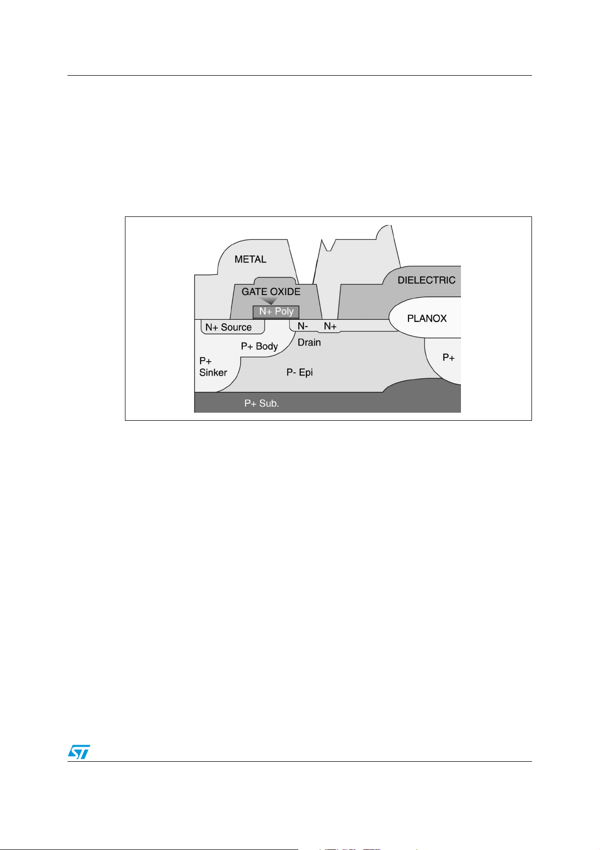
Figure 1. LDMOS structure
In conventional DMOS or bipolar vertical technology, an electrical insulator (Beryllium oxide
or BeO, which is highly toxic), is required to isolate the drain from the ground. In an LDMOS
structure where both the N+ source and the drain region are on the die surface with a
laterally diffused low resistance P+ sinker connecting the source region to the P+ substrate
and source terminal (Figure 1: LDMOS structure on page 5), this insulator is no longer
needed. This not only means that electrical and thermal performances are greatly improved,
but also that the standard DMOS ceramic package (with BeO) used for 1 W and above
devices can be replaced by a plastic package.
Doc ID 7604 Rev 3 5/20
Page 6
What is the PowerSO-10RF? AN1294
2 What is the PowerSO-10RF?
The PowerSO-10RF is an RF optimized version of PowerSO-10™. It is the first
STMicroelectronics JEDEC approved high-power SMD package and has already been in
production for almost 10 years, mainly for products such as rectifiers, protection diodes,
triacs and power transistors (bipolar, MOSFETs and IGBTs), which have already proven
their reliability in automotive, telecom and computer applications where reliability standards
are very high.
2.1 Brief overview of the PowerSO-10RF technology
Figure 2. PowerSO-10RF package construction (JEDEC MO-184 standard)
The plastic package of a power chip has four main functions.
● Electrical interconnection between the silicon LDMOS chip and the external circuit.
● Protection from chemically aggressive agents, for long-term reliability.
● Mechanical support to the LDMOS die to make handling easier.
● A thermally conductive path to transfer the heat generated in operation from the silicon
LDMOS die to the ambient or to the heatsink.
The PowerSO-10RF is the result of an optimization between conflicting requirements of
good thermal properties and small dimensions. Its low thermal resistance is the result of a
large copper heat spreader (slug) integrated into the package body, in direct contact with the
silicon LDMOS die.
The metal frame of the device, consisting of the copper slug (Cu/KFC) and the package
leads is known as the leadframe (Cu/CUPROFOR). The leadframes for a number of
individual devices are manufactured in a single continuous strip to simplify handling and
processing.
6/20 Doc ID 7604 Rev 3
Page 7

AN1294 What is the PowerSO-10RF?
After the silicon LDMOS wafer is cut into individual dice; each die is brazed onto the copper
slug using a high melting temperature (> 280° C) tin solder alloy such as Pb97.5Sn1Ag1.5.
The process used to attach the die to the slug is critical in maintaining the thermal
performance of the RF power device. It must produce a uniform, void-free joint between the
silicon LDMOS’ back metallization and the copper slug in order to avoid hot spots in the
active area and, in the long run, thermal fatigue.
After the die is attached, the silicon LDMOS die is connected to the leadframe with Au or Al
wires that are ultrasonically bonded to both the metallization on the chip (Al alloy: AlSiCu)
and to a nickel layer on the leadframe. The diameter of the wire used is chosen according to
the current to be handled using the approximated rule of about 1 mil (25 µm) per Amp.
Molding is the third step of assembly. The leadframe strips are positioned in molding
cavities, which are then pressure-filled with liquid thermosetting epoxy, which after
solidification provides a hard, reliable and cost-effective encapsulation (the molding
compound is Sumitomo Eme 6300HV with a molding temperature of 200 °C +/- 20 °C).
The last major process is to coat the leads with a low melting temperature thin solder alloy
(tin plating: 7 µm min/15 µm max) to provide a "wettable" surface when the device is
soldered to the printed circuit board (PCB).
After singulation (separation of the leadframe strips into individual devices) and lead forming
(bending of the leads into the required shape), the devices are marked and tested before
being packed and shipped.
There are two available lead versions, shown in Figure 3.
● Formed leads for SMD applications and power dissipation (Pdiss.) < 15 W.
● Straight leads for standard RF mounting on heatsink and Pdiss. > 15 W.
Figure 3. PowerSO-10RF straight and formed lead versions
2.2 Delivery information
The PowerSO-10RF is delivered in a tube of 50 pieces. A bulk quantity equals 250 pieces
(available for both lead versions). A tape and reel form of 600 pieces is also available.
Doc ID 7604 Rev 3 7/20
Page 8

Products AN1294
3 Products
The PowerSO-10RF LDMOS family of products (PDxxxxx series) combines the high
linearity and improved thermal performances of STMicroelectronics’ cutting edge LDMOS
technology with the low-cost, high-performance advantages of plastic packages. It is a
perfect solution for high volume portable, mobile and base station applications for which
space and cost are essential factors.
3.1 Benefits
● Balanced weight
● Good coplanarity
● Reliable solder joint
● Good heat conduction
● Junction temperature of 165° C
● Maximum power dissipation of 150 W
● Improved RF performances (operation >1 GHz)
Table 1. Features and benefits of the PowerSO-10RF
Designed with... Benefits to package and product Benefits to customer
Large heat conductive slug Excellent thermal performance
Good solderability
Careful choice of materials +
consideration of hermetic
properties
Compact dimensions coupled
with high current capability
Leadframe designed for low
parasitic inductance
3.2 Segments and applications
● Military communications (HF/VHF)
● VHF-UHF analog and digital PMR (portable, mobile and BTS)
● TV band IV-V (470-860 MHz)
● Cellular BTS: IS-36, IS-54, IS-95, GSM900, GSM1800, PCS1900, W-CDMA etc.
True RF high-power SMD
products for pick & place
assembly
Balanced weight + excellent lead
coplanarity for optimal leads & slug
contact with PCB + solder reflow
quality inspection points
Simple automatic assembly +
high reliability + easy quality
control + compatible with
industry-standard mounting
techniques
Peace of mind + simple
JEDEC standard
sourcing + high component
reliability
Ability to withstand high junction
temperature + extended operating
temperature range
Product ideally suited to
adverse environments
Improved RF performances RF broadband capability
8/20 Doc ID 7604 Rev 3
Page 9

AN1294 LDMOS in PowerSO-10RF/typical RF performances
4 LDMOS in PowerSO-10RF/typical RF performances
Today LDMOS transistors are used successfully in several digital applications such as
cellular base stations, HDTVs, TETRA applications, etc., and have already proven their
advantages when compared to bipolar transistors. Such advantages include:
● higher power gain
● more constant input impedance under varying drive levels
● better IMD performances
● easier biasing
● gain control by varying the DC gate bias voltage
● better thermal behavior
● lower overall system costs
Moreover, LDMOS products in PowerSO-10RF display similar or better performances than
equivalent products in ceramic packages, such as power gain (similar) and thermal
resistance (~10% lower).
Figure 4. PD57045S-E in PowerSO-10RF versus SD57045-01 in ceramic package
-E
Figure 5. Power gain versus output power/ceramic vs. plastic
-E
Doc ID 7604 Rev 3 9/20
Page 10

LDMOS in PowerSO-10RF/typical RF performances AN1294
Note: LDMOS products in PowerSO-10RF straight leads display a slightly better RF power gain
(up to +1.5 dB) than the same products in PowerSO-10RF formed leads.
This is mainly due to the parasitic reactance induced by the physical shape of the lead.
However, this slight loss in gain is greatly overcome by the SMD capability advantages of
the PowerSO-10RF formed leads version.
Figure 6. Power gain versus output power/straight leads vs. formed leads
-E
10/20 Doc ID 7604 Rev 3
Page 11

AN1294 Quality and reliability
5 Quality and reliability
At STMicroelectronics, before a new product and/or technology can be introduced on the
market it must pass several extensive reliability tests in order to meet ST’s internal stringent
quality goals as well as most of the industry quality standards. PowerSO-10RF has
successfully passed the reliability tests described in Ta b le 2 .
Table 2. Description of reliability tests
Test Features Purpose
To detect surface defects such
as poor passivism,
contamination
H.T.B
Biased device at elevated
temperature
T.H.B Biased in presence of steam Metal corrosion detection
Thermal shock and thermal
cycles
Pressure pot and pressure
cooker
Marking permanency
Shock samples placed in liquids at
high, low temperature. Cycle
samples in high, low ambient
temperature
High temperature and pressure
with saturated steam
10 strokes with brush per MIL
standards
To detect cracked die, wire
bond breaking and mechanical
damage to package
To detect electrochemical and
galvanic corrosion
To measure resistance to
solvent
Solderability Verifies the tinning process To detect poor solder joints
Terminal ruggedness Pulls strength of the terminals To detect poor welds
Doc ID 7604 Rev 3 11/20
Page 12

Soldering method AN1294
6 Soldering method
The key points that can affect the reliability of a solder joint are obviously the choice of
soldering method, the heating profile and the type of solder paste. This matter has been
subject to many publications and its detailed discussion is beyond the scope of this report.
However, some guidelines are given here which may assist the user in choosing the most
appropriate soldering method. Manufacturers can generally choose between two methods
of soldering: vapor phase soldering or infrared heating. Each has its own advantages but
each creates thermal stresses in the device. Before discussing the particular requirements
of the PowerSO-10RF package, a brief overview of the main principles of each method is
presented.
6.1 Vapor phase reflow
Vapor phase reflow involves exposing the board to a perfluorocarbon vapor. The vapor
condenses at the board’s surface on areas marked with a special fluorescent dye and the
latent heat emanating from the process melts the solder. This provides stable heating in an
oxygen-free atmosphere, a method that keeps the risk of damage to components low while
guaranteeing reliable solder joints. The disadvantages of this technique are the high cost of
the liquid and the effects of fluorocarbon gases on the environment.
6.2 Infrared heating
In infrared ovens, air or gas, such as nitrogen, is heated in a tunnel. Boards are carried
through the heat on a conveyor belt. Components are heated through a combination of
convection and radiation from the sources. The amount of heat applied to the board can be
adjusted by controlling the heat of the source panels or lamps, the speed of the conveyor
belt or the rate of circulation of the air or gas. This process causes much more thermal
stress to the device than the previous one, as it heats the device completely, whereas vapor
phase reflow applies heat only where it is required. Both infrared and vapor phase reflow
soldering techniques are appropriate for soldering the PowerSO-10RF. Infrared reflow
soldering, however, is the most commonly used method.
6.3 Soldering paste
The choice of solder paste and the application of the right amount of paste in the correct
shape are both critical for producing high yields in surface mounting. The alloy
Sn95.5/Ag4/Cu0.5 (melting point 217° C) is preferred. This alloy exhibits minimal slump and
has excellent print-after-wait performance. This formula provides superior performance on a
variety of surface finishes and leaves behind a clear residue. Key benefits include
exceptional print-to-print consistency and excellent wetting.
6.3.1 Applying the soldering paste
Applying the solder paste with a screening process is the most widely used technique. It is
performed by aligning the board below the screen, by spreading the solder paste onto the
screen and by moving a squeegee (a soft rubber tool) across it to push the paste through to
the board at the appropriate points.
12/20 Doc ID 7604 Rev 3
Page 13

AN1294 Soldering method
The screen itself consists of the screen mesh, the frame that holds the screen mesh aligned
with the board, and the mask. The screen mesh is designed to hold the solder paste in place
until it is squeezed through the mask by the squeegee. The screen mesh count refers to the
number of openings per inch, which is selected according to the size of the solder particles
in the paste used. For screen printing solder paste, the mesh count may vary from 60 to 150
and, in general, the size of the mesh opening should be chosen to be at least three times
the size of the mean particle size in the solder paste. However, if the area of the openings is
too large, there is a risk of the solder paste forming short-circuit bridges. The distance
between the PCB and the screen mesh is called the snap-on. When the squeegee passes
over the screen, the mesh is stretched down to the board and then snapped back to this
distance. The snap-off has to be set correctly to avoid the print being smeared. This
parameter should be specified by the screen printer manufacturer and depends on the size
of the board. The squeegee hardness and angle of attack also affect the results of the
screen printing. The screen and the squeegee should be restored frequently to obtain a
good solder print on the board.
6.4 Placement of parts and drying
The surface mount components should be placed immediately after the solder paste is
applied to the PCB. Some misalignment is permitted because the surface tension of the
molten solder will align the PowerSO-10RF package with the pad layout of the board. The
drying step follows after placement of the components is completed. The entire application
should be baked in an oven for 45 minutes at 50-80° C to evaporate the moisture content of
the solder paste and to minimize flux and solvent bubbling during the reflow solder process.
This reduces the risk of voids, pinholes and poor wetting.
6.5 Avoiding stresses
There are two main stresses to the package during soldering. The first is due to high
pressure caused by trapped moisture prior to soldering. The second is caused by different
thermal expansion coefficients of the materials used in the package.
Usually the melting point of solder exceeds the maximum rating of the device, so if the
device is heated entirely to such temperatures it may be damaged. Therefore, the thermal
stress to which the devices are exposed must be minimized. This is generally achieved by
using the appropriate solder heating profile. However, the correct soldering heating profile
must be determined by experiment for each particular circuit.
Doc ID 7604 Rev 3 13/20
Page 14

Soldering method AN1294
Figure 7. Recommended heat profile/reflow soldering for PSO10RF lead-free
Stress caused by thermal shocks must be avoided by pre-heating the device to around
150-200 °C. The temperature must then be increased to at least 30 °C above the melting
point of the selected solder paste and maintained long enough to allow a proper wetting and
a homogeneous spread of the solder.
However, under no circumstances should the device rating be exceeded (Tpeak = 250 °C).
In case of infrared heating, black surfaces (such as the plastic body of the package) absorb
more heat than light colored surfaces do (such as leads). The difference in temperature
between the case and the leads should be less than 10 °C. Once soldering is completed,
cooling of the device should not be forced as this will induce mechanical stress and potential
failure. Moreover, as the thermal resistance of the solder joint is determined by the thickness
of the applied solder, a thin layer of 2-4 mils, after reflow, is recommended.
14/20 Doc ID 7604 Rev 3
Page 15

AN1294 Mounting recommendations
7 Mounting recommendations
Epoxy-glass PCBs are commonly used as mounting substrate for electronic applications.
However, their poor conductivity (approximately 50 °C/W) make them poorly suited to
surface-mount power applications. Some existing techniques can be applied however to
considerably improve the thermal performance. The simplest way is to design a layout with a
copper area of suitable dimensions on the board, and use this area as a heat spreader.
Measurements have been made using a 1.6 mm (60 mils) thick FR4 board with a copper
layer of 35 microns. The copper area was varied from 3 to 10 cm
was decreased to 25 °C/W for a 6 cm
2
on-board-heatsink. The maximum power dissipation
capability is between 2 and 3 W.
Figure 8. PowerSO-10RF recommended pad layout
2
. The thermal resistance
To allow a higher power dissipation capability on a conventional epoxy-glass PCB, copperfilled through holes positioned under the slug can be used. Several experiments were
carried out with PowerSO-10RF formed leads and the summary is as follows.
A. FR4 PCB - 1.6 mm (60 mils) thick
49 holes with a pitch of 1.8 mm and an internal diameter of 0.3 mm.
PCB thermal resistance < 3.5 °C/W.
B. FR4 PCB - 0.5 mm (20 mils) thick
49 holes with a pitch of 1.8 mm and an internal diameter of 0.3 mm.
PCB thermal resistance < 2.5 °C/W.
The maximum power dissipation capability is between 15 and 20 W.
Doc ID 7604 Rev 3 15/20
Page 16

Mounting recommendations AN1294
Figure 9. PowerSO-10RF recommended pad layout with via holes
A more sophisticated solution is the use of a metal-backed board consisting of a copper (or
Cu alloy) base plate glued with the PCB. By using this type of board, the RF LDMOS device
in PowerSO-10RF straight-leads package can be soldered directly to the copper layer. As
such, the heat generated by this device is directly transferred to the base plate and as a
result the overall thermal resistance is significantly reduced. In this case, the
PowerSO-10RF device and the external heatsink that can be connected to the copper base
plate only limit the maximum power dissipation capability. Therefore, this solution can be
used for all applications where the power dissipation is higher than 15 W.
Figure 10. Mounting on copper base plate
16/20 Doc ID 7604 Rev 3
Page 17

AN1294 Thermal resistance and maximum power dissipation capability
8 Thermal resistance and maximum power dissipation
capability
Ta bl e 3 gives the thermal resistance and the maximum allowed power dissipation for the
LDMOS PD5xxxx family in PowerSO-10RF plastic package with different mounting
configurations.
● Mounting 1: 1.6 mm FR4-PCB/6 cm² copper area beneath the PowerSO-10RF.
PCB-Rth < 25 °C/W.
● Mounting 2: 1.6 mm FR4-PCB/49 holes (1.8 mm pitch/0.3 mm internal diameter)
connected to the heatsink. PCB-Rth < 3.5 °C/W.
● Mounting 3: 0.5 mm FR4-PCB/same configuration as mounting 2. PCB-Rth < 2.5 °C/W
● On heatsink: PowerSO-10RF soldered directly on heatsink.
Note: Calculations are made with a maximum junction temperature of 165 °C and a heatsink
temperature of 70 °C.
Table 3. Thermal resistance and maximum power dissipation
Part
number
(1)
PD54003-E (S) 1.8
PD54008-E (S) 1.3
PD55003-E (S) 3.0
PD55008-E (S) 1.8
PD55015-E (S) 1.3
PD57002-E (S) 20
PD57006-E (S) 5.0
PD57018-E (S) 3.0
PD57030-E (S) 1.8
PD57045-E (S) 1.3
1. Suffix (S) refers to PowerSO-10RF straight-leads version.
RTHj-slug
(max)
Max Pdiss. on
heatsink
°C/W 52.8 W 3.5 W 17.9 W 22.1 W
°C/W 73.1 W 3.6 W 19.8 W 25.0 W
°C/W 31.7 W 3.4 W 14.6 W 17.3 W
°C/W 52.8 W 3.5 W 17.9 W 22.1 W
°C/W 73.1 W 3.6 W 19.8 W 25.0 W
°C/W 4.75 W 2.1 W 4.0 W 4.2 W
°C/W 19 W 3.2 W 11.2 W 12.7 W
°C/W 31.7 W 3.4 W 14.6 W 17.3 W
°C/W 52.8 W 3.5 W 17.9 W 22.1 W
°C/W 73.1 W 3.6 W 19.8 W 25.0 W
Max Pdiss.
mounting 1
Max Pdiss.
mounting 2
Max Pdiss.
mounting 3
Doc ID 7604 Rev 3 17/20
Page 18

Conclusion AN1294
9 Conclusion
The need for RF surface-mount packages with high power capabilities will increase
dramatically as surface-mount technology becomes even more widespread. Power surfacemount packages that can house even larger die and have lower thermal resistances will
become popular. The PowerSO-10RF, the RF optimized version of the PowerSO-10 (the first
ST package to be JEDEC approved) is the best solution and is the next step in
STMicroelectronics’ long-term strategy to reduce component costs and improve
manufacturability for applications up to 2.5 GHz.
18/20 Doc ID 7604 Rev 3
Page 19

AN1294 Revision history
10 Revision history
Table 4. Document revision history
Date Revision Changes
02-Feb-2001 2 Document migration. No content change.
17-Nov-2009 3
Changed Figure 7: Recommended heat profile/reflow soldering
for PSO10RF lead-free on page 14.
Doc ID 7604 Rev 3 19/20
Page 20

AN1294
Please Read Carefully:
Information in this document is provided solely in connection with ST products. STMicroelectronics NV and its subsidiaries (“ST”) reserve the
right to make changes, corrections, modifications or improvements, to this document, and the products and services described herein at any
time, without notice.
All ST products are sold pursuant to ST’s terms and conditions of sale.
Purchasers are solely responsible for the choice, selection and use of the ST products and services described herein, and ST assumes no
liability whatsoever relating to the choice, selection or use of the ST products and services described herein.
No license, express or implied, by estoppel or otherwise, to any intellectual property rights is granted under this document. If any part of this
document refers to any third party products or services it shall not be deemed a license grant by ST for the use of such third party products
or services, or any intellectual property contained therein or considered as a warranty covering the use in any manner whatsoever of such
third party products or services or any intellectual property contained therein.
UNLESS OTHERWISE SET FORTH IN ST’S TERMS AND CONDITIONS OF SALE ST DISCLAIMS ANY EXPRESS OR IMPLIED
WARRANTY WITH RESPECT TO THE USE AND/OR SALE OF ST PRODUCTS INCLUDING WITHOUT LIMITATION IMPLIED
WARRANTIES OF MERCHANTABILITY, FITNESS FOR A PARTICULAR PURPOSE (AND THEIR EQUIVALENTS UNDER THE LAWS
OF ANY JURISDICTION), OR INFRINGEMENT OF ANY PATENT, COPYRIGHT OR OTHER INTELLECTUAL PROPERTY RIGHT.
UNLESS EXPRESSLY APPROVED IN WRITING BY AN AUTHORIZED ST REPRESENTATIVE, ST PRODUCTS ARE NOT
RECOMMENDED, AUTHORIZED OR WARRANTED FOR USE IN MILITARY, AIR CRAFT, SPACE, LIFE SAVING, OR LIFE SUSTAINING
APPLICATIONS, NOR IN PRODUCTS OR SYSTEMS WHERE FAILURE OR MALFUNCTION MAY RESULT IN PERSONAL INJURY,
DEATH, OR SEVERE PROPERTY OR ENVIRONMENTAL DAMAGE. ST PRODUCTS WHICH ARE NOT SPECIFIED AS "AUTOMOTIVE
GRADE" MAY ONLY BE USED IN AUTOMOTIVE APPLICATIONS AT USER’S OWN RISK.
Resale of ST products with provisions different from the statements and/or technical features set forth in this document shall immediately void
any warranty granted by ST for the ST product or service described herein and shall not create or extend in any manner whatsoever, any
liability of ST.
ST and the ST logo are trademarks or registered trademarks of ST in various countries.
Information in this document supersedes and replaces all information previously supplied.
The ST logo is a registered trademark of STMicroelectronics. All other names are the property of their respective owners.
© 2009 STMicroelectronics - All rights reserved
Australia - Belgium - Brazil - Canada - China - Czech Republic - Finland - France - Germany - Hong Kong - India - Israel - Italy - Japan -
STMicroelectronics group of companies
Malaysia - Malta - Morocco - Philippines - Singapore - Spain - Sweden - Switzerland - United Kingdom - United States of America
www.st.com
20/20 Doc ID 7604 Rev 3
 Loading...