

Page 1
AN1278
APPLICATION NOTE
LIN (LOCAL INTERCONNE CT NETWORK) SOLUTIONS
by Microcontroller Division Applications
INTRODUCTION
Many mechanical components in the automotive sector have been replaced or are now being
replaced by intelligent mechatronical systems. A lot of wires are needed to connect these
compone nts. To red uce the amount of wires an d to hand le commu nicati ons betwee n thes e
systems, many car m anufacturer s have created different bus syst ems that are incom patible
with each other.
In order to have a standard sub-bus, car manufacturers in Europe have formed a consortium
to define a new communications standard for the automotive sector. T he new bus, called LIN
bus, was invented to be used in sim ple switchin g applications like c ar seats, d oor loc ks, sun
roofs, rain sensors, mirrors and so on.
The LIN bus is a sub-bus system based on a serial communications protocol. The bus is a
single master / multiple slave bus that uses a single wire to transmit data.
To reduce costs, components can be driven without crystal or ceramic resonators. Time synchronization permits the correct transmission and reception of data. The system is based on a
UART / SCI hardware interface that is common to most microcontrollers.
The bus detects defective nodes in the ne twork. Data chec ksum and pa rity check guarantee
safety and error detection.
As a long-standing partner to the automoti ve industry, STMicroele ctronics offers a comple te
range of LIN silicon products: slave and master LIN micro controllers covering the p rotocol
handler part and LIN transceivers for the physical line interface. For a quick start w ith LIN,
STMicroelectronics supports you with LIN software enabling you to rapidly set up your first LIN
communication and focus on your specific application requirements.
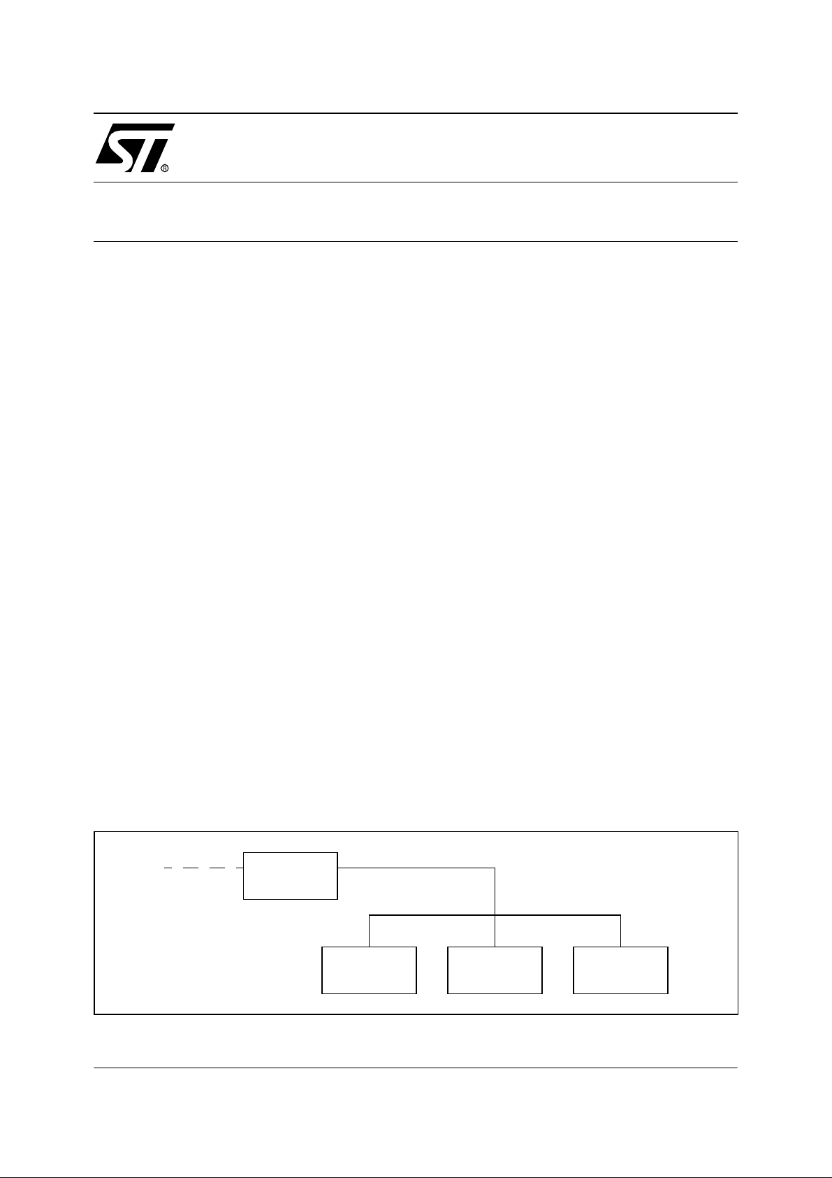
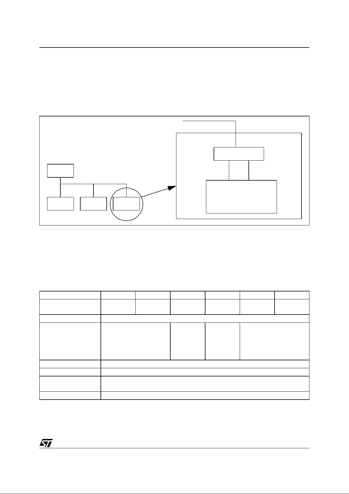
Figure 1. LIN Network Overview
CAN Bus
MASTER
SLAVE
SLAVE
LIN Bus
SLAVE
AN1278/0502 1/44
1
Page 2

Table of Contents
INTRODUCTION . . . . . . . . . . . . . . . . . . . . . . . . . . . . . . . . . . . . . . . . . . . . . . . . . . . . . . . 1
1 LIN PROTOCO L . . . . . . . . . . . . . . . . . . . . . . . . . . . . . . . . . . . . . . . . . . . . . . . . . . . . . . 4
2 LIN PRODUCTS . . . . . . . . . . . . . . . . . . . . . . . . . . . . . . . . . . . . . . . . . . . . . . . . . . . . . . 7
2.1 LIN MICROCONTROLLER S . . . . . . . . . . . . . . . . . . . . . . . . . . . . . . . . . . . . . . . . 7
2.1.1 LIN Slave MCU s . . . . . . . . . . . . . . . . . . . . . . . . . . . . . . . . . . . . . . . . . . . . . 7
2.1.2 LIN Master MCUs . . . . . . . . . . . . . . . . . . . . . . . . . . . . . . . . . . . . . . . . . . . . 8
2.2 LIN TRANSCEIVERS . . . . . . . . . . . . . . . . . . . . . . . . . . . . . . . . . . . . . . . . . . . . . . 9
2.2.1 L9637 K-Line Transceiver . . . . . . . . . . . . . . . . . . . . . . . . . . . . . . . . . . . . . . 9
2.2.2 L9638 LIN Transceiver . . . . . . . . . . . . . . . . . . . . . . . . . . . . . . . . . . . . . . . 10
3 LIN SOFTWAR E . . . . . . . . . . . . . . . . . . . . . . . . . . . . . . . . . . . . . . . . . . . . . . . . . . . . . 12
3.1 TYPES AND MACRO DEFINITIONS: LIB.H . . . . . . . . . . . . . . . . . . . . . . . . . . . 13
3.1.1 Debug settings . . . . . . . . . . . . . . . . . . . . . . . . . . . . . . . . . . . . . . . . . . . . . . 13
3.1.2 Types . . . . . . . . . . . . . . . . . . . . . . . . . . . . . . . . . . . . . . . . . . . . . . . . . . . . . 13
3.1.3 Macros . . . . . . . . . . . . . . . . . . . . . . . . . . . . . . . . . . . . . . . . . . . . . . . . . . . . 13
3.2 PROTOCOL HANDLER: LIN.P/H . . . . . . . . . . . . . . . . . . . . . . . . . . . . . . . . . . . 13
3.2.1 Type definition . . . . . . . . . . . . . . . . . . . . . . . . . . . . . . . . . . . . . . . . . . . . . . 14
3.2.2 User interface functions . . . . . . . . . . . . . . . . . . . . . . . . . . . . . . . . . . . . . . . 14
3.2.3 Timeout handling . . . . . . . . . . . . . . . . . . . . . . . . . . . . . . . . . . . . . . . . . . . . 15
3.2.3.1 Initializing the timer . . . . . . . . . . . . . . . . . . . . . . . . . . . . . . . . . . . 16
3.3 LIN CONFIG URATION FILE: LIN_CONFIG.H . . . . . . . . . . . . . . . . . . . . . . . . . 16
3.4 APPLICATION INTERFACE: LIN_AI.C . . . . . . . . . . . . . . . . . . . . . . . . . . . . . . . 20
4 EXAMPLES . . . . . . . . . . . . . . . . . . . . . . . . . . . . . . . . . . . . . . . . . . . . . . . . . . . . . . . . . 22
4.1 IMPLEMENTATION ON THE ST72254G2 - SOFTWARE EMULA TED SCI . . . 25
4.1.1 Step by Step Configuration . . . . . . . . . . . . . . . . . . . . . . . . . . . . . . . . . . . . 25
4.2 IMPLEMENTATION ON THE S T72334N 4 - HARDWARE SCI . . . . . . . . . . . . . 28
4.2.1 Step by Step Configuration . . . . . . . . . . . . . . . . . . . . . . . . . . . . . . . . . . . . 28
4.2.1.1 lin_config.h . . . . . . . . . . . . . . . . . . . . . . . . . . . . . . . . . . . . . . . . . . 28
4.2.1.2 lin_ai.c . . . . . . . . . . . . . . . . . . . . . . . . . . . . . . . . . . . . . . . . . . . . . 29
4.2.1.3 Master data request (DataRequest_Notification) . . . . . . . . . . . . . 30
4.2.1.4 Data reception (DataReceived_Notification) . . . . . . . . . . . . . . . . 30
4.3 STMICROELECTRONICS LIN PACKAGE - EXAMPLE INSTALLATION . . . . 33
4.3.1 LIN package . . . . . . . . . . . . . . . . . . . . . . . . . . . . . . . . . . . . . . . . . . . . . . . . 33
4.3.2 Quick start with STVD7 and Co smic C Compiler . . . . . . . . . . . . . . . . . . . . 33
4.4 PERFORMANCE . . . . . . . . . . . . . . . . . . . . . . . . . . . . . . . . . . . . . . . . . . . . . . . . 36
4.4.1 Timing considerations . . . . . . . . . . . . . . . . . . . . . . . . . . . . . . . . . . . . . . . . 37
4.4.2 Using the Emulated SCI . . . . . . . . . . . . . . . . . . . . . . . . . . . . . . . . . . . . . . 38
4.4.2.1 Reception . . . . . . . . . . . . . . . . . . . . . . . . . . . . . . . . . . . . . . . . . . . 39
4.4.2.2 Transmission . . . . . . . . . . . . . . . . . . . . . . . . . . . . . . . . . . . . . . . . 40
44
2/44
2
Page 3

Table of Contents
4.4.3 Using the on-chip SCI . . . . . . . . . . . . . . . . . . . . . . . . . . . . . . . . . . . . . . . . 42
4.4.3.1 Reception . . . . . . . . . . . . . . . . . . . . . . . . . . . . . . . . . . . . . . . . . . . 42
4.4.3.2 Transmission . . . . . . . . . . . . . . . . . . . . . . . . . . . . . . . . . . . . . . . . 43
5 SUMMARY OF CHANGES . . . . . . . . . . . . . . . . . . . . . . . . . . . . . . . . . . . . . . . . . . . . . 43
3/44
1
Page 4
LIN (LOCAL INTERCONNECT NETWORK) SOLUTIONS
1 LIN PROTOCOL
The aim of this chapter is to give an overview of the LIN pr otocol and concept. For detail ed and
up-to-date information please ref er to the official LIN hom epage : www.lin-subbus.org where
you can register for the LIN specification package.
The LIN specification package consists of three parts:
■ The LIN protocol specification
■ The LIN configuration language description
■ The LIN API
The first part describes the LIN physical and data link layers. The second part describes the
LIN configuration language. The LIN configuration language enables the user LIN network to
be described in a file (how many nodes, how many frames, frame description, baudrate etc.).
The goal of t his spec ification is t o ea se comm unications be tween the p arties inv olved in the
development of a LIN ne twork like c ar m anu factur ers and the ir suppl iers. The th ird an d l ast
part is abo ut t he sof twa re impl em en tati on of the L IN pro toco l a nd spe cif ies som e po ints on
how the software implementation has to be done.
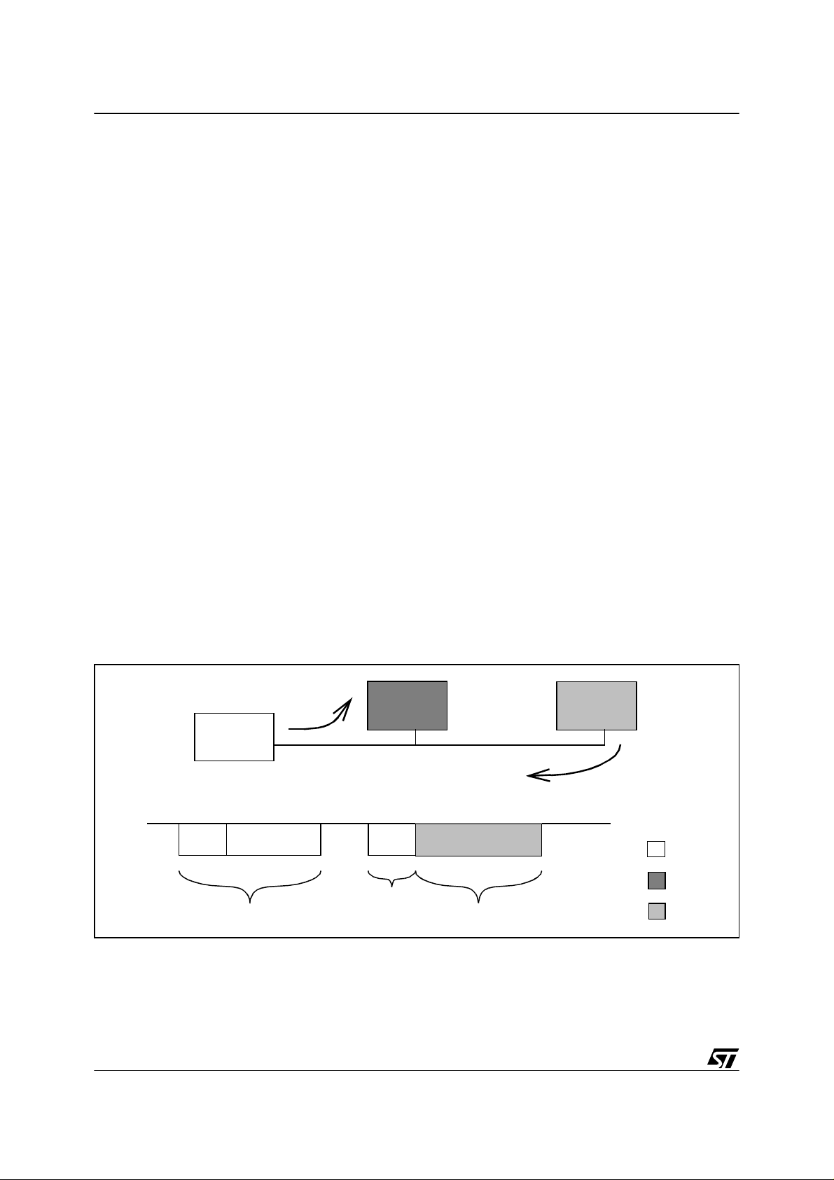
The LIN concept uses a single master / multiple slave model. Only the master is able to initiate
a communication. A LIN frame consists of a header and a response par t. To init iate a c ommunication with a slave the master sends the header part. If the master wants to send data to the
slave it goes on sending the response part. If the master re quests data from the slave the
slave sends the response part.
Figure 2. Basics of LIN communicatio n
Master to slave 1
Slave 1
Slave 2
Master
Slave 2 to master
sent by:
LIN
Bus
Master
Slave 1
1 LIN frame
Header Response
Slave 2
Direct com mu ni cat ion b et wee n sl aves is n ot pos si ble . B ut a s al l n ode s a l way s li sten t o the
bus, a master request can be used to handle slave-to-slave communications.
4/44
Page 5
LIN (LOCAL INTERCONNECT NE TWORK) SOLUTIONS
The LIN protocol is object-oriented and not address-oriented. The header contains the identifier which ident ifies the LI N f rame and t he data i t c onta ins. Diffe rent no des m ay r ecei ve t he
same frame data.
The response part consists mainly of data of selectable length (1 to 8 bytes). The data are secured by an 8 bit checksum.
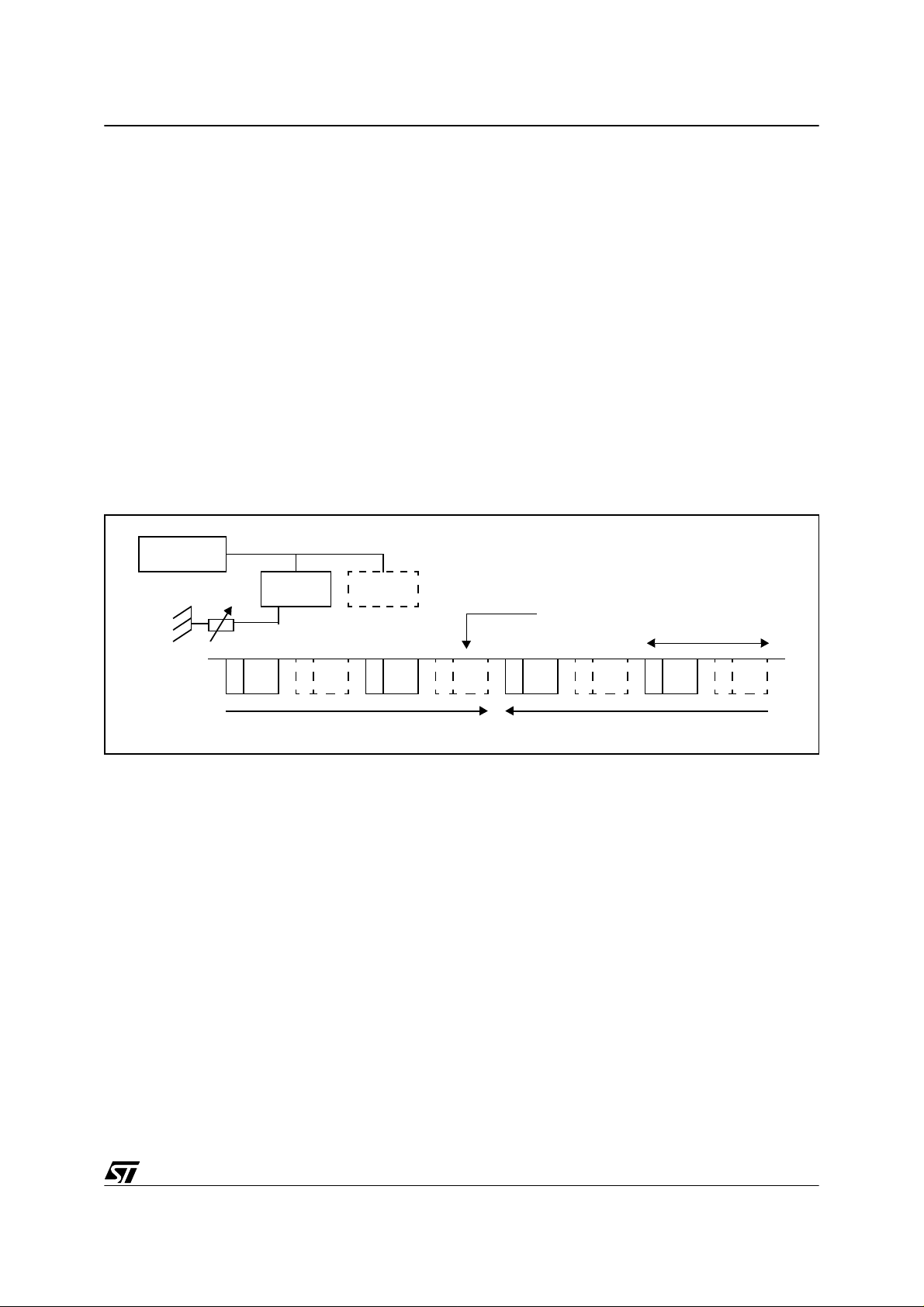
The LIN protocol is time-trigger oriented. The master periodically sends the same sequence of
LIN fram es. Each s equ ence , the m ast er an d the slav es upd ate t he da ta th ey se nd an d receive. The sequence sent by the master may change depending on application events.
Example: The slave is a sensor measuring a analog value which is communicated to the
master via LIN. The slave continuously measures its analog input independently from the LIN
communication. In response to a m aster req uest (periodical) the slave sends the u p-to-date/
last measured value of the analog input.
Figure 3. Time-triggered protocol
Master
Slave 1
Slave 2
Analog
value
1 sequence
change
LIN
Bus
25
Analog value:25
25
38 38
Analog value:38
In order to achieve a good level of security, different mechani sms exist like parity bits on the
identifier or checksum on data bytes.
One important feature of the protocol is to enable the slave MCUs to run with low cost oscillators such as an integrated RC oscillator provided that the accuracy is better than +/-15%. For
this purpose the header contains a sync field byte c onsisting of the constant 0x55. This byte
enables each slave to measure the master bit time and to synchronize its clock accordingly.
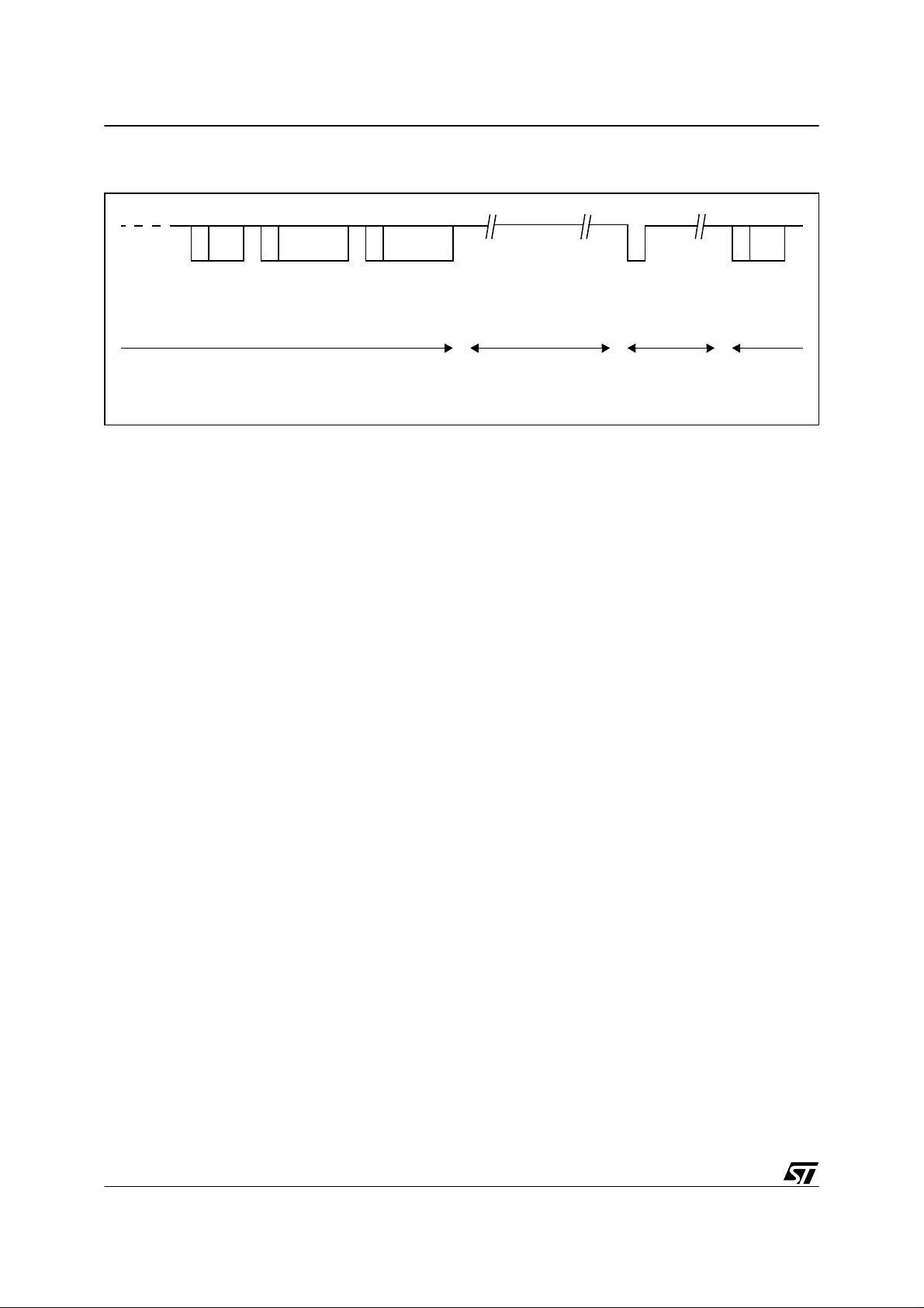
In order to obtain very low power consumption, the master is able to send a sleep frame. Any
node can go into low power mode. To wake up the network, any node can send a so-called
wake-up signal.
5/44
Page 6
LIN (LOCAL INTERCONNECT NETWORK) SOLUTIONS
Figure 4. Sleep mode - wake-up
Sleep mode
command
“normal” mode Sleep mode
Wake-up
signal
Network
start-up
“normal“
mode
6/44
Page 7
LIN (LOCAL INTERCONNECT NE TWORK) SOLUTIONS
2 LIN PRODUCTS
A typical LIN node consists of a microcontroller for handling the LIN protocol and a LIN transceiver for interfacing the digital part and the physical line (see Figure 5 . LIN bus topo logy ).
STMicroelectronics offers both kind of products.
Figure 5. LIN bus topo logy
LIN Bus
TRANSCEIVER
MASTER
LIN Bus
RXTX
MICROCONTROLLER
SLAVE
SLAVE
SLAVE
2.1 LIN MICROCONTROLLERS
STMicroelectronics offers a wide range of microcontrollers suitable for master and/or slave
nodes.
2.1.1 LIN Slave MCUs
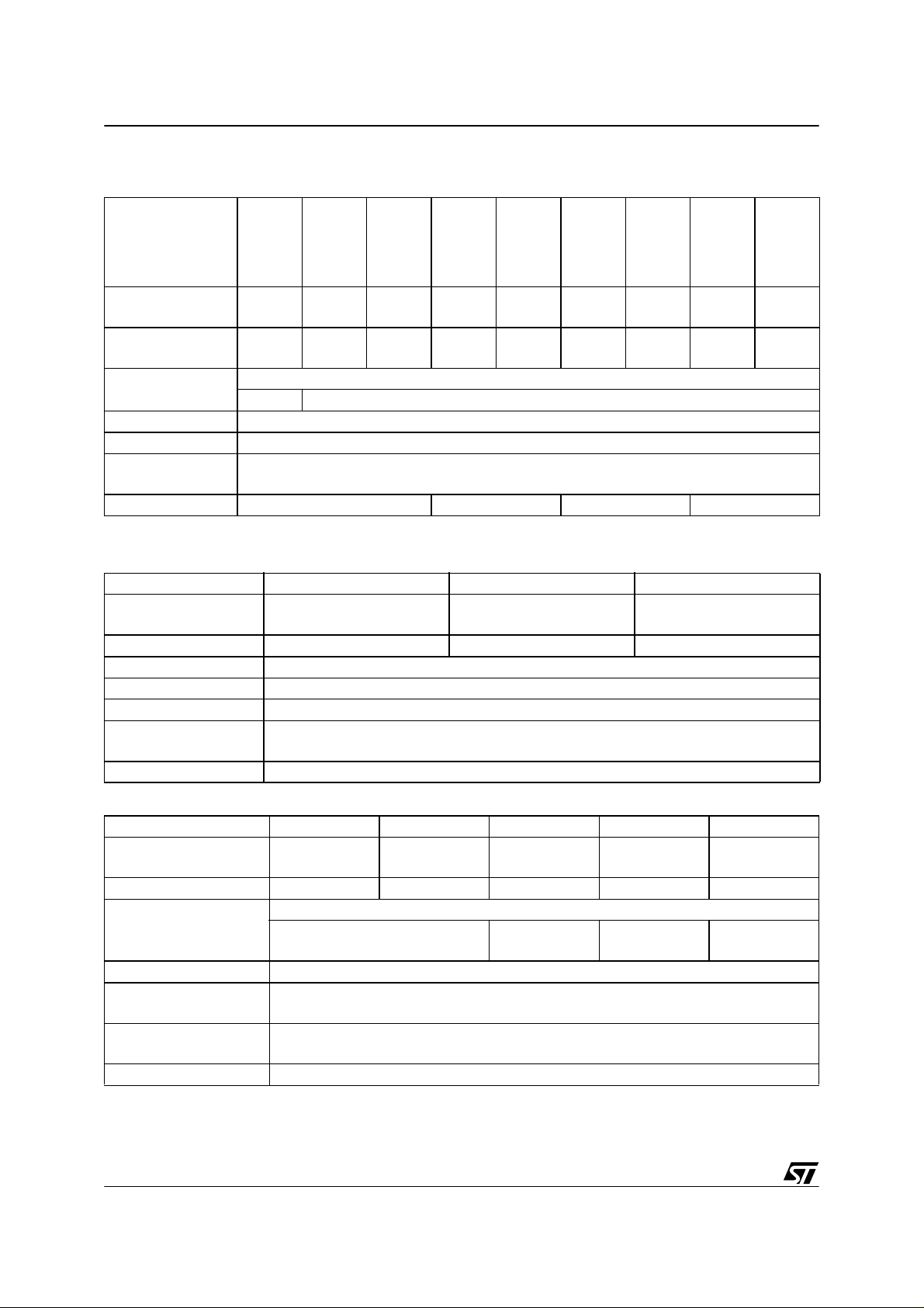
Table 1. Very low cost LIN slave MCUs - full software solution - Flash/ROM MCUs
Features ST72104G1 ST72104G2 ST72216G1 ST72215G2 ST72254G1 ST72254G2
Program memory bytes
RAM (stack) - bytes 256 (128)
Peripherals
Operating Supply 3.2V to 5.5V
CPU Frequency Up to 8MHz (with oscillator up to 16 MHz)
Operating Tempera-
ture
Packages SO28 / SDIP32
4k 8k 4k 8k 4k 8k
Watchdog
timer,
Two16-bit
timers, SPI,
ADC
Watchdog timer, Two 16-
bit timers, SPI, I2C, ADC
Watchdog timer, One 16-
bit timer, SPI
-40°C to +85°C (-40°C to +105/125°C optional)
Watchdog
timer, One
16-bit timer,
SPI, ADC
7/44
Page 8
LIN (LOCAL INTERCONNECT NETWORK) SOLUTIONS
Table 2. Low cost LIN slave MCUs with hardware SCI - Flash/ROM MCUs
Features
ST72124J2
Program memory
- bytes
RAM (stack) -
bytes
Peripherals
Operating Supply 3.0V to 5.5V
CPU Frequency Up to 8MHz (with up to 16MHz oscillator)
Operating Tem-
perature
Packages TQFP44/SDIP42 TQF64/SDIP56 TQF44/SDIP42 TQF64/SDIP56
8k 8k 16k 8k 16k 8k 16k 8k 16k
384
(256)
-ADC
ST72314J2
384
(256)
ST72314J4
512
(256)
Watchdog timer, Two 16-bit timers, SPI, SCI
-40°C to +85°C (-40°C to +105/125°C optional)
ST72314N2
384
(256)
ST72314N4
512
(256)
ST72334J2
384
(256)
ST72334J4
512
(256)
ST72334N2
384
(256)
512
(256)
2.1.2 LIN Master MCUs
Table 3. EPROM/OTP/R OM MCUs
Features ST72511R9 ST72511R7 ST72511R6
Program memory bytes
RAM (stack) - bytes 2048 (256) 1536 (256) 1024 (256)
Peripherals Watchdog timer, Two 16-bit timers, 8-bit PWM ART, SPI, ADC
Operating Supply 3.0V to 5.5V
CPU Frequency Up to 8MHz (with oscillator up to 16 MHz)
Operating Tempera-
ture
Packages TQFP64
60k 48k 32k
-40°C to +85°C (-40°C to +105/125°C optional)
ST72334N4
Table 4. Flash, ROM MCUs (ST7 core)
Features ST72521R/M9 ST 72521R/ M 7 ST72521R/M6 ST72521R5 ST72521R4
Program memory bytes
RAM (stack) - bytes 2048 (256) 1536 (256) 1024 (256) 768 (256) 512 (256)
Peripherals
Operating Supply 2.7V to 5.5V
CPU Frequency
Operating Tempera-
ture
Packages TQFP80(M), TQFP64 (R)
8/44
60k 48k 32k 24k 16k
Watchdog timer, 16-bit timers, SPI, SCI, 10-bit ADC, CAN
8-bit PWM ART, I2C
16 to 50kHz (with 32 to 100kHz oscillator), 500 to 8 MHz (with 1 to 16 MHz oscil-
lator), 2 to 8 MHz (with 2 to 4 MHz oscillator and PLL)
0°C to 70°C/-40°C to +85°C/-40°C to +105°C/-40°C to +125°C/
8-bit PWM
ART
Page 9
LIN (LOCAL INTERCONNECT NE TWORK) SOLUTIONS
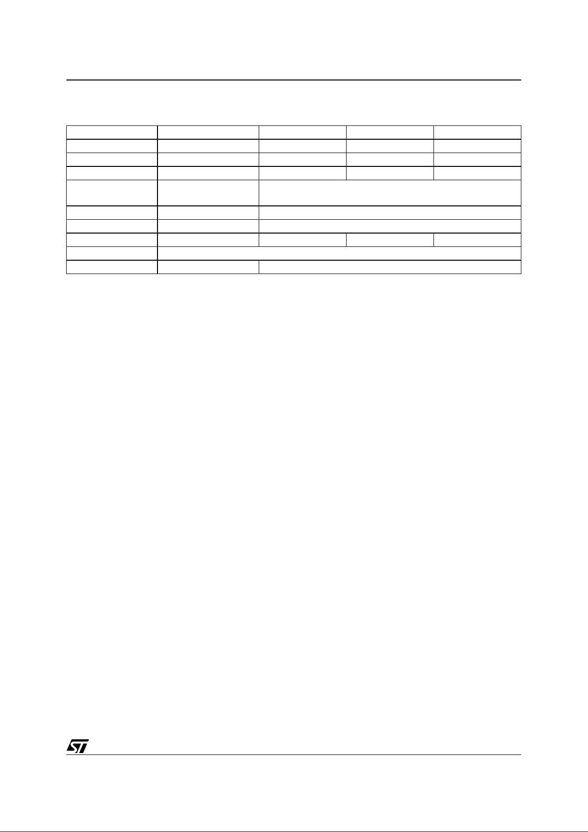
Table 5. Flash, ROM MCUs (ST9 core)
Features ST92F150JD ST92F150JC ST92F124J ST92F124
FLASH - bytes 128K 60/128K 60/128K 60/128K
RAM - bytes 6K 2/4K 2/4K 2/4K
EEPROM - bytes1K 1K1K1K
Timers
2MFT, 2 EFT, STIM,
WD
2MFT, 0/2 EFT, STIM, WD
Serial Interface 2 SCI, SPI, I²C 1/2 SCI, SPI, I²C
ADC 16 x 10 bits 8/16 x 10 bits
Network Interface 2 CAN, J1850 CAN, J1850 J1850 Temp. Range -40°C to 125°C or -40°C to 85°C
Package P/TQFP100 P / TQ FP100 and TQ FP64
Note: The master MCUs listed abov e have all an on-chip CAN peripher al. This corresponds to
the initi al LIN conc ept: t he LI N netw ork a s sub- netw ork of CAN . How eve r any ot her M CUs
(listed above as slave for example) can be used to implement a master node.
2.2 LIN TRANSCEIVER S
To ensure the physical behaviour of the LIN bus STMicroelectronics also offers K-Line dr ivers
and a dedicated LIN Bus Transceiver.
2.2.1 L9637 K-Line Transceiver
The L9637 K-Line transceiver is a monolithic integrated circuit containing standard ISO 9141
compatible interface functions. Its features are listed below.
■ Operating power supply voltage range 4.5V ≤ V
■ Reverse supply battery protected down to V
■ Stand-by mode with very low current consumption IS
■ Low quiescent current in OFF condition IS
■ TTL compatible TX input
■ Bidirectional K-I/O pin with supply voltage dependent input threshold
■ Overtemperature shut down function selec tive to K-I/O pin
■ Wide input and output voltage range -24V ≤ V
■ K output current limitation, typical I
■ Defined OFF output status in under voltage condition and V
■ Controlled output slope for low EMI
= 60mA
K
OFF
≤ 36V (40V for transients )
S
≥ -24V
S
1µA @Vcc 0.5V
SB
= 120µA
≤ V
K
S
or GND interruption
S
■ High input impedance for open V
■ Defined output on status of LO or RX for open LI or K inputs
■ Defined K output off for TX input open
or GND connection
S
9/44
Page 10
LIN (LOCAL INTERCONNECT NETWORK) SOLUTIONS
■ Integrated pull up resistors for TX, RX and LO
■ EMI robustness optimized
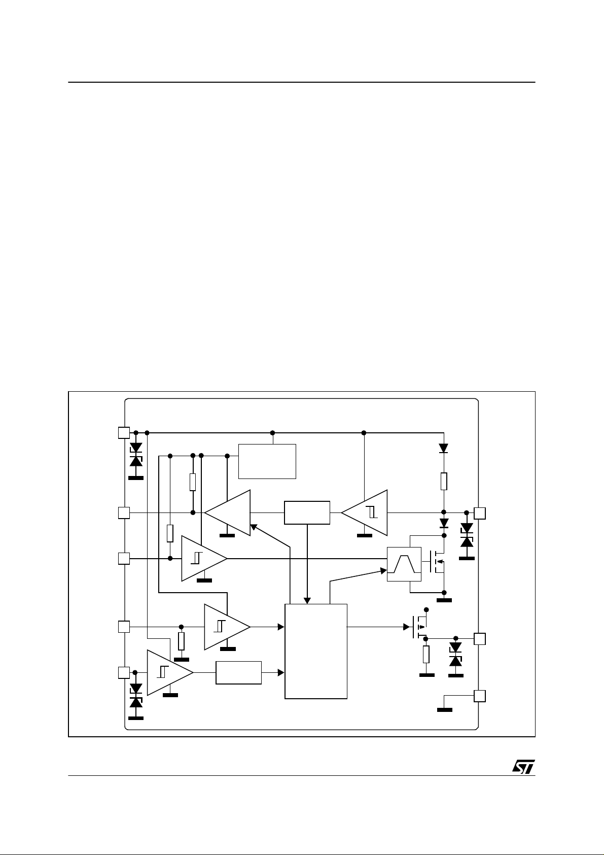
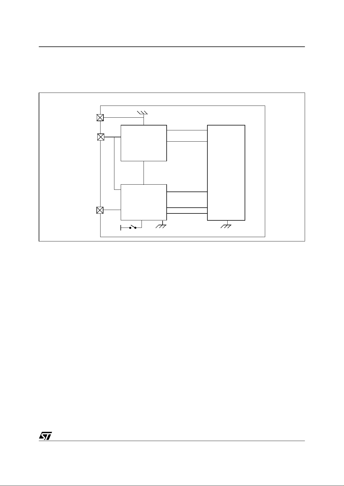
2.2.2 L9638 LIN Transceiver
The L9638 LIN transceiver is a monolithic integrated circuit fulfilling the LIN specification.
Its features are listed below.
■ Wake up capability by:
- LIN bus
- External signal (edge triggered)
■ System wake up functions:
- Inhibit output
- RxD output
■ Quiescent current less than 25µA
■ Fail safe functions implemented
■ Pin compatible to L9637
Figure 6. L9638 block diagram
V
S
Int.5V
RXD
T
D
X
EN
WUP
Glitch
Filter
Internal
Voltage
Regulator
Glitch
Filter
Control
Logic
Protection
LIN
INH
10/44
GND
Page 11
LIN (LOCAL INTERCONNECT NE TWORK) SOLUTIONS
The following figure (Fig ure 7) shows a t ypical applic ation of the L9 638 L IN tran sceiv er together with the ST72124J microcontroller and a voltage regulator.
Figure 7. Application of L9638 with ST72124J Microcontroller
LIN Node
GND
Vbatt
voltage
Vs
regulator
EN
Vout
RES
GND
Vdd
reset
ST72124J
MCU
Vs
INH
EN
I/O pin
LIN
LIN
LIN
Vdd
transceiver
L9638
WUP
TxD
RxD
TDI
RDO
GND
The voltage regulator supplies the application an d generates the MCU reset signal. The LIN
transcei ver is th e physic al line inte rface betw een the SC I (Seria l Com munic ation In terfac e)
TDI and RDO pins of the microcontroller and the LIN bus line. The microcontroller handles the
LIN protocol and the application functions.
In order to lower power co nsumption the microco ntroller is able t o switch o ff the LIN transceiver via the L9638 “EN” input. The transceiver i s then abl e to switch off the voltage regulator
by connecting its “INH” output to the “EN” i nput of the v oltage regulator. In this s tate any activity on the LIN bus wi ll cause the L9638 to wake the voltage r egulator up v ia the “INH” p in.
Another wake-up source is the “W UP” pin of the L9638 that can be used for contact sens ing.
Any edge on this pin will also wake up the regulator.
11/44
Page 12
LIN (LOCAL INTERCONNECT NETWORK) SOLUTIONS
3 LIN SOFTW ARE
Table 6. Software Overview
Version 2.0
Support ed nodes slave
Supported MCUs all ST 7 MC U s
LIN protocol specification revision rev 1.2
The LIN standard includes the specification of the communication protocol but also the use of
associated tools.
STMicroelectronics supp orts the deve lopm ent of y our L IN app lication by prov iding re ady-touse LIN software. This software only handles the communication protocol part. For a complete
software development t ool solution y ou can con tact LIN s pecialist t hird p arty tools ma nufac turers like VCT (http://www.vct.se) or Vector (http://www.vector-informatik.de).
The software supports LIN slave nodes. It consists of 4 files:
– lin.c/h: protocol handler code
– lin_config.c: LIN parameter configuration file
– lin_ai.c: application interface
A fifth additional file is delivered:
– lib.h: library file (macros, types definition)
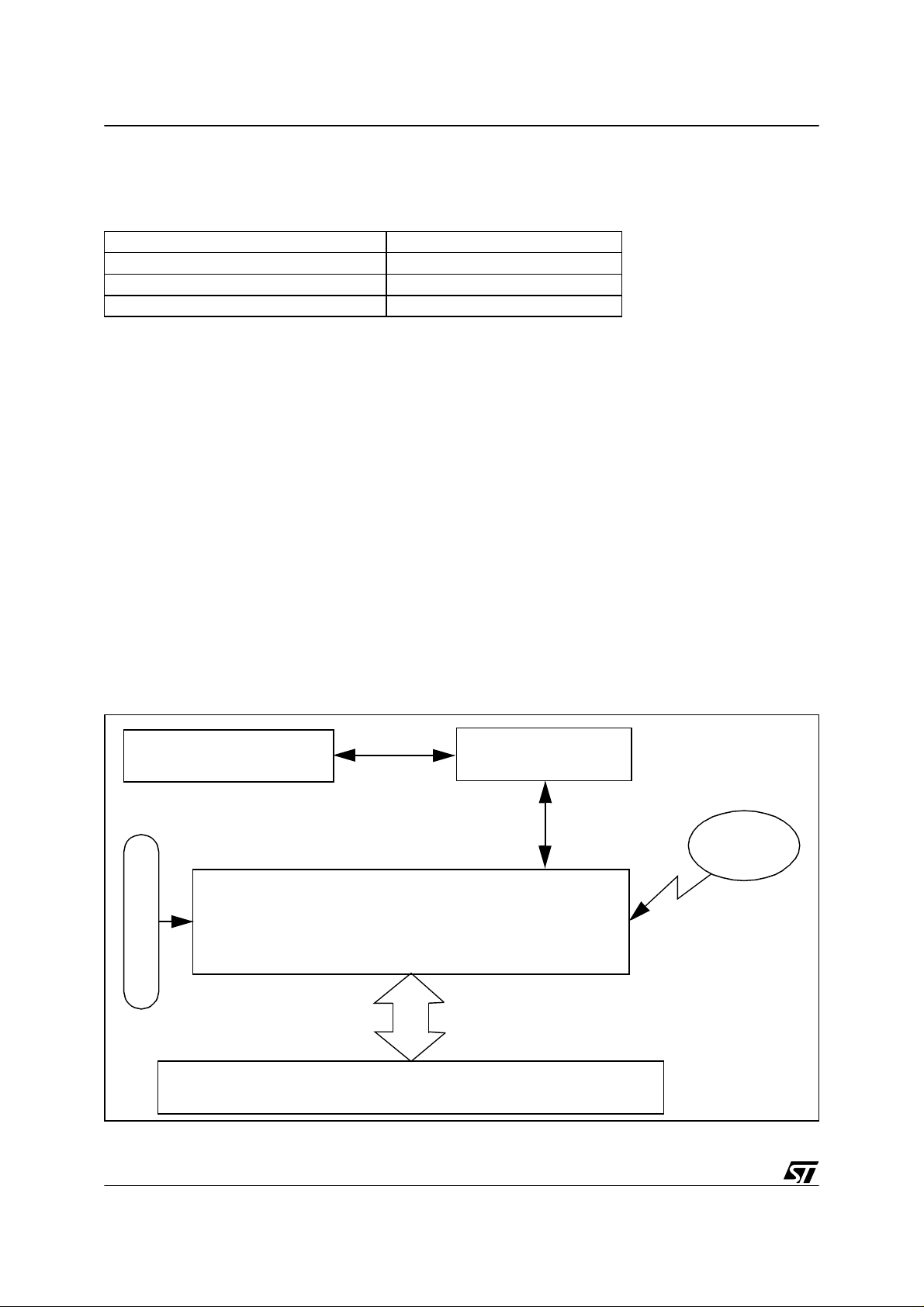
The software supports the COSMIC C comp iler.
Figure 8. Software Architecture
application
APPLICATION
specif ics
lin.c
lin_config.h
lin-ai.c
LIN
MESSAGE
interrupt
12/44
HARDWARE
Page 13

LIN (LOCAL INTERCONNECT NE TWORK) SOLUTIONS
The software is interrupt driven. As soon as a message begins on the bus, an inter rupt is generated and automatically handles the protocol. T his m eans that the protocol handler is totally
autonomous. It runs in the background. When the received frame is decoded by the software
this is notified to the application in the lin_ai.c. In this file the user is able to customize the behaviour of the application upon reception of a frame for example.
3.1 TYPES AND MACRO DEFINITIONS: LIB.H
3.1.1 Debug settings
see 4.4.1 Timing considerations
3.1.2 Types
The software uses predefined types for 1-byte and 2-byte variables.
The name used for the one-byte type is “uByte“.
The name used the two-byte type is “uWord”.
Beside these, a third type is used to define two-byte variables that can also be accessed high
byte or low byte only.
typedef union {
unsigned int w_form;
struct {
unsigned char high, low;
} b_form;
} TwoBytes;
These types are defined in the lib.h file.
3.1.3 Macros
Three macros for register bit access are defined:
– SetBit(var,pos): Set bit “pos” of “var” variable
– ClrBit(var,pos): Clear bit “pos” of “var” variable
– ValBit(var,pos): Test bit “pos” of “var” variable. Return “0” if reset another value otherwise.
3.2 PROTOCOL HANDLER: LIN.P/H
The lin.p file contains the protocol handler. The user has no access to this file. It should simply
be linked to the rest of the application. The lin.p file is encrypted and can therefore not be read
but must be compiled and linked to the rest of the application.
The lin.h con tains th e definition of new typ es and th e protot ypes of th e functions defined in
lin.c.
13/44
Page 14

LIN (LOCAL INTERCONNECT NETWORK) SOLUTIONS
3.2.1 Type definition
t_error
typedef enum {NO_ERROR,BIT_ERROR,ID_PARITY_ERROR,CHECKSUM_ERROR,
NO_ID_MATCH,TIMEOUT_ERROR,DATA_RECEIVED,DATA_REQUEST,
WAKE_UP,UART_ERROR,SYNCH_BREAK_ERROR}t_error;
defines the different error code values that the software functions are able to return.
t_message_direction
typedef enum {ID_DATAREQUEST,ID_DATASENT}t_message_direction;
This type is used internally in lin.c and in lin_drv.c.
t_id_list
typedef struct{
uByte id;
t_message_direction dir;
uByte length;} t_id_list;
defines the type of an identifier list.
t_one_databyte_output
typedef struct{
t_error error_code;
uByte data_byte;} t_one_databyte_output;
defines a type of function return value consisting of an error code made up of error type and a
data byte.
t_header
typedef struct
{
uByte identifier;
uByte length;} t_header;
A LIN frame consists of a header and a response. This typedef defines the header part type.
t_response
typedef struct
{
uByte data[8];
uByte checksum;} t_response;
A LIN frame consists of a header and a response. This typedef defines the response part type.
3.2.2 User interface functions
To integrate this software into your application software you have to l ink 3 or 4 functions defined in lin.c to your project.
14/44
Page 15

LIN (LOCAL INTERCONNECT NE TWORK) SOLUTIONS
Here are the prototypes of these functions:
Function void LIN_Init(void)
Parameters none
Return value none
Description
Function void LIN_SendWakeUpSignal(void)
Parameters none
Return value none
Description
Function void LIN_Interr upt ( vo i d)
Parameters none
Return value none
Description
LIN communication initialization
Has to be called after reset
When the LIN network is in sleep mode and the application
wants to wake it up, this function has to be called to send a
wakeup frame.
LIN interrupt service routine. You should link this function to the
corresponding interrupt vector: timer or SCI interrupt according
to the SCI hardware used (see 3.3 LIN Configuration File:
lin_config.h).
Function void LINTimeOut_Interrupt(void)
Parameters none
Return value none
LIN timeout interrupt service routine (exists only in some cases).
It only exists if SCI is defined or if the timer defined for timeouts
Description
is not the one used for the SCI emulation You should link this
function to the corresponding timer interrupt vector (see 3.2.3
Timeout handling and 3.3 LIN Configuration File: lin_config.h).
3.2.3 Timeout handling
The LIN communication timeout handling is done using one output compare (OC) feature of
the 16 bit timer. If the SC I communication is emulated using a 16 bit timer (uses one OC and
one IC) the user c an and shoul d de fine the sam e timer for both the SC I com municat ion and
the timeout handling. In this case the timer is fully used for the LIN communication and the LIN
software takes full control of the selected timer. If the user decides to configure 2 different
timers for the SCI communication and the timeout handling or if the SCI is not emulated by a
16 bit timer; timeouts are handled using only one OC of a separate timer. In order to leave the
unused OC/IC features free for the application, the application software is responsible for:
15/44
Page 16

LIN (LOCAL INTERCONNECT NETWORK) SOLUTIONS
3.2.3.1 Initializing the timer
The application can initialize the resources that are not used by the L IN software as needed
but is also responsible for initializing the OC defined for the timeouts handling in this way:
OC interrupt
The OCIE flag in Control Register 1 must be set. A write access must be made to the high byte
of th e d ef ine d O u tp ut C om p ar e Re gis ter t o d is ab le t he c or res p on din g in te rru pt sep ar a tel y.
The LIN softw are wi ll enable it when need ed. I f the application is no t us ing the oth er Ou tput
Compare, a write access must be done to the high byte of the corresponding output compare
register to disable the feature.
Timer Clock Initialization
The timer clock/prescaler has to be defined to fulfil the LIN software requirements. The reason
is that the tim eou ts t o be han dled mu s t be sm all er t han a t im er p eri od ot herw is e the o utp ut
compare cannot work properly. The LIN software takes the faster clock that respects this condition. The “prescaler” to be set can be calculated using the following equations. The smallest
value (2,4, or 8) that fulfils the equation is the prescaler value.
Table 7. Equation for prescaler value calculatio n
SCI emulation (FCPU/prescaler/BAUDRATE)*163 < 65536
SCI emulation & resynchr. 1,15*(FCPU/prescaler/BAUDRATE)*163 < 65536
On-chip S C I u se d (FCPU/prescaler/BAUDRATE)*165 < 65536
Timer Interrupt Initialization
The LIN software will use the define OC feature in such a way that an OC interrupt will be generated if a LIN communication timeout occurs. The corresponding timer interrupt has to be defined by the application and the “LINTimeOut_Interrupt” function described above has to be inserted in it. The function checks if the OCxF flag is set and resets it after comp letion.
3.3 LIN CONFIGURATION FILE: LIN_CONFIG.H
The lin_config.h file al lows the user to confi gure the LIN c ommunicat ion. Th e following s ym bols should be set:
#define FCPU
#define FCPU
Description Speed in MHz of the MCU internal frequency
#define UART_TIMERA
#define UART_TIMERB
16/44
Page 17

LIN (LOCAL INTERCONNECT NE TWORK) SOLUTIONS
#define SCI
#define UART_TIMERA, UART_T IMERB or SCI
Description
Define only one
UART_TIMERA or UART_TIMERB if you use a microcontroller without SCI and depending on the timer you want to use. The serial communication will
be emulated by software with a timer. If you use a
microcontroller with an on-chip SCI, define SCI.
The hardware SCI peripheral will be used.
of these options. Define
#define LIN_PORT_ADD
#define LIN_RX_PINNB
#define LIN_PORT_ADD
Needs to be defined only if UART_TIMERA or
UART_TIMERB is defined.
Description
Set which pin is the LIN RX pin. This symbol should
be set to the address of the data register of the I/O
port linked to the LIN RX pin (PC3>set address of
PCDR register).
#define LIN_RX_PINNB
Needs to be defined only if UART_TIMERA or
UART_TIMERB is defined.
Description
Set which pin is the LIN RX pin. This symbol should
be set to the number of the pin linked to the LIN RX
pin (PC3>set 3).
Example: ST72-104/215/216/254 MCU family
SCI emulated by Timer A SCI emulated by Timer B
LIN RX on IC1 LIN RX on IC2 LIN RX on IC1 LIN RX on IC2
LIN RX is pin: PB0 (Port B pin 0) PB2 (Port B pin 2) PC0 (Port C pin 0) PC3 (Port C pin 3)
LIN_PORT_ADD 0x04 0x04 0x00 0x00
LIN_RXC_PINNB 0203
17/44
Page 18

LIN (LOCAL INTERCONNECT NETWORK) SOLUTIONS
#define UART_IC1
#define UART_IC2
#define UART_IC1, UART_IC2
Needs to be defined only if UART_TIMERA or
UART_TIMERB is defined.
Description
Define only one
if the LIN RX pin is connected to the Input Capture
1 pin. Define UART_IC2 if the LIN RX pin is connected to the Input Capture 2 pin.
of these options. Define UART_IC1
#define UART_OC1
#define UART_OC2
#define UART_OC1, UART_OC2
Needs to be defined only if UART_TIMERA or
UART_TIMERB is defined.
Description
Define only one
UART_OC1 if the LIN RX pin is connected to the
Output Compare 1 pin. Define UART_OC2 if the
LIN RX pin is connected to the Output Compare 2
pin.
of these options. Define
#define TIMEOUT_TIMERA
#define TIMEOUT_TIMERB
#defin e TIM EO U T_ T IM ERA, TIM EO U T_ T I MERB
Description
Define only one
er is used for the timeout handling.
If you already defined a timer for the SCI emulation
set the same timer for the timeout handling. This will
optimize the use of resources: A timer is fully used
for the LIN software and the second is free for the
application.
of these options. Define which tim-
#define TIMEOUT_OC1
#define TIMEOUT_OC2
#define TIMEOUT_OC1, TIMEOUT_OC2
Description
Define only one
put compare of the previously defined timer is used
for the timeout handling.
Warning: If the same timer is used for both the SCI
emulation and the timeouts handling, do not define
the same output compare for both features.
of these options. Define which out-
18/44
Page 19

LIN (LOCAL INTERCONNECT NE TWORK) SOLUTIONS
#define BAUDRATE
#define BAUDRATE
Description LIN communication speed in bit/s
#define BRR
#define ExPR
#define BRR, ExPR
Needs to be defined only if SCI is defined.
Set both registers to obtain the baudrate previously
defined. BRR is the “baudrate register” and ExPR
Description
will set the same value for both the “extended receive prescaler division register” and the “extended
transmit prescaler division register”. Refer to the
datasheet of the MCU you are using (“Serial Communication Interface” chapter).
Note: Here is a list of baudr ates and c orresponding s ettings of (BRR,ExPR) depending on the
CPU frequency. Note that there are some small differences in the SCI prescaler between for
example t he ST 723 24/32 1/5 21 an d ST 7 231 4/334 de rivat ive s. A s a re su lt the v alue o f BRR
and ExPR may also depend on the MCU derivative.
Table 8. Example of (BRR,ExPR) values versus baudrate and f
ST72x314/334/124 ST72x324/321/521
f
CPU(*)8MHz4MHz2MHz8MHz4MHz2MHz
bit rate(bit/s)
4,8k
9,6k (0xC9,0x00) (0xC0,0x00) (0x00,0x0D) (0xD2,0x00) (0xC9,0x00) (0xC0,0x00)
19,2k (0xC0,0x00) (0x00,0x0D)
20k (0x00,0x19)
(0xD2,0x00) (0xC9,0x00) (0xC0,0x00) (0xDB,0x00) (0xD2,0x00) (0xC9,0x00)
high quantifi-
cation error
high quantifi-
cation error
high quantifi-
cation error
(0xC9,0x00) (0xC0,0x00)
(0x00,0x19)
CPU
high quantifi-
cation error
high quantifi-
cation error
high quantifi-
cation error
(*): fCPU=fOSC/2 if PLL is not used
#define ID_TABLE_SIZE
#define ID_TABLE_SI ZE
description
number of LIN frames to be handled by the application. See Section 3.4
19/44
Page 20

LIN (LOCAL INTERCONNECT NETWORK) SOLUTIONS
#define RESYNCH
#define RESYNCH
Can only be defined if UART_TIMERA or
UART_TIMERB has been defined.
description
If the application is working with an inaccurate clock
the LIN software is able to resynchronize to the
master clock (refer to the LIN protocol). Define this
symbol to activate this feature.
3.4 APPLICATION INTERFACE: LIN_AI.C
This file is the application interface and should be filled by the user. In this way the user can
define the LIN communication of his application.
The lin_ai.c file consists of:
The ID_Table variable
You fill this variable to define the identifiers of the LIN frames that the application has to
handle.
Each me mber of this list corres pond s to a LIN f ram e and its c orresp onding iden tifier. E ach
member is of type
t_id_list
(See 3.2.1 Ty pe definition) and has to be defined in the fol lowing
way:
identifier, direction, data length
{
}
identifier represents the whole identifier byte including the parity bits.
direction
fore be set to
the application/slave or to
represents the data flow direction, is of type
ID_DATAREQUEST
ID_DATASENT
for data being requested by the master and to be sent by
for data being sent by the master to the application/
t_message_direction
and should there-
slave.
data length
represents the number of data bytes of the corresponding frame. It can be set be-
tween 0 to 8.
Note: The LIN protocol specification gives some advice concerning the coding of the data
length through the ID5 and ID4 bits in the identifier byte. But this coding is no longer mandatory since revision 1.2 of the specification.
The number of members has to be entered in the lin_config.h file (See 3.3 LIN Configuration
File: lin_config.h).
3 Notification functions
The LIN softw are is interrupt driven which means you do not have to poll any variables to
handle LIN c omm uni cati on. When ac tivity a ppe ars on the L IN b us , the LIN i nterrup t s ervice
routine is entered and starts decoding the LIN fr ame. Once the LIN software is able to notify an
20/44
Page 21

LIN (LOCAL INTERCONNECT NE TWORK) SOLUTIONS
event to the application, one of the 3 notification functions is called. These functions are deliv ered empty and by expanding them the user is able to fully define his application LIN communication. The 3 functions correspond to the 3 kinds of events:
Function uByte * DataRequest_Notification(@tiny t_header *header)
Parameters pointer to a variable of type t_header
Return value pointer to an array
This function is called on reception of a LIN header which requests data
i.e. which is defined in the ID_Table with the qualifier
“ID_DATAREQUEST”. The function passes the received header as a
Description
pointer. The user has to complete this function and return a pointer to the
array containing the data to be sent.
Note: The data bytes are buffered by the LIN software just aft er t his function call so that the user does not have to handle data sharing between
the application and the LIN software.
Function
Parameters
Return value none
Description
Function void Error_Notification(t_error error_code)
Parameters variable of type t_error
Return value none
Description
void DataReceived_Notification(@tiny t_header *heade r, @tiny
t_response *response)
pointer to a variable of type t_header, pointer to a variable of type
t_response
This function is called upon the reception of a LIN header and response
which was sent by the master to the application i.e. which is defined in the
ID_Table with the qualifier“ID_DATASENT”. The function passes the received header and response as a pointer. The user has to complete this
function to handle the received data.
This function is called upon the detection of an error. The function passes
the type of error (See t_error t ype defini tion in 3.2.1 Type definition). The
user has to complete this function if special action has to be taken in case
of errors.
21/44
Page 22

LIN (LOCAL INTERCONNECT NETWORK) SOLUTIONS
4 EXAMPLES
The purpose of this chapter is to give you an example, describing step by step how to use the
LIN software. Thi s examp le wa s define d to dem onstr ate the LIN soft ware and not to sh ow a
typical LIN application.
The network consists of the master node and 2 slave nodes.
Figure 9. LIN network example
MASTER
LIN Bus
SLAVE 1
SLAVE 2
The application example is slave1.
The LIN communication consists of 4 LIN frames.
Frame name Identifier ID[7..0] Message Length Data Direction
DataToSlave1 0x03 2 master to slave1
RequestToSlave1 0x20 4 s lave1 to master
RequestToSlave2 0x76 2 s lave2 to master
MasterReq
(sleep mode command)
0x80(*) 2 master to all slaves
(*): The example is given for the LIN specification package 1.1 as many tools stil l don’t support
the 1.2 package.
22/44
Page 23

LIN (LOCAL INTERCONNECT NE TWORK) SOLUTIONS
Figure 10. LIN communication example
master
TX
slave 1
TX
slave 2
TX
bus
line
master
data to
0x03
slave 1
0x03
DataToSlave1 RequestToSlave1 RequestToSlave2
0x20
slave1
data
0x20
0x76
slave2
data
0x76
0x03
0x03
0x20
0x20
The fig ure a bove rep resents th e LIN com munic ation in “r unnin g” m ode . The “Slee pMo deCOmmand” frame is sent by the master to s et the LIN network in sleep mode and is therefore not part of the normal communication.
The baud rate is 9600 baud.
This communication corresponds to the following LIN description file:
23/44
Page 24

LIN (LOCAL INTERCONNECT NETWORK) SOLUTIONS
Figure 11. LIN description file of the example
LIN_description_file ;
LIN_protocol_version = 1.1;
LIN_language_version = 1.1;
LIN_speed = 9.6 kbps;
Nodes {
Master: master, 1 ms, 0.1 ms;
Slaves: slave1, slave2;
}
Signals {
MasterDataToSlave1:16,5,master;
Slave1DataA:16,0,slave1;
Slave1DataB:8,0,slave1;
Slave1DataC:8,0,slave1;
Slave2DataA:8,0,slave2;
Slave2DataB:8,0,slave2;
}
Frames {
DataToSlave1:03,master {
MasterDataToSlave1,0;
}
RequestToSlave1:32,slave1 {
Slave1DataA,0;
Slave1DataB,16;
Slave1DataC,24;
}
RequestToSlave2:54,slave2 {
Slave2DataA,0;
Slave2DataB,8;
}
}
Schedule_tables {
Test_Schedule {
DataToSlave1 delay 10 ms;
RequestToSlave1 delay 15 ms;
RequestToSlave2 delay 15 ms;
}
}
The rest of the example is divided into 2 main parts. The described example is first implemented on the ST72254G2 MCU which has no SCI peripheral. This part demonstrates the capability of the LIN software to emulate the whole LIN protocol using the embedded 16-bit
timer. The second part describes the implementation on the ST72334N4 which has an SCI peripheral.
24/44
Page 25

LIN (LOCAL INTERCONNECT NE TWORK) SOLUTIONS
4.1 IMPLEMENTATION ON THE ST72254G2 - SO FTWARE EMULATED SCI
4.1.1 Step by Step Configuration
lin_config.h
Setting Group Comments Text line in lin_config.h
An external resonator of 16 Mhz
CPU operating frequency
Communication peripheral
LIN RX and LIN TX pin definition
Timeouts
LIN baudrate
is used. As a result the internal
CPU frequency is 8MHz. So
“FCPU” is set to 8000000.
The ST72254 has no SCI peripheral on chip. As a result the
UART communication has to be
emulated by one of the 16bit timer TimerA or TimerB. TimerA is
chosen in this example. As a result “UART_TIMERA” is defined
and “UART_TIMERB” and “SCI”
are commented out.
Depending on the constraints of
the board layout and according to
the ST72254 pinout we select the
Input Capture 1 pin and the Output Compare 1 pin for respectively the LIN RX and LIN TX signals.
The Input Capture 1 pin of TimerA is linked to the Port B pin 0
(see pin description in the MCU
datasheet). As a result
LIN_RX_PINNB” is set to 0. Port
B data register has the address
0x04. As a result
“LIN_PORT_ADD” is defined to
0x04
The UART communication is already using one input capture
and one output compare of TimerA. Setting TimerA for the timeout
handling will complement the use
of the timer. So we define
“TIMEOUT_TIMERA“. Output
Compare 1 is already used by the
UART communication (see
UART_OC1) so we define the
output compare 2 for the timeouts handling.
The example LIN baudrate is
9600 Baud.
#define FCPU 8000000
#define UART_TIMERA
//#define UART_TIMERB
//#define SCI
#define UART_IC1
//#define UART_IC2
#define UART_OC1
//#define UART_OC2
#define LIN_PORT_ADD 0x04
#define LIN_RX_PINNB 0
#define TIMEOUT_TIME RA
//#define TIMEOUT_TIMERB
//#define TIMEOUT_O C1
#define TIMEOUT_O C2
#define BAUDRATE
9600
25/44
Page 26

LIN (LOCAL INTERCONNECT NETWORK) SOLUTIONS
Setting Group Comments Text line in lin_config.h
//#define BRR 0xC9
//#define ExPR 0x00
#define ID_TABLE_SIZE
3
//#define RESYNCH
SCI peripheral registers
Number of LIN frames to be handled
Resynchronization
An SCI peripheral is not used. As
a result “BRR” and “ExPR” are
commented out.
The network communication consists of 4 LIN frames. The application example handles 3 of
them: DataToSlave1,
RequestToSlave1 and SleepModeCommand.
The application is working with a
accurate clock (<2%). The resynchronisation feature is not needed. “RESYNCH” is commented
out.
lin_ai.c
The first part of the lin_ai.c code is the definition of the LIN frames the application has to
handle. Out of the 4 defined for the whole network the application handles the 3 following
frames:
Frame name Identifier ID[7..0] M essag e Len gth Data Direction
DataToSlave1 0x03 2 master to slave1
RequestToSlave1 0x20 4 s lave1 to master
SleepModeCommand 0x80 2 master to all slaves
The corresponding setting of “
const t_id_list ID_Table[]=
{
{0x03, ID_DATASENT, 2},
{0x20, ID_DATAREQUEST, 4},
{0x80, ID_DATASENT, 8}
};
ID_Table
” is:
The second part of the lin_ai.c code consists of 3 notification functions and is the kernel of the
LIN communication. Filling the notification functions enables you to defi ne the behaviour of the
application upon a master data request (
of data from the master (
(
Error_Notification
function).
Master data request (
DataReceived_N otification
DataRequest_Notification
DataRequest_Notification
function) and when errors occur
)
function) on the reception
The application handles one data request from the master corresponding to the identifier 0x20
ID_Table
(
sent. In this example we declare an array “
[1]). The application has to return a pointer to an array containing the data to be
slave_data[]
”. This array will be shared between the
26/44
Page 27

LIN (LOCAL INTERCONNECT NE TWORK) SOLUTIONS
application updating it with the latest data and the LIN communication sending its content on
request of the master. The corresponding code for the “
extern uByte slave_data[];
uByte * DataRequest_Notification(@tiny t_header *header)
{
if(header->identifier == ID_Table[1].id){
return(slave_data);
}
}
DataRequest_Notification
” function is:
Data reception (
DataReceived_Notification
)
The application handles 2 “data” frames from the master corresponding to the identifier 0x03
and 0x80. The first frame is part of the “normal” communication. The second frame is a sleep
command frame that can be sent by the master at any time to interrupt normal communication
and set all nodes into low power mode.
On recepti on of the first fra me the app lication save s the receiv ed data into the variable
master_data[]
“
“.
On reception of the sleep command frame the application sets the ST7 in Halt mode. Before
setting the ST7 in Halt mode the wake-up sources should be acitivated. An application function, “PORTS_WakeUp_On()“, is called. Two pins are configured as interrupt and will wake
the ST7 up on a corresponding interrupt request. The first pin is the Laniards pin. As a result
any bus activity will wake the application up. The second is an application pin that should be
also able to wake up the application.
The corresponding code for the “
extern uByte master_data[];
void DataReceived_Notification(@tiny t_header *header, @tiny t_response *response)
{
if(header->identifier == ID_Table[0].id){
master_data[0]=response->data[0];
master_data[1]=response->data[1];
}
else if(header->identifier == ID_Table[2].id){
PORTS_WakeUp_On();
_asm("halt\n");
}
}
DataReceived_Notification
” function is:
Any activity on the bus will wake up the ST7 out of Halt mode. As soon as the ST7 is ready to
execute the next instruction any incoming frame can be received.
27/44
Page 28

LIN (LOCAL INTERCONNECT NETWORK) SOLUTIONS
The application can also be woken up by a sensor connected to one pin of the ST7 and then
should also wake up the whole LIN network. For this a wake-up frame has to be s ent, which is
done by the “
LIN_SendWakeUpSignal()
” function. This function is therefore inserted in the ap-
plication wake-up interrupt:
@interrupt void PORTS_0_Interrupt(void)
{
unsigned char i;
i=250;
while(i--);
if(!(PADR&0xFE))
{
PAOR&=0xFE;
LIN_SendWakeUpSignal();
}
}
The software is ready!
4.2 IMPLEMENTATION ON THE ST72334N4 - HARDWARE SCI
4.2.1 Step by Step Configuration
4.2.1.1 lin_config.h
Setting group Comments Text line in lin_config.h
An external 16 MHz resonator is
CPU operating frequency
Communication peripheral
LIN RX and LIN TX pin definitions
used. As a result the internal
CPU frequency is 8 MHz. So
“FCPU” is set to 8000000.
The ST72334N4 has an on chip
SCI peripheral. As a result “SCI”
is defined, “UART_TIMERA” and
“UART_TIMERB” are commented out.
These are not needed when using an on-chip SCI peripheral. All
symbols are commented out.
#define FCPU 8000000
//#define UART_TIMERA
//#define UART_TIMERB
#define SCI
//#define UART_IC1
//#define UART_IC2
//#define UART_OC1
//#define UART_OC2
//#define LIN_PORT_ADD
0x04
//#define LIN_RX_PINNB 0
28/44
Page 29

LIN (LOCAL INTERCONNECT NE TWORK) SOLUTIONS
Timeouts
LIN baudrate
SCI peripheral registers
Number of LIN frames to be handled
Resynchronization
4.2.1.2 lin_ai.c
One output compare of one timer
is needed for the timeouts handling. We choose the output compare 1 of timer A. So
“TIMEOUT_TIMERA” and
“TIMEOUT_OC1” are defined.
The example LIN baudrate is
9600 Baud.
See Table 8. Example of
(BRR,ExPR) values versus
baudrate and fCPU.
The network communication consists of 4 LIN frames. The application example handles 3 of
them: DataToSlave1,
RequestToSlave1 and SleepModeCommand.
Not supported using the on-chip
SCI peripheral. “RESYNCH” is
commented out.
#define TIMEOUT_TIME RA
//#define TIMEOUT_TIMERB
#define TIMEOUT_O C1
//#define TIMEOUT_O C2
#define BAUDRATE
9600
//#define BRR 0xC9
//#define ExPR 0x00
#define ID_TABLE_SIZE
3
//#define RESYNCH
The first part of the lin_ai.c code is the definition of the LIN frames the application has to
handle. Out of the 4 defined for the whole network the application handles the 3 following
frames:
Frame name Identifier ID[7..0] M essag e Len gth Data Direction
DataToSlave1 0x03 2 master to slave1
RequestToSlave1 0x20 4 s lave1 to master
SleepModeCommand 0x80 2 master to all slaves
The corresponding setting of “
const t_id_list ID_Table[]=
{
{0x03, ID_DATASENT, 2},
{0x20, ID_DATAREQUEST, 4},
{0x80, ID_DATASENT, 8}
};
ID_Table
” is:
The second part of the lin_ai.c code consists of 3 notification functions and is the kernel of the
LIN communication. Filling the notification functions enables you to defi ne the behaviour of the
application upon a master data request (
tion o f data from th e mast er (
(
Error_Notification
function).
DataReceived_Notification
DataRequest_Notification
function) and upon errors
function) upon the recep-
29/44
Page 30

LIN (LOCAL INTERCONNECT NETWORK) SOLUTIONS
4.2.1.3 Master data request (
DataRequest_Notification
)
The application handles one data request from the master corresponding to the identifier 0x20
ID_Table
(
sent. In this example we declare an array “
[1]). The application has to return a pointer to an array containing the data to be
slave_data[]
”. This array will be shared between the
application updating it w ith the last d ata an d the LIN commun ication s ending i ts contents on
request of the master. The corresponding code for the “
extern uByte slave_data[];
uByte * DataRequest_Notification(@tiny t_header *header)
{
if(header->identifier == ID_Table[1].id){
return(slave_data);
}
}
4.2.1.4 Data reception (
DataReceived_Notification
DataRequest_Notification
)
” function is:
The application handles 2 “data” frames from the master corresponding to the identifier 0x03
and 0x80. The first frame is part of the “normal” communication. The second frame is a sleep
command frame that can be sent by the master at any time to interrupt the normal communication and set all nodes into low power mode.
On recepti on of the first fra me the app lication save s the receiv ed data into the variable
master_data[]
“
“.
On reception of the sleep command frame the application sets the ST7 in Halt mode. Before
setting the ST7 in Halt mode the wake-up sources should be acitivated. An application function, “PORTS_WakeUp_On()“, is called. Two pins are configured as interrupt and will wake
the ST7 up upon a corresponding interrupt request. The first pin is connected to the LIN _RX
pin (the SCI RX pin has no interrupt capability). As a result any bus activity will wake the application up. The second is an application pin that should be also able to wake up the application.
The corresponding code for the “
DataReceived_Notification
” function is:
Any activity on the bus will wake up the ST7 out of Halt mode. As soon as the ST7 is ready to
execute the next instruction any incoming frame can be received.
The application can also be woken up by a sensor connected to one pin of the ST7 and then
should also wake up the whole LIN network. To do this, a wake-up frame has to be sent, which
is done by the “
LIN_SendWakeUpSignal()
” function. This function is therefore inserted in the
application wake-up interrupt routine:
The last point t o be c onf igured is t he ti me out hand l ing and the s ettin g of th e co rres pondi ng
timer, which is timer A. The application software is not using timer A for other purposes. As de-
30/44
Page 31

LIN (LOCAL INTERCONNECT NE TWORK) SOLUTIONS
extern uByte master_data[];
void DataReceived_Notification(@tiny t_header *header, @tiny t_response *response)
{
if(header->identifier == ID_Table[0].id){
master_data[0]=response->data[0];
master_data[1]=response->data[1];
}
else if(header->identifier == ID_Table[2].id){
PORTS_WakeUp_On();
_asm("halt\n");
}
}
@interrupt void PORTS_0_Interrupt(void)
{
unsigned char i;
i=250;
while(i--);
if(!(PADR&0xFE))
{
PAOR&=0xFE;
LIN_SendWakeUpSignal();
}
}
scribed in 3.2.2 User interface functions the application is responsible for the initialization and
the interrupt routine.
Initialization:
Firstly, the output compare must be configured: The OCIE flag of the TACR1 register must be
set and the defined OC disabled by writing the high byte of the OC1 register. As the application is not using OC2 it is disabled also in the same way.
Secondly, the timer prescaler must be calculated using the equations given in Table 7:
on-chip SCI used (FCPU/ prescal er/BAUDRATE)*165 < 65536
1st test: prescaler=2
(FCPU/prescaler/BAUDRATE)*165= 8000000/2/9600*165=68750 > 65536 doesn’t match
1st test: prescaler=4
(FCPU/prescaler/BAUDRATE)*165= 8000000/4/9600*165=34375 < 65536 match!
The prescaler has to be s et to 4 which corresponds to wr iting the value ( 0,0) in the (CC0,CC1)
bits in Timer A Control Register 2.
31/44
Page 32

LIN (LOCAL INTERCONNECT NETWORK) SOLUTIONS
The corresponding initialization code is:
/*-----------------------------------------------------------------------------ROUTINE NAME : TIMA_Init
INPUT/OUTPUT : None
DESCRIPTION : Configure the Timer A
COMMENTS :
------------------------------------------------------------------------------*/
void TIMA_Init(void)
{
TACR1=0x40;
TACR2=0x00;
TASR;
TAOC2_L;
TAOC2_H=0x55;
TASR;
TAOC1_L;
TAOC1_H=0x55;
}
/* -output compare interrupt enabled */
/* prescaler = 4 */
/* erase OC2F flag and */
/* and disable it */
/* erase OC1F flag and */
/* and disable it */
Interrupt:
The time r is o nly us ed fo r th e time out handli ng s o the “LIN Time Out_ Inte rru pt” fun ctio n jus t
needs to be called in the Timer A interrupt service routine defined by the appl ication which corresponds to the following code:
void LINTimeOut_Interrupt(void);
/*-----------------------------------------------------------------------------ROUTINE NAME : TIMA_Interrupt
INPUT/OUTPUT : None
DESCRIPTION : timer Interrupt Service Routine
COMMENTS :
------------------------------------------------------------------------------*/
@interrupt void TIMA_Interrupt(void)
{
LINTimeOut_Interrupt();
}
32/44
Page 33

LIN (LOCAL INTERCONNECT NE TWORK) SOLUTIONS
The software is ready!
4.3 STMICROELECTRONICS LIN PACKAGE - EXAMPLE INSTALLATION
4.3.1 LIN package
The LIN software is delivered in a package including the software itself, this application note
and the above examples for the ST72254 and the ST72334 MCUs .
Figure 12. STMicroelectronics LIN package
st_lin
an
examples
254
application note
ST72254 MCU example
334
lin_v2.0
ST72334 MCU example
LIN software revision 2.0
You will receive a “zip” file called st_lin.zip that will generate the above directory tree. Create
a new folder we will call the working directory and extract the files into it.
The directory tree and architecture are the same for both example.
Figure 13. Example directory tree
254 (resp.334)
config
object
sources
lin
st7
configuration files
(makefile, linker file,
LIN description file)
files generated by compiler
main file
LIN software
ST7 hardware register
declaration
4.3.2 Quick start with STVD7 and Cosmic C Compiler
In order to make the examples run you need the following software to be installed:
-STVD7: STMicroelectronics visual debugger for the ST7 microcontroller family with integrated editing and environment features. This software is free of charge. You can download it
by accessing the STMicroelectronics MCU homepage: mcu.st.com
33/44
Page 34

LIN (LOCAL INTERCONNECT NETWORK) SOLUTIONS
– Cosmic C Compiler: Cosmic C compiler for the ST7 target. F or further inform a tion or con-
tacts go to: http://www.cosmic-software.com/
In order to be able to compile and start a debug session and even flash an ST7 MCU with the
example code you need to create a new STVD7 workspace and configure your COSMIC tools
installation directory.
– Create a new STVD7 project:
start the STVD7 software.
First check that the C osmic com piler installation directory is c onfigured: “Pr oject>Toolchains
Path...” Under “Cosmic Builder Path” enter (if not already configured) the compiler path (where
cxst7.exe is l o ca te d).
We are ready to c reate a n ew proj ect. Select File>N ew W orks pace. U nder “ Work space
filename” enter “334env” (or “254env”). Under “Workspace location” enter the examples directories: <you r working directory>\st_lin\examples\334 (or <your working directory>\st_lin\examples\254). Click on “Next“. Fill in the next dialog box as follows:
Figure 14. Project configuration
or
object\254env.elf
Click “ OK“.
To have easy access to your source files, configure the source file directories in the work-
space window. The example has 3 folders containing the source files:
34/44
Page 35

LIN (LOCAL INTERCONNECT NE TWORK) SOLUTIONS
<your working directory>\st_lin\examples\334\sources\ (or -\254\sources)
main file location (application code location)
<your working directory>\st_lin\examples\334\sources\lin (or -\254\sources\lin)
LIN software location
<your working directory>\st_lin\examples\334\sources\st7 (or -\254\sources\st7)
hardware register declaration
The workspace window should look like this:
Figure 15. Workspace window configuration
The workspace is ready. Save it in the working directory: File>Save Workspace
-Cosmic installation path
The examples are delivered w ith all necessary configuration files like makefiles and linker
files. As far as possible paths are given that are relative to the working directory so you don’t
35/44
Page 36

LIN (LOCAL INTERCONNECT NETWORK) SOLUTIONS
need to update them when you move the example to another directory/PC. One file contains
absolute paths: The linker file located in <your working directory>\st_lin\examples\334\config
(or -\254\config) and named 334env.lkf (resp. 254env.lkf). You need to enter 3 paths. Edit the
file. See Figure 16:
Figure 16. COSMIC linker file configuration
...
+seg .share -a UZPAGE -is -sRAM
<ENTER COSMIC INSTALL PATH>\lib\crtsx.st7 # startup routine
..\object\main.o # application program
..\object\adc.o
..\object\crs.o
..\object\eep.o
..\object\mcc.o
..\object\misc.o
..\object\ports.o
..\object\sci.o
..\object\spi.o
..\object\tima.o
..\object\timb.o
..\object\trap.o
..\object\lin.o
..\object\lin_ai.o
<ENTER COSMIC INSTALL PATH>\lib\libm.st7
<ENTER COSMIC INSTALL PATH>\lib\libims.s t7
+seg .const -b 0xFFE0 -k # vectors start address
..\object\vector.o # interrupt vectors
...
In place of “<ENTER COSMIC INSTALL PATH>” (3 times) enter your Cosmic compiler installation path (path of “cxst7.exe”). For example replace “<ENTER COSMIC INSTALL
PATH>\lib\crtsx.st7” by “c:\cosmic\\lib\crtsx.st7“. Save the file.
The exampl e is ready . You can build th e examp le (F7). B uild will gen erate a 33 4env .elf (or
254env.elf) for debugging and a 334en v.s19 (254env.s19) for flashing an M CU. R efer t o the
STVD7 documentation for details using of the STVD7 editor and debugger.
4.4 PERFORMANCE
The above examples correspond to the 2 main kinds of software configuration, the SCI communicat ion em ulated by sof tware or sup porte d by the har dware SCI pe riph eral. Th e corre -
36/44
Page 37

LIN (LOCAL INTERCONNECT NE TWORK) SOLUTIONS
sponding software performance is different. Table 9 and Table 10 give performance summaries for both examples.
Table 9. ST72254 Example performance summary
Compiler version v4.3a
Memory model +modm - memory short
Compiler options +debug
whole project 2.1 kbyte
Code size
LIN interrupt - CPU load 17%
Max LIN baudrate @16MH z 16kbaud
lin.o 1.8 kbyte
lin_ai.o 44 byte
Table 10. ST72334 Example performance summary
Compiler version v4.3a
Memory model +modms - memory small
Compiler options +debug
whole project 1.4 kbyte
Code size
LIN interrupt - CPU load 2%
Max LIN baudrate @16MH z no limit-20kbaud
lin.o 1.0 kbyte
lin_ai.o 44 byte
4.4.1 Timing considerations
The runtime performance of the software depends on many parameters like the memor y
model, the compiler options and the co mpiler version and also on the application (lin_ai.c is
part of the LIN interrupt). As a result it is impossible to give generally applicable software
runtime performance data.
A first timing consideration is the maximum reachable speed running the software without any
application software. In this case only the software emulating the SCI communication
(ST72254 example) has speed limitations. In the above ST72254 example the maximum
speed reachable was 16kbaud. The software using the on-chip SCI peripheral has no LIN
speed limitation.
Then if you add some application code in the lin_ai.c file, you make the LIN interrupt service
routine longer and there fore decrease the softwar e performance. That’ s why in order to
achieve better performance you should keep actions done in the lin_ai.c file as short as possible. Nevertheless the software that uses the on-chip SCI peripheral should not be speed limited under 20kbaud.
The final timing consideration is when the application software needs to interrupt the LIN communicati on. The LI N softw are is int errupt-d riven a nd betwe en two in terrupt s the ap plication
software can run some other code. As long as the application software is interruptable, the LIN
software will interrupt it when needed. Problems can occ ur if the appli cation software i s not in-
37/44
Page 38

LIN (LOCAL INTERCONNECT NETWORK) SOLUTIONS
0000000000000000000000000000000000000000000000000000000000000000000000000000000000000000000000000000000000
0
00000
0000000000000000000000000000000000000000000000000000000000000000000000000000000000000000000000000000000000
terruptable for a long time so that the LIN interrupt is c alled too late an d an ev ent is lost ( bit/
byte). As too many parameters are involved it’s impossible to give genera lly-applicable performanc e da ta. Th ere fore we imp lem ented a tim ing an alys is fe ature (DEBU G_M OD E) yo u
can activate when debugging your software.
This feature can be activated in the lib.h file using 5 symbols:
#define DEBUG_MODE
When defined, this activates the timing debug fea-
Description
#define
Description
ture. This feature configure an pin as output and
uses it to indicate when the LIN interrupt is entered
(set) and when it is left (reset).
DEBUG_PxDRADD
DEBUG_PxDDRADD
DEBUG_PxOR A DD
To configure the used I/O pin, first define these
symbols to the address of the corresponding data
register, data direction register and option register.
#define DEBUG_LI N_IT_P IN
Description
Set this symbol to the pin number used (ex: 5 when
using PC5)
The final piece of information you need to do the timing analysis is how much can the application delay the occurrence of the LIN interrupt? For this we need to go into more detail to analyze the way the softwar e is handling ea ch bit/by te. Onc e again, dep endin g on whethe r the
SCI communication is emulated or not the software is works in very different ways:
4.4.2 Using the Emulated SCI
Figure 17. SCI emulation: LIN Receptio n
LIN Bus
0000000000000000000000000000000000000000000000000000000000000000000000000000000000000000000000000000
LIN interrupt running
CPU not used for LIN
OC
38/44
ICOC
OC
OC
OC OC
OC
OC
OC OC
Page 39

LIN (LOCAL INTERCONNECT NE TWORK) SOLUTIONS
4.4.2.1 Reception
The SCI is emulated by software using the input capture and output compare of the on-chip
16-bit timer. When the bus is idle, the software waits for a negative edge: The input capture interrupt is activated and calls the LIN i nterrupt when a negative edge occurs. The i nput c apture
time is used to generate an output compare in the middl e of thi s fir st bit. The LIN interrupt r outine returns to the calling program. When the output compare event occurs the LIN interrupt is
called again. The bus level is checked and a new output compare is set to occur in the middle
of the next bit. This last process is repeated until the stop bit.
As a result the application software should not:
– delay the occurrence of the IC interrupt too much. Specifically: A problem occurs if the first
output compare is set after the expected occurrence of the output compare event, which is
the middle of the bit. So as long as the IC interrupt ends before the middle of the bit, the delay
is acceptable. See Figure 18.
Figure 18. IC Interrupt Han din g in Reception Mode
start bit
1/21/2
application task
deadline for
end of IC interrupt
IC request
IC interrupt served
– Delay the occurrence of each OC interrupt too much. Specifically: A problem occurs if the
sample time defined at the beginning of the interrupt is delayed so that it occurs after the end
of the bit. See Figure 19.
39/44
Page 40

LIN (LOCAL INTERCONNECT NETWORK) SOLUTIONS
Figure 19. OC interrupt Han dling in Reception Mode
1 bit
application task
OC request OC interrupt served
4.4.2.2 Transmission
deadline for
start of OC interrupt
For transmission the so ftware only uses th e O utput Com pare feature of the 16-bit time r. For
each bit, two OC interrupts are generated. The fir st one is gener ated to output the v alue of the
new bit. The second is used to read back the bus and check whether the output value is actually being sent, in other words to check for a bit error. See Figure 20.
Figure 20. SCI emulation: LIN Transmission
1 bit
1st OC: 2nd OC:
output new bit read back
The bit transition ti me is precise because the ti mer output compare itself outputs the new l evel
when an out put comp ar e ev en t occu rs. Soft wa re delay s d o not inf luenc e th e bit t rans iti ons.
The first OC sets a new OC for the middle of the bit. The second reads the LIN bus level and
prepares the next OC to output the next bit.
As a result the application software should not:
40/44
Page 41

LIN (LOCAL INTERCONNECT NE TWORK) SOLUTIONS
– Delay the occurrence of the first OC interrupt too much. Specifically: A problem occurs if the
second output compare is set after the expected time, which is the middle of the bit. So as
long as the first OC interrupt ends before the middle of the bit, the delay is acceptable. See
Figure 21.
Figure 21. Handling the first OC Interrupt in transmissio n mode
1 bit
application task
deadline for
end of 1st
OC interrupt
1rst OC request
1rst OC serviced
– Delay the occurrence of the second OC interrupt too much. Specifically: A problem occurs if
the sample time defined at the beginning of the interrupt is delayed outside the bit. See Fig-
ure 22
Figure 22. Handling the second O C Int e rrupt in transmission mode
1 bit
application task
deadline for
start of 2nd
OC interrupt
2nd OC request 2nd OC serviced
41/44
Page 42

LIN (LOCAL INTERCONNECT NETWORK) SOLUTIONS
00000
000000000000000000000000
0
00000
000000000000000000000000
00000
4.4.3 Using the on-chip SCI
Using the on-chip SCI the flexibility is considerably increased. The CPU load is very low and
the capability of the application software to run at the same time as the LIN software is high.
Firstly a LIN i nterrupt occu rs e very by te instea d of ev ery bit (ev en every ha lf bi t in t ransm ission) in the timer solution. And seco ndly the received byte is buffered in hardwar e which allows a lot of flexibility.
Figure 23. CPU load with on-chip SCI peripheral
LIN frame
LIN Bus
LIN interrupt running
CPU not used for LIN
000000000000000000
000000000000000000
000000000000000000
4.4.3.1 Reception
The on-chip peripheral is handling the SCI communication and notifies a reception at the end
of each byte. A LIN interrupt is then generated and handles the received data according to the
LIN protocol.
Figure 24. Reception Notification Interrupt
1 byte
stop
bit
When the SCI notifies the reception it copies at the same time the received value into a buffer.
As a result the peripheral is ready for the next reception and the software can still hold the received data until the end of the new reception. Afterwards an overrun condition occurs.
42/44
SCI reception notification
LIN interrupt
Page 43

LIN (LOCAL INTERCONNECT NE TWORK) SOLUTIONS
As a result the application software should not delay the occurrence of the SCI reception notification interrupt so much that an overrun condition occurs. Specifically: The end the LIN interrupt should end before the stop bit of the next byte.
Figure 25. Reception Interrupt Handling
1 byte
application task
SCI reception
interrupt served
interrupt request
4.4.3.2 Transmission
In transmission delays co ming from the applicatio n cannot disturb the proper w orking of the
software. This will delay the transmission and the issue is more a timeout issue on the current
transmitted frame: If the interrupt time is very long the transmitted frame may exceed the maximum allowed frame time. The SCI interrupt in transmission occurs also at the stop bit. If the
occurrence of the interrupt is delayed by the application the interbyte time will increase.
5 SUMMAR Y OF CHANGES
Revision Main changes Date
1.0 F irst version August 2001
1.1 Remove section “HOW TO GET THE LIN SOFTWARE?” April 2002
43/44
Page 44

LIN (LOCAL INTERCONNECT NETWORK) SOLUTIONS
“THE PRESENT NOTE WHICH IS FOR GUIDANCE ONLY AIMS AT PROVIDING CUSTOMERS WITH INFORMATION
REGARDING THE IR PRO DUCT S IN OR DER FO R THEM TO SAV E TIME . AS A RES ULT, STMIC ROEL ECTR ONI CS
SHALL NOT BE HELD LIABLE FOR ANY DIRECT, INDIRECT OR CONSEQUENTIAL DAMAGES WITH RESPECT TO
ANY CL AIM S AR IS IN G FR OM T HE CO N TENT OF S UC H A NO TE A ND /O R T HE U SE M AD E BY C US TO ME RS O F
THE INFORMATION CONTAINED HEREIN IN CONNECTION WITH THEIR PRODUCTS.”
Information furnished is believed to be accurate and reliable. However, STMicroelectronics assumes no responsibility for the consequences
of use of such information nor for any infringement of patents or other rights of third parties which may result from its use. No license is granted
by implic ation or otherwise under any patent or patent ri ghts of STM i croelectr oni cs. Spec i fications mentioned i n this publication are subje ct
to change without notice. This publication supersedes and replaces all information previously supplied. STMicroelectronics products are not
authorized for use as cri tical comp onents in life support dev i ces or systems wi thout the express written approv al of STMicroel ectronics.
The ST logo is a registered trademark of STMicroelectronics
2002 STMicroelectronics - All Rights Reserved.
STMicroelectronics Group of Compan i es
http://www.s t. com
Purchase of I
2
C Components by STMicroelectronics conveys a license under the Philips I2C Patent. Rights to use the se components in an
2
I
C system i s granted pro vi ded that the sy stem conforms to the I2C Standard Specification as defined by Philips.
Australi a - B razil - Canada - China - Finl and - France - Germany - Hong Kong - Ind ia - Israel - Italy - Japan
Malaysi a - M al ta - Morocco - Singapore - Spain - Sw eden - Switz erland - United Kingdom - U.S.A.
44/44
 Loading...