

AN1220
Obsolete Product(s) - Obsolete Product(s) Obsolete Product(s) - Obsolete Product(s)
®
APPLICATION NOTE
LINECARD PROTECTION BY OVERVOLTAGE
A.S.D
INTRODUCTION
This device includes a primary protection level and is suitable for main distribution frames and line cards.
This protection concept is explained and, in addition, the CLP270M performances are analysed when
facing different surges as described in the BELLCORE GR 1089 recommendations.
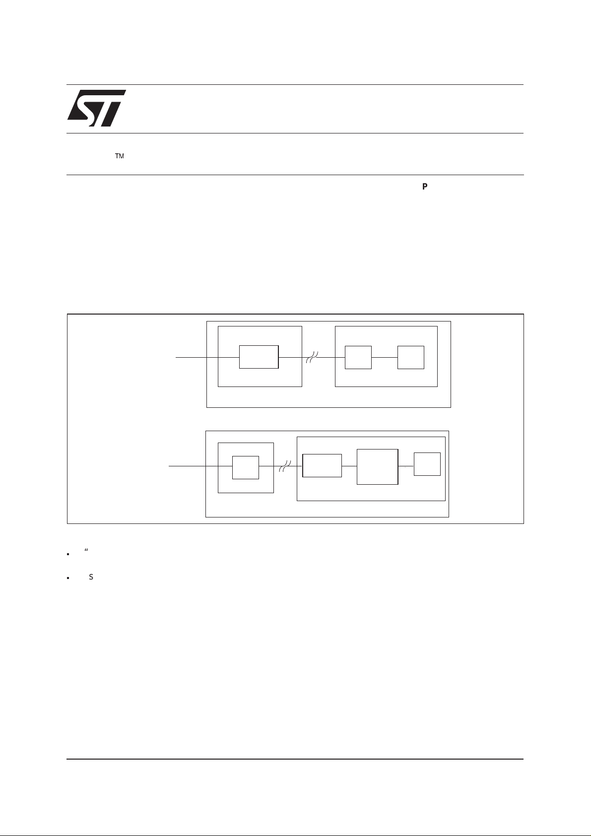
Figure 1 is a simplified block diagram of a subscriber line protection that is commonly used.
Fig. 1: Subscriber line protection topology
ä
Telecommunication
line
AND OVERCURRENT WITH A CLP270M
P.Merceron / A.Bremond
“PRIMARY PRO TECTION”
CLP270M
MDF
EXCHANGE
“SECONDARY PROTECTION”
SLIC
LINE CARD
“SECONDARY PROTECTION”
Telecommunication
line
CLP270M
MDF
EXCHANGE
THDTxx
or
LCP1511D
or
LCDP1511D
LINE CARD
SLIC
This shows two different topologies :
n
A“primaryprotection”locatedontheMainDistributionFrame(MDF) eliminates coarsely the high energy
environmental disturbances (lightning transients and AC power mains disturbances)
n
A “secondary protection” located on the line card includes a primary protection level (first stage) and a
residual protection (second stage) which eliminates finely the remaining transientsthat have not been totally
suppressed by the first stage.
January 2000
1/13
Obsolete Product(s) - Obsolete Product(s) Obsolete Product(s) - Obsolete Product(s)
APPLICATION NOTE
STMICROELECTRONICS CLP270M CONCEPT
1. Evolution of the SLIC protection
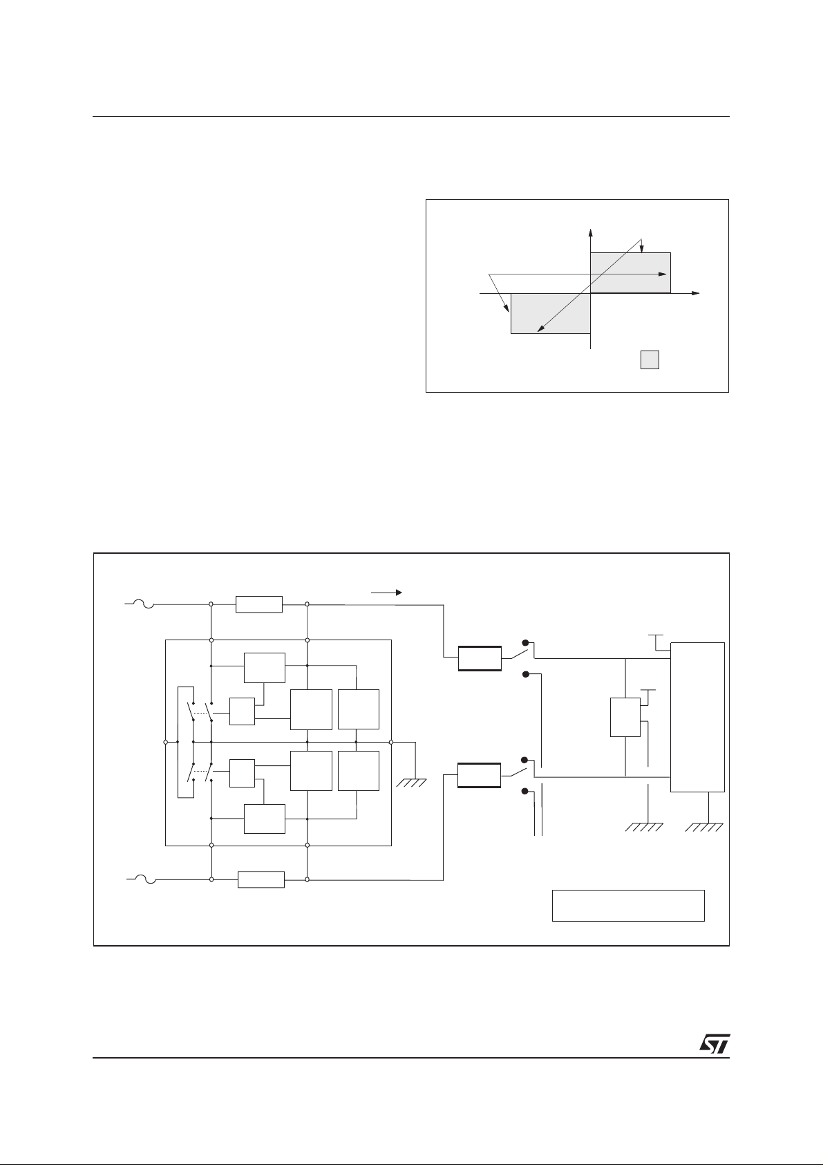
Fig. 2: Line card protection
Over the years, the silicon protection
performances have considerably changed.
The first generation of products like SMTHBTxx
and SMTHDTxx offered fixed overvoltage
protectionagainst surges oneither TIP orRING line
in four packages.
The following generation like THBTxx and
Programmable
thanks to any
external v o ltage
reference
+I
I
SWON
Programmable
thanks to an
external resistor
V
THDTxx still offered fixed overvoltage protection
against surges on both TIP and RING lines in two
packages.
The next step was the introduction of the LCP
devices which brought the advantage of full
programmable voltage.
-I
SWON
Line card
operating
conditions
Today, the CLP270M combines the features of all
the previous generations. In addition to that, it offers an overcurrent detection when operating in speech
mode and also a Failure Status output signal.
The figure 2 summarizes the firing modes of the CLP270M which basically holds the SLIC inside its correct
voltage and current values.
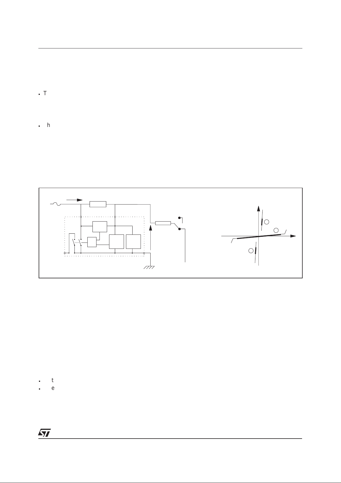
Fig. 3 : CLP270M in line card
er oltage
erence
I
-Vbat
TIP
-Vbat
(*)
SLIC
RING
Rp
Rp
1
2
1
2
External
voltage
reference
Ring
Generator
(*) LCP1511D orTHDT series or LCDP1511D
TIP
RING
Fuse
Rsense
TIPL TIPS
Overcurrent
detector
detector
detector
RINGS
Ov v
ref
(+/- 270V)
Overvoltage
reference
(+/- 270 V)
OR
SW3 SW1
FS GND
Fuse
SW4 SW2
OR
Overcurrent
RINGL
Rsense
Overvoltage
Overvoltage
detector
2/13
Obsolete Product(s) - Obsolete Product(s) Obsolete Product(s) - Obsolete Product(s)
APPLICATION NOTE
2. Application circuit: CLP270M in line card
Figure 3 shows the topology of a protected analog subscriber line at the exchange side. The CLP270M is
connected to the ring relay via two balanced Rp resistors, and to the Subscriber Line Interface Circuit. A
second device is located near the SLIC : it can be either a LCP1511D, a THDT series or a LCDP1511D.
These two devices are complementary and their functions are explained below :
The first stage based on CLP270M manages the high power issued from the external surges. When
n
used in ringing mode, the CLP270M operates in voltage mode and provides a symmetrical and
bidirectional overvoltage protection at +/- 270 V on both TIP and RING lines. When used in speech
mode,the CLP270M operates incurrent mode and the activation current of the CLP270Mis adjusted
sense
.
by R
The second stage is the external voltage reference device which defines the firing threshold voltage
n
during the speech mode and also assumes a residual power overvoltage suppression. This protection
stage can be either a fixed or programmable breakover device. The THDTxx family acts as a fixed
breakover device while the LCP1511D or the LCDP1511D operates as a programmable protection.
Thanks to this topology, the surge current in the line is reduced after the CLP270M. Because the
remaining surge energy is low, the power ratings of Rp, the ring relay contacts and the external voltage
reference circuit can be downsized. This results in a significant cost reduction.
Fig. 4: Switching by voltage during ringing mode.
Fuse
TIP
ILG
Rsense
TIPL TIPS
1/2 CLP270M
Overcurrent
detector
V
Overvoltage
Overvoltage
detector
OR
SW3 SW1
FS
reference
(+/- 270V)
LG
GND
1
Rp
2
-270
I
LG
A1
2
1
+270
3
3. Ringing mode
In ringing mode (Ring relay in position 2), the only protection device involved is the CLP270M.
In normal conditions, the CLP270M operates in region 1 of A1 curve, and is idle.
Ifan overvoltage occuring between TIP (or RING)and GND reaches theinternal overvoltage reference
(+/- 270 V), the CLP270M acts and the line is short-circuited to GND. At this time the operating point
moves to region 2 for positive surges (region 3 for negativesurges). Once the surge current falls below
the switch off current I
, the device returns to its initial state (region 1).
SWOFF
For surges occuring between TIP and RING, the CLP270M acts in the same way. This means that the
CLP270M ensures a tripolar protection.
V
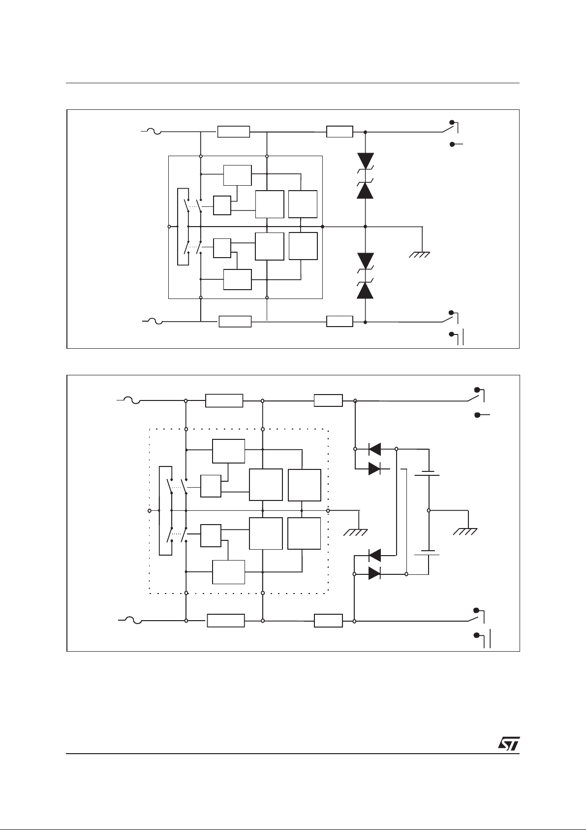
Whenused alone, theCLP270M acts atthe internal overvoltagereference level (+/-270 V). Furthermore,it
is possible to adjust this threshold level to a lower voltage by using:
n
up to 4 fixed external voltage reference (VZ1to VZ4) (see fig. 5a, here-below).
n
external reference supplies, Vb1and Vb2(see fig. 5b, on next page).
3/13
Obsolete Product(s) - Obsolete Product(s) Obsolete Product(s) - Obsolete Product(s)
APPLICATION NOTE
Fig. 5a: Method to adjust the reference voltage.
Fuse
TIP
Rsense
1
Rp
TIPL TIPS
Overcurrent
detector
Overvoltage
detector
Overvoltage
detector
RING
OR
SW3 SW1
FS GND
SW4 SW2
RINGL
OR
Overcurrent
detector
Rsense
Fuse
Fig. 5b: Method to adjust the reference voltage.
Fuse
TIP
Rsense
TIPL TIPS
RINGS
Overvoltage
reference
(+/- 270 V)
Overvoltage
reference
(+/- 270 V)
2
VZ1
VZ2
VZ3
VZ4
1
Rp
2
1
Rp
2
Overcurrent
detector
VB1
VB2
1
2
RING
Overvoltage
OR
SW3 SW1
FS GND
SW4 SW2
RINGL
OR
Overcurrent
detector
detector
Overvoltage
detector
RINGS
Overvoltage
reference
(+/- 270 V)
Overvoltage
reference
(+/- 270 V)
Rsense
Fuse
Rp
4/13

Obsolete Product(s) - Obsolete Product(s) Obsolete Product(s) - Obsolete Product(s)
APPLICATION NOTE
4. Speech mode
In speech mode (Ring relay in position 1), the protection is provided by the combination of both CLP270M
and the external voltage reference device (see figure 6)
Fig. 6: Switching by current during speech mode.
I
Fuse
TIP
Innormal conditions, theworking pointof this circuitis located inregion 4 ofA2 curve :the CLP270M isidle.
Whena surge occurs on the line, theexternal voltage reference deviceclamps at GNDor -V
for positive and negative surges.
This generates a current which is detected by R
short-circuited to GND.
The operating point moves to region 5 for positive surges or region 6 for negative surges.
Once the surge current falls belowthe switching-off current I
(region 4).
The choice of the switching-on currents is function of the R
In normal operating condition the current (typically below -100 mA) should not activate the protection
device CLP270M. Therefore the level of activation has to be chosen just above this limit (-200 mA). This
level is adjusted through R
Figures 7a and 7b enable the designers to choose the right R
Example:
Thechoice of R
positive triggering will be 150mA min and 280 mA max.
LG
Rsense
TIPL TIPS
Overcurrent
detector
Overvoltage
Overvoltage
detector
OR
SW3 SW1
FS
sense
=4Ωensuresa negative triggering of-190 mA min and -320mA max. In this case, the
sense
reference
(+/- 270 V)
.
GND
V
LG
1
Rp
2
sense
-Vbat
External
voltage
reference
-V
and causes the protection to act : the line is
, the CLP270M returns to itsinitial state
SWOFF
resistors.
sense
value.
sense
REF2
ILG
A2
5
4
V
REF1
6
respectively
bat
V
LG
Fig. 7a and 7b: Switching-on current versus R
sense
.
ISWON (T, Rsense) / ISWON (25°C, 4 )Ω
2
@-20°C @25°C @75°C
1
Iswon @ 25°C (mA)
500
300
Iswon min
negative
Iswon max
negative
Iswon min
positive
Iswon max
positive
200
0.5
0.3
0.2
3 5 7 9 11 13
100
50
357911
Rsense ( )Ω
Rsense ( )Ω
5/13

Obsolete Product(s) - Obsolete Product(s) Obsolete Product(s) - Obsolete Product(s)
APPLICATION NOTE
5. Failure Status
The CLP270M has an internal feature that allows
the user to get a Failure Status (FS) indication.
When the CLP270M is short-circuiting the line to
GND, a signal can be managed through pin 1. This
signal can be used to turn a LED on in order to
providea surge indication.It may alsobe used with
a logic circuitry to count the number of
disturbances appearing on the lines.
If a surge exceeding the maximum ratings of the
CLP270Moccurs on theline, thedevice will failin a
short-circuit state.
The figure 9 shows two different curves :
n
The lower one indicates the maximum
guaranted working limits of the CLP270M.
The upper curve shows the limit above which the
CLP270M is completely destructed . In this case,
the Fail Diagnostic pin is on.
Fig. 8: Failure Status circuit and diagnostic.
Rsense
1
FAILURE
STATUS
1k
+12V
CLP270M
Rsense
Fig. 9 : Operation limits and destruction zone of
the CLP270M.
5 000
2 000
1 000
500
200
100
50
20
10
0.01 0.02 0.05 0.1 0.2 0.5 1 2 5 10
t (ms)
CLP270M TEST RESULTS ACCORDING TO BELLCORE 1089 REQUIREMENTS
1. BELLCORE GR-1089-CORE requirements:
Tables 1 and 2 summarize the lighting surges required by the bellcore 1089.
Tables 1 to 6 summarize the surge needs defined by Bellcore regarding both lightningand AC power fault.
In case of first level test, the equipment under test shall be operating after the surge. For the second level
tests, the equipment under test may be damaged, but no fire or electrical safety hazard may occur.
6/13

Obsolete Product(s) - Obsolete Product(s) Obsolete Product(s) - Obsolete Product(s)
Table 1: First level lightning surge.
APPLICATION NOTE
Surge Minimum
peak voltage
(volts)
1 +/- 600 100 10/1000 25 A
2 +/- 1000 100 10/360 25 A
3 +/- 1000 100 10/1000 25 A
4 +/- 2500 500 2/10 10 B
5 +/- 1000 25 10/360 5 B
Table 2: Second level lightning surge.
Surge Minimum
peak voltage
(volts)
1 +/- 5000 500 2/10 1 B
per conductor
per conductor
Minimum
peak current
(Amps)
Minimum
peak current
(Amps)
Maximum rise
/ Minimum
decay time for
voltage and
current
(µs)
Maximum rise
/ Minimum
decay time for
voltage and
current
(µs)
Repetitions,
each polarity
Repetitions,
each polarity
Test
connections
per
table 4.1
Test
connections
per
table 4.1
Table 3: First level AC power fault (table 4-7 of GR-1089-CORE issue 2, december 1997).
Test Voltage
)
(V
RMS
1 50 0.33 15 minutes Removed A
2 100 0.17 15 minutes Removed A
3 200, 400
and 600
4 1000 1 60 1s
5 see figure 4-3 see figure 4-3 605s
6 600 0.5 30s Removed A
7 600 2.2 2s Removed A
Short circuit
current per
conductor
(Amps)
1 (at 600V) 60 1 s
Duration Primary
application of
each voltage
applications
applications
protection
Removed A
Operative
protector in place
Removed see figure 4-3
connections
table 4.1
Test
per
B
8 600 3 1s Removed A
9 1000 5 0.5s Operative
protector in place
B
7/13

Obsolete Product(s) - Obsolete Product(s) Obsolete Product(s) - Obsolete Product(s)
APPLICATION NOTE
Table 4: Second level AC power fault (table 4-8 of GR-1089-CORE issue 2, december 1997).
Test Test for Voltage
(V
RMS
1 Secondary
contact
2 Primary
contact
3 Short-term
fault induction
4 Long-term
fault induction
5 High impedance induction 15 minutes
Table 5: Test connection (table 4-1 of GR-1089-CORE).
Test Two-wire interface Four-wire interface
A
1. Tip to generator, Ring to ground
2. Ring to generator, Tip to ground
120, 277 25 15minutes A
600 60 5seconds A
600 7 5 seconds A
100-600 2.2
Short circuit
)
current per
conductor
(Amps)
(at 600 V)
1. Each lead (T, R, T1, R1) to generator with
other three leads grounded
2. Tip and Ring to generator simultaneously, T1
and R1 to ground
Duration
15 minutes A
Test
connections
per
table 4.1
3. Tip to generator, Ring to generator
simultaneously
B
Tip to generator, Ring to generator
simultaneously
S1
Limiting
resistance
(IF specified)
V oltage
Source
Test
S3
3. T1 and R1 to generator simultaneously,
Tip and Ring to ground
T, R, T1, R1 to generator simultaneously
Switch
S2
S4
unit
under
test
T
E
R
M
T
E
R
M
8/13

Obsolete Product(s) - Obsolete Product(s) Obsolete Product(s) - Obsolete Product(s)
APPLICATION NOTE
Table 6: Application of lightning and AC power fault test voltages (table 4-2 of GR-1089-CORE).
Test S1 S2 S3 S4
T to generator, R to ground
(condition A1 of table 4-1)
R to generator, T to ground
(condition A2 of table 4-1)
T to generator, R to generator
simultaneously
(condition A3 of table 4-1)
2. First level lightning surge:
2.1. Ringing mode
Lightning phenomena are the most common surge causes. The purpose of this test is to check the
behavior of the CLP270M against these lightning strikes.
Figures 11 and 12 show that the remaining overvoltage does not exceed +/- 500 V. The CLP270M
switches on within 250ns and withstands the 500A given by the BELLCORE 2/10µs generator.
Fig. 10: Lightning simulation test.
Closed Open Open Closed
Open Closed Closed Open
Closed Open Closed Open
I1
2/10 µs
GENERATOR
+/- 2.5 kV
(500 A)
Fig. 11: CLP270M response to a positive surge. Fig. 12 : CLP270M response to a negative surge.
TIPL
1/2 CLP270M
4
Rsense
GND
Rp
TIPS
V1
9/13

Obsolete Product(s) - Obsolete Product(s) Obsolete Product(s) - Obsolete Product(s)
APPLICATION NOTE
Fig. 13: Lightning test in speech mode.
I
1
2/10 µs
GENERATOR
+/- 5 kV
(500 A)
2.2. Speech mode
Figures 14 and 15 give the voltage and current behaviorduring positive andnegative 2.5kV, 2/10µs,500A
surge tests using a LCP1511D as second stage protection device. The firing threshold values are now
adjustedto GND and to -Vbat (-48V) by theaction of the second stage protection whichacts as an external
voltage reference.
Asshown on thesefigures, the maximumremaining voltage doesnot exceed +8.5Vfor positive surgesand
-65V for negative surges.
Fig. 14: CLP270M response to a positive surge. Fig. 15: CLP270M reponse to a negative surge.
TIPL
1/2 CLP270M
4
Rsense
TIPS
GND
50
Rp
V1
I2
-48V
LCP1511D
SLIC
V2
10/13

Obsolete Product(s) - Obsolete Product(s) Obsolete Product(s) - Obsolete Product(s)
APPLICATION NOTE
3. Second level lightning surge
3.1. Lightning test in ringing mode
The figures 17 and 18 give the voltage and current behavior during positive and negative 5kV,
2/10µs,500A surge with the CLP270M acting in Ringing mode.
Fig. 16: Lightning test in Ringing mode.
I
1
2/10 µs
GENERATOR
+/- 5 kV
(500 A)
Fig. 17: CLP270M response to a positive surge.
TIPL
1/2 CLP270M
4
Rsense
TIPS
GND
Fig. 18: CLP270M response to a negative surge.
Rp
V1
3.2. Speech mode
Thefigures 20 and22 give thevoltage and currentbehavior during positiveand negative 5kV,2/10µs,500A
surge with the CLP270M acting in speech mode.
The CLP270M withstands the second level lightning surge test without trouble in both ringing and speech
mode.
11/13

Obsolete Product(s) - Obsolete Product(s) Obsolete Product(s) - Obsolete Product(s)
APPLICATION NOTE
Fig. 19: Lightning test in Speech mode.
I
1
2/10 µs
GENERATOR
+/- 5 kV
(500 A)
TIPL
1/2 CLP270M
Fig. 20: CLP270M response to a positive surge.
4
Rsense
GND
50
Rp
I2
SLIC
TIPS
-48V
V1
V2
LCP1511D
Fig. 21: CLP270M response to a negative surge.
4. First and second level AC Power fault.
4.1. Ringing mode
Thefigures 23 and 25 give thevoltage and current at the CLP270M terminals in Ringing mode and Speech
mode.
Fig. 22: AC power fault test in Ringing mode. Fig. 23: Example of behavior when facing test 3
(400V, 600Ω).
I1
Rs
V(RMS)
50Hz
4
Rsense
TIPL TIPS
1/2 CLP270M
GND
Rp
V1
12/13

Obsolete Product(s) - Obsolete Product(s) Obsolete Product(s) - Obsolete Product(s)
APPLICATION NOTE
Fig. 24: AC power fault test in Speech mode.
Fig. 25: Example of behavior when facing test 3
(400V, 600Ω).
V(RMS)
50 Hz
I1
Rs
TIPL
1/2 CLP270M
4Ω
Rsense
GND
TIPS
Ω
50
Rp
-48V
LCP1511D
SLIC
V2
CONCLUSION
The CLP270M is able to withstand all the first level AC power fault tests as required in the table 4-7 of
GR-1089-CORE standard, and then is suitable to protect the linecard.
As usual, for the second level AC power fault tests serial protection as PTC or fuse are needed.
All these curves, lightning and AC power fault represent the behavior of the CLP270M in worst case tests,
anyhow the CLP270M withstands all the others surges of the Bellcore GR1098 standard. For the second
level AC power fault test, the use of series protection elements (PTC or fuses) are needed.
The FS pin allows the system to monitor and record the number of surges occuring on the telecom line.
Informationfurnishedisbelieved to be accurate and reliable. However, STMicroelectronics assumes no responsibility for the consequences of
useof such information nor for any infringement of patents or otherrightsof third parties which may result from its use. No licenseisgranted by
implication or otherwise under any patent or patent rights of STMicroelectronics. Specifications mentioned in this publication are subject to
change without notice. This publication supersedes and replaces all information previously supplied.
STMicroelectronics products are not authorized for use as critical components in life support devices or systems without express written approval of STMicroelectronics.
The ST logo is a registered trademark of STMicroelectronics
© 2000 STMicroelectronics - Printed in Italy - All rights reserved.
STMicroelectronics GROUP OF COMPANIES
Australia - Brazil - China - Finland - France - Germany - Hong Kong - India - Italy - Japan - Malaysia
Malta - Morocco - Singapore - Spain - Sweden - Switzerland - United Kingdom - U.S.A.
http://www.st.com
13/24
 Loading...