

Page 1
AN1216
APPLICATION NOTE
Implementing a Periodic Alarm with TIMEKEEPER
The TIMEKEEPER M48T59 and M48T59Y, from STMicroele ctronics, each provide an 8K x 8 bit non
volatile static RAM, and an integrated real time clock. Each also provides an alarm which can be set either
for a given time and day, or to repeat at a certain day in every month, or at a certain hour in every day, or
at a certain minute of every hour, or at a certain second of every minute. With this functionality already
provided in the hardware, the software to implement an alarm of any given period is greatly simplified, as
described in this document.
Although specifically tailored for the M48T59 (or M48T59Y) device, the ideas can be adapted easily to use
any of ST’s other TIMEKEEPER devices that have the alarm feature. Some modifications in the MCU
memory mapping (the TIMEKEEPER address space) and in the MCU register mapp ing (such as the
pointer to register address) would need to be made.
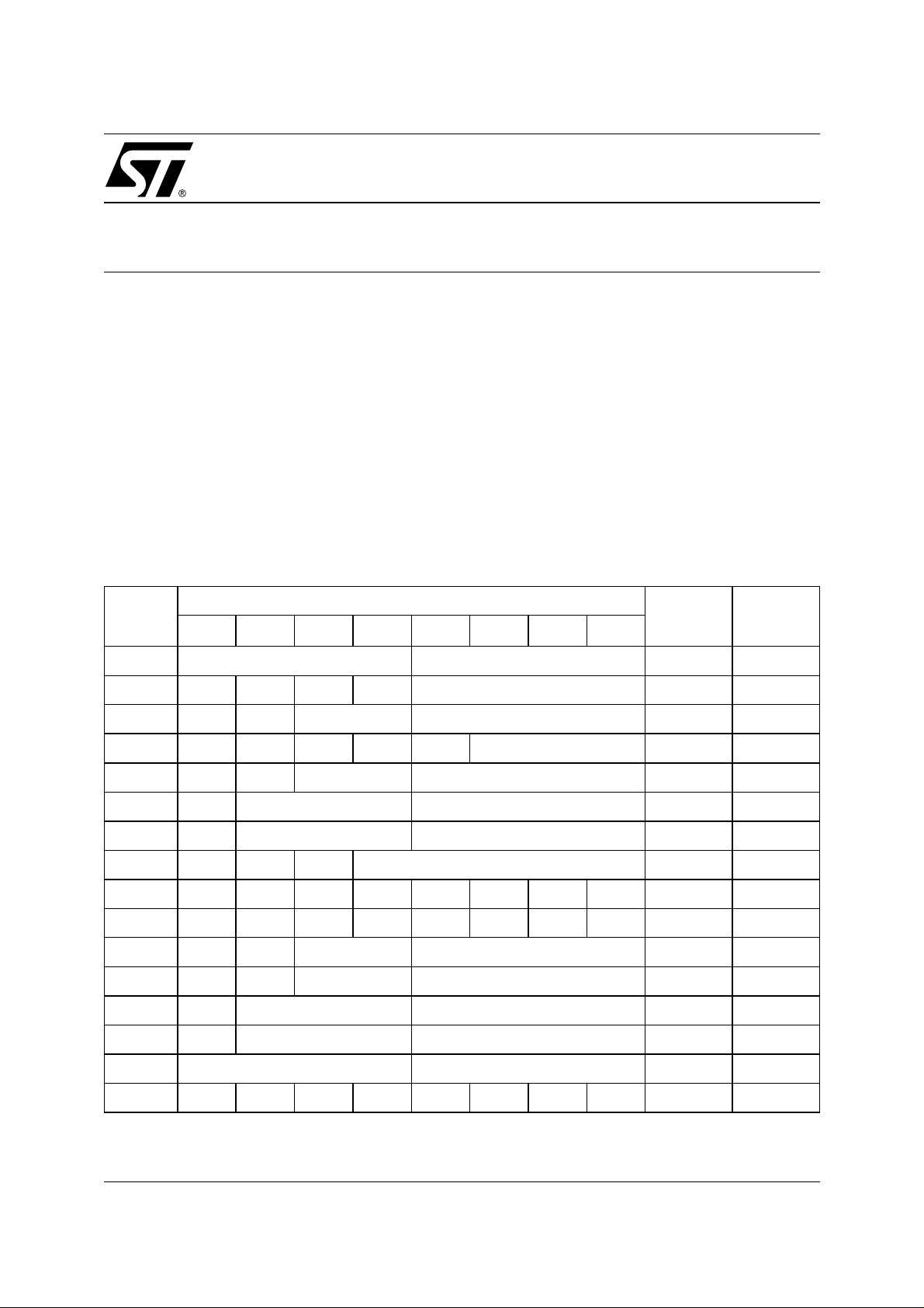
Table 1. Typical TIMEKEEPER (M48T59) Register M ap
Address
Data
Function
D7 D6 D5 D4 D3 D2 D1 D0
Range
(in BCD
Format)
1FFFh 10 Years Year Year 00-99
1FFEh 0 0 0 10M Month Month 01-12
1FFDh 0 0 10 Date Date Date 01-31
1FFCh 0 FT 0 0 0 Day Day 01-7
1FFBh 0 0 10 Hours Hours Hour 00-23
1FFAh 0 10 Minutes 10 Minutes Minute 00-59
1FF9h ST 10 Seconds Seconds Second 00-59
1FF8h W R S Calibration Control
1FF7h WDS BMB4 BMB3 BMB2 BMB1 BMB0 RB1 RB0 Watch
1FF6hAFE0ABE00000Interrupt
1FF5h RPT4 0 AI 10 Date Alarm Date A Date 01-31
1FF4h RPT3 0 AI 10 Hour Alarm Hour A Hour 00-23
1FF3h RPT2 Alarm 10 Minutes Alarm Minutes A Minute 00-59
1FF2h RPT1 Alarm 10 Seconds Alarm Seconds A Second 00-59
1FF1h unused unused unused
1FF0hWDFAF0BLZZZZFlags
February 2000 1/8
Page 2

AN1216 - APPLICATION NOTE
TIMEKEEPER CONFIGURATION
The TIMEKEEPER register mapping is shown in Table 1. This is divided in two parts: the clock registers
and the alarm registers.
Clock Registers
The clock registers can be configured in the C language computer program as follows:
*TIMEKEEPER_CAL |= 0x80
*TIMEKEEPER_SEC= 00 //user clock setting : seconds parameter
*TIMEKEEPER_MIN= 00 //user clock setting : minutes parameter
*TIMEKEEPER_HOUR= 00 //user clock setting : hours parameter
*TIMEKEEPER_CAL&= 0x7F
The process for starting the clock and making the calibration adjustments are described in the
data sheet, and in application notes
AN925
and
AN934
.
Alarm Registers
It is necessary to set the Write bit, W, at the top of the control register (at address offset 1FF8h) before
proceeding to any c lock modification. Modi fications to the alarm regist ers, though, can be made at any
time, with no prior changes to the control register being necessary.
The program listing, at the end of this document, contains statements to perform the following functions:
1. The Stop bit (ST, bit 7 of the register at offset 1FF9h) has to be reset to start the TIMEKEEPER oscillator
*TIMEKEEPER_SEC &= 0x7F; // reset bit D7 using a mask 0x7F
2. The Alarm Flag Enable (AFE) bit (bit 7 of the register at offset 1FF6h) is set, thereby allowing the IRQ
pin (pin 26) to output the interrupt signal (active low).
*TKPER_AL_IT |= 0x80; // set bit D7 using a mask 0x80
3. The flag register (a t offset 1F F0h) mus t be read at the beginning of the alarm updat ing rou tine. If not,
the AF flag will never be released, and the TIMEKEEPER will continuously output an inte rrupt to the
MCU, and the system will become jammed.
M48T59
SOFTWARE CONFIGURATION
The program is listed on page 4. To unders tand its operation, it is important to distinguish between t he
three pointer variables, pointing to physical addresses in the hardware:
*TKPER_AL_HOUR, *TKPER_AL_MIN, *TKPER_AL_SEC
and the three integer variables, used as work-space by the software:
alarm_hour, alarm_minute, alarm_second
The first three variables are poin ters to the phy sical a ddress of the values that are stored in the M48T59
memory device.
The three software variables are used to hold the user’s data (they specify the period of the alarm in hours,
minutes and seconds). T his is not the same information as is stored in the TIMEKEEPER registers, as
pointed to by the pointer variables, but is used in their calculation.
The program does make use of the four Repeat bits (RPT4, RPT3, RPT2 and RPT1) that are physically
located i n the TIM EKEEPER d evice. These should a ll be se t, exc ept fo r those corre sponding to fields that
contain significant data. For instance, to set an alarm that repe ats every 3 minutes and 45 s econds, the
alarm_minutes
and
alarm_seconds
variables would be loa ded with these two values. Then a ppropriate
values would be calculated for load ing in the “Alarm Minutes” and “Alarm Seconds” fields of the alarm
registers (at addresses 1 FF3h a nd 1FF2h, *TKPER_AL_MIN and *TKPER_AL_SEC, respectively), and
their Repeat bits (RPT2 and RPT1, respectively) would be reset to ‘0’. Meanwhile, the
alarm_hour
variable, and the “Alarm D ate” and “Alarm H our” fields of the alarm reg isters (at address es 1FF5h and
1FF4h, *TKPER_AL_DATE and *TKPER_AL_HOUR, respectively) would be treated as “Don’t Care”, as
2/8
Page 3
AN1216 - APPLICATION NOTE
indicated by their Repea t bits (RPT4 and RPT3, respectively) being set. This is s ummarized i n Table 2,
with the three local integer variables,
period.
Table 2. Bit Setting to Control the Period of the Repeated Alarm
RPT4 RPT3 RPT2 RPT1 Periodic alarm activated every
11111 second
1 1 1 0 alarm_second seconds (less than 1 minute)
1 1 0 0 alarm_minute minutes alarm_second seconds (less than 1 hour)
1 0 0 0 alarm_hour hours alarm_minute minutes alarm_second seconds (less than 1 day)
For example, to set a period of 1 hour 49 minute 35 seconds, the procedure is as follows:
RPT4 = 1
RPT3 = RPT2 = RPT1 = 0
alarm_second = 0x35
alarm_minute = 0x49
alarm_hour = 0x01
Or, to set a period of 49 minute 35 seconds, the procedure is as follows:
RPT4 = RPT3 = 1
RPT2 = RPT1 = 0
alarm_second = 0x35
alarm_minute = 0x49
alarm_hour = DontCare
alarm_second, alarm_minute
and
alarm_hour
, used to represent the
SOFTWARE IMPLEMENTATION
TIMEKEEPER Data Format
TIMEKEEPER data is held as BCD (binary coded decimal). This is handled in the C programming
language using th e ‘ uns igne d char’ data type. Th is can be converted within the C prog ra m to other data
types, such as ‘integer’, for numeric processing. Two functions are prov ide d in the program at the end of
this document for making this conversion.
– Char_To_Int: to take a BCD parameter, and to return the equivalent integer value
– Int_To_Char: to take an integer parameter, and to return the equivalent BCD value.
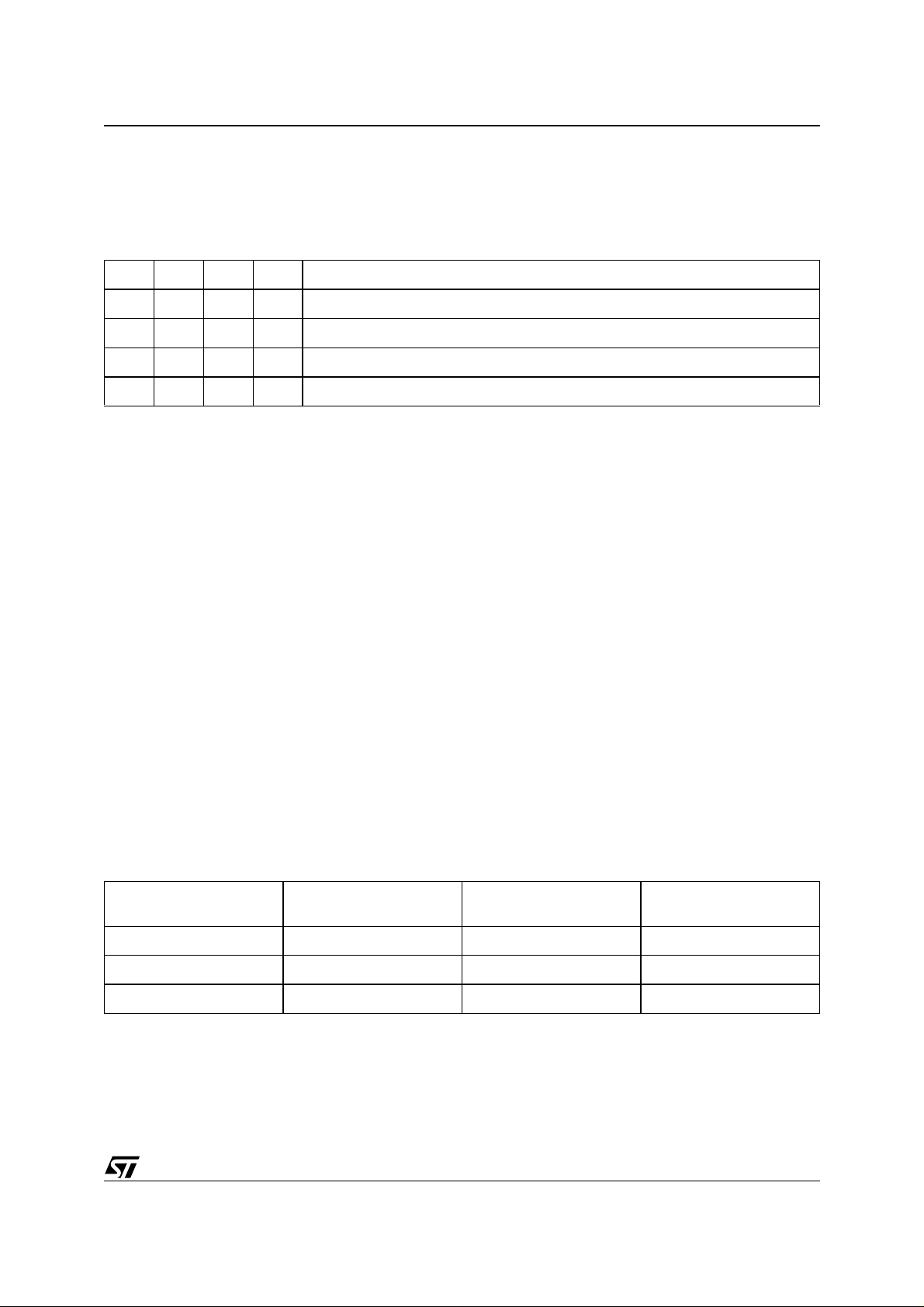
The valid ranges for the alarm fields are summarized in Table 3.
Tabl e 3. TIMEKEEPER Data Format
Data C language type
Alarm second 0-59 00-3B 0-59
Alarm minute 0-59 00-3B 0-59
Alarm hour 0-12 00-0B 0-12
Int (integer)
Decimal
Char (character)
Hexadecimal
Char (character)
BCD
Alarm Update Management
When the alarm signal is g enerated by the TIME KEEPER device, it is communicated to the MCU. The
MCU can monit or for th is event either by po lling, or b y usi ng interr upts. T here ar e two v arian ts of eac h
method:
■ Polling
3/8
Page 4

AN1216 - APPLICATION NOTE
– Read the flag register and check the AF bit (bit 6 of the register at offset 1FF0h)
– Output the alarm signal on the TIMEKEEPER IRQ pin (pin 26), and read it on the MCU I/O port
■ Interrupts
– Give priority to processing the alarm interrupt
– The alarm signal is used to cause a wake up event
The last option is ideally suited when power consumption is the critical issue. For instance, when
measuring, processing and storing some metering data ev ery three minutes, the MCU can stay in its
stand-by state for 95% of the time, and only run at full speed, with high power consum ption, during the
other 5% of the time.
The other interrupt option is ideally suited when service time is the critical issue. The MCU will be
interrupted from whatever processing it was currently engaged in, to service the alarm event. This can be
integrated into a hierarchy of prioritized interrupts.
The two polling options are equally suited when the MCU needs to run at full speed, and full power, all of
the time, executing important backgroun d work, only respond ing to the alarm e vent when it has n othing
else to do.
In polling method, the MCU is always running full speed and fu ll power consumption. In this case, t he
application power consumption is not a key issue and/or the process to be executed due to an alarm which
has no priority. The alarm check and update is served as every other application routine.
The TIMEKEEPER IRQ
In the following program, a routine “Update_Next_Ala rm” is provided to take care of the period ic update
of the alarm parameters.
The program has been written in ANSI C, and has been compiled and tes ted with an M68HC11 series
MCU.
pin (pin 26) is an active low signal.
/* TIMEKEEPER ; M48T59/59Y PERIODIC ALARM SOURCE CODE : */
/* Version: 1.01 */
/****************************************************************************/
/* Copyright (c) 1999 STMicroelectronics. */
/* */
/* This program is provided “AS IS” WITHOUT WARRANTY OF ANY KIND, EITHER */
/* EXPRESSED OR IMPLIED, INCLUDING BUT NOT LIMITED TO, THE IMPLIED WARRANTY */
/* OF MERCHANTABILITY AND FITNESS FOR A PARTICULAR PURPOSE. THE ENTIRE RISK */
/* AS TO THE QUALITY AND PERFORMANCE OF THE PROGRAM IS WITH YOU. SHOULD THE */
/* PROGRAM PROVE DEFECTIVE, YOU ASSUME THE COST OF ALL NECESSARY SERVICING, */
/* REPAIR OR CORRECTION. */
/****************************************************************************/
/****************************************************************/
/* */
/* This program controls the TIMEKEEPER alarm hardware so */
/* as to provide the functionality of a periodic alarm. */
/* */
/****************************************************************/
#include <mcu_hc11.h> // this was developed on HC11 platform
#include <m88xxfx.h> // M88 Flash+PSD register map
extern volatile unsigned char dip_sw;
/*****************************************************************/
/* TIMEKEEPER memory map */
/* Depend on your system and your TIMEKEEPER. */
/* The device is M48T59 series, 8kx8 non volatile SRAM, 16 clock */
/* alarm registers in address 1FF8h to 1FFFh */
/* In this example, the TIMEKEEPER was mapped from 4000h to 5FFFh*/
/*****************************************************************/
4/8
Page 5

AN1216 - APPLICATION NOTE
/*
#ifndef _MEM_MAP_H
#define _MEM_MAP_H
#define EXT_RAM_BASE (unsigned int) 0x4000
#define TIMEKEEPER_HOUR (unsigned char *) 0x5FFB
#define TIMEKEEPER_MIN (unsigned char *) 0x5FFA
#define TIMEKEEPER_SEC (unsigned char *) 0x5FF9
#define TIMEKEEPER_CAL (unsigned char *) 0x5FF8
#define TKPER_AL_IT (unsigned char *) 0x5FF6
#define TKPER_AL_DATE (unsigned char *) 0x5FF5
#define TKPER_AL_HOUR (unsigned char *) 0x5FF4
#define TKPER_AL_MIN (unsigned char *) 0x5FF3
#define TKPER_AL_SEC (unsigned char *) 0x5FF2
#define TKPER_FLAG (unsigned char *) 0x5FF0
#endif
*/
/*****************************************************************/
/* function Char_To_Int */
/* description : This function convert the timekeeper data*/
/* (in BCD format) to an integer. */
/* input : char byte */
/* output : integer */
/* example : octet = 0x33 (51 in integer) */
/* Char_To_Int = 33 (0x21 in hexa) */
/*****************************************************************/
int Char_To_Int(unsigned char octet)
{
int buffer;
buffer = (int)(octet);
if (octet <= 0x09) return(buffer);
if ((octet >= 0x10) & (octet <= 0x19)) return (buffer-6);
if ((octet >= 0x20) & (octet <= 0x29)) return (buffer-12);
if ((octet >= 0x30) & (octet <= 0x39)) return (buffer-18);
if ((octet >= 0x40) & (octet <= 0x49)) return (buffer-24);
if ((octet >= 0x50) & (octet <= 0x59)) return (buffer-30);
}
/*****************************************************************/
/* function Int_To_Char */
/* description : This function convert an integer data */
/* to BCD TIMEKEEPER format (unsigned char) */
/* input : int integ */
/* output : unsigned char */
/* example : integ = 33 (0x21 in hexa) */
/* Int_To_Char = 0x33 (51 in integer) */
/*****************************************************************/
unsigned char Int_To_Char(int integ)
{
char buffer;
buffer = (unsigned char)(integ);
if (integ <= 9) return(buffer);
if ((integ >= 10) & (integ <= 19)) return (buffer+6);
if ((integ >= 20) & (integ <= 29)) return (buffer+0x0C);
if ((integ >= 30) & (integ <= 39)) return (buffer+0x12);
if ((integ >= 40) & (integ <= 49)) return (buffer+0x18);
if ((integ >= 50) & (integ <= 59)) return (buffer+0x1E);
}
/*****************************************************************/
/* void Update_Next_Alarm */
/* description : After alarm interupt, it will : */
/* - reset the TIMEKEEPER IT flag */
/* - read the actual time in the clock register */
/* - calculate the next alarm time */
/* - update the alarm register */
/* to prepare for the next alarm */
/* input : alarm period (al_hour, al_minute, al_second) */
/* output : nothing */
5/8
Page 6

AN1216 - APPLICATION NOTE
/*****************************************************************/
void Update_Next_Alarm(int al_hour,int al_minute,int al_second)
{
// time carry, going to be used for hour, minute and second
// calculation process.
unsigned char time_flag = 0;
// intermediate storage for alarm data.
int buffsec;
int buffmin;
int buffhour;
// temporary storage
unsigned char buffchar;
// Touch the flag register to reset TIMEKEEPER AF flag (interupt)
buffchar = *TKPER_FLAG;
/*****************************************************************/
/* This is to update the alarm second register. */
/* It will test if RPT1 is set. If not then it adds “al_second” */
/* to second alarm register. It takes care of the minute carry. */
/*****************************************************************/
if (!(*TKPER_AL_SEC & 0x80)) // if !RPT1
{ // update register with carry
buffsec = Char_To_Int(*TIMEKEEPER_SEC) + al_second;
if (buffsec > 59) // if >59
{ // then restore 60sec format
*TKPER_AL_SEC = Int_To_Char(buffsec-60);
time_flag = 1;
}
else *TKPER_AL_SEC = Int_To_Char(buffsec); // normal case
}
/*****************************************************************/
/* This is to update the alarm minute register. */
/* It will test if RPT2 is set. If not then it adds “al_minute” */
/* to alarm minute register. It takes care of the hour carry. */
/*****************************************************************/
if (!(*TKPER_AL_MIN & 0x80)) // if !RPT2
{ // update register with carry
buffmin = Char_To_Int(*TIMEKEEPER_MIN) + al_minute + time_flag;
if (buffmin > 59) // if >59
{ // then restore 60 min format
*TKPER_AL_MIN = Int_To_Char(buffmin-60);
time_flag = 1;
}
else
{
*TKPER_AL_MIN = Int_To_Char(buffmin); // normal case
time_flag = 0;
}
}
/*****************************************************************/
/* This is to update the alarm hour register. */
/* It will test if RPT2 is set. If not then it adds “al_hour” to */
/* alarm hour register */
/*****************************************************************/
if (!(*TKPER_AL_HOUR & 80))
{
buffhour = Char_To_Int(*TIMEKEEPER_HOUR) + al_hour + time_flag;
if (buffhour > 23) *TKPER_AL_HOUR = Int_To_Char(buffhour-24);
else *TKPER_AL_HOUR = Int_To_Char(buffhour);
}
}
6/8
Page 7

AN1216 - APPLICATION NOTE
main(void)
{
int alarm_second; // relative alarm variable
int alarm_minute;
int alarm_hour;
/*****************************************************************/
/* TIMEKEEPER alarm configuration example. */
/*****************************************************************/
// Memory-mapped unsigned char pointers
*TKPER_AL_HOUR &= 0x7F; // to the external hardware registers
*TKPER_AL_MIN &= 0x7F; // to set a one-off alarm
*TKPER_AL_SEC &= 0x7F; // for a fixed time today.
// Local memory integer variables
alarm_hour = 1; // to hold the repetition period
alarm_minute = 49; // for an alarm (& an interrupt on pin 26)
alarm_second = 35; // every 1hr 49min 35sec (for example).
// Start the Timekeeper oscillator.
*TIMEKEEPER_SEC &= 0x7F;
// RPT4 set
*TKPER_AL_DAY |= 0x80;
// enable IRQ request on pin26 (M48T59)
*TKPER_AL_IT |= 0x80;
while (1)
{
/*******************************************************************/
/* read_the_port is a read of MCU I/O to detect an alarm interrupt */
/* lcd_min_display is a lcd software driver used for routine debug */
/* Those library were developed for FLASH+PSD development board. */
/*******************************************************************/
read_the_ports();
lcd_min_display(0,3,*TIMEKEEPER_HOUR); // display current time
lcd_min_display(0,7,*TIMEKEEPER_MIN);
lcd_min_display(0,13,*TIMEKEEPER_SEC);
if (dip_sw==0x0E) // dip_sw is updated by read_the_port
// if detect alarm interrupt from TIMEKEEPER
{
Update_Next_Alarm(alarm_hour,alarm_minute,alarm_second);
lcd_min_display(1,3,*TKPER_AL_HOUR); // display next alarm time
lcd_min_display(1,7,*TKPER_AL_MIN);
lcd_min_display(1,13,*TKPER_AL_SEC);
}
}
}
7/8
Page 8

AN1216 - APPLICATION NOTE
For current information on all ST products, please consult our pages on the world wide web:
www.st.com
If you have any questions or suggestions concerning the matters raised in this document, please send
them to the following electronic mail addresses:
apps.nvram@st.com
ask.memory@st.com
Please remember to include your name, company, location, telephone num ber and fax number.
(for application support)
(for general enquiries)
Information furnished is believed to be accurate and reliable. However, STMicroelectronics assumes no responsibility for the consequences
of use of such information nor for any infringement of patents or other rights of third parties which may result from its use. No license is granted
by implic ation or otherwise under any patent or p atent right s of STMicroelectr oni cs. Spec i fications mentioned i n this publication are s ubj ect
to change without notice. This publication supersedes and replaces all information previously supplied. STMicroelectronics products are not
authorized for use as cri tical comp onents in life support dev i ces or systems wi thout express written approval of STMicroe l ectronics.
© 2000 STMic roelectronics - All Ri ghts Reserved
The ST logo is a registered trademark of STMicroelectr oni cs.
All other na m es are the prop erty of their respectiv e owners.
STMicroelectronics GROUP OF COMPANIES
Australia - Brazil - China - Finland - France - Germany - Hong Kong - India - Italy - Japan - Malaysia - Malta - Morocco - Singapore - Spain -
Sweden - Switzerland - United K i ngdom - U.S. A.
http://www.s t. com
8/8
 Loading...