

Page 1

AN1105
APPLICATION NOTE
ST7 pCAN PERIPHERAL DRIVER
by Central European MCU Supp ort
INTRODU CT I ON
The Controller Area Network (CAN) norm defines a fast and robust serial bus protocol, suited
for local networking of intelligent devices such as microcontrollers, sensors and actuators. It is
now widely used, mostly in the automoti ve dom ain, but also for hom e automation and i ndustrial equipment control.
Several members of the ST7 MCU family have a built-in CAN peripheral named pCAN, which
allows them to be used as nodes in a CAN network. A software driver provided is by ST to help
you start designing and writing applications using the ST7 pCAN cell.
The purpose o f t he follow ing ap plicati on note is to ex plain to y ou how t o u se the dri ver, and
how it works. Thus, you can either build your software from the provided files, or modify them
to meet specific needs.
You will find in this application note:
– a brief description of the CAN protocol
– an overview of the pCAN peripheral
– the complete description of the user interface
– the step-by-step development of an example application using the driver features
– a technical report including a description of algorithms and internal data types
Version 1.3
AN1105/0801 1/100
1
Page 2

Table of Contents
INTRODUCTION . . . . . . . . . . . . . . . . . . . . . . . . . . . . . . . . . . . . . . . . . . . . . . . . . . . . . . . 1
1 CAN COMMUNICATION PROTOCOL . . . . . . . . . . . . . . . . . . . . . . . . . . . . . . . . . . . . . 4
1.1 GENERAL CHARACTERISTICS . . . . . . . . . . . . . . . . . . . . . . . . . . . . . . . . . . . . . 4
1.1.1 Protocol properties . . . . . . . . . . . . . . . . . . . . . . . . . . . . . . . . . . . . . . . . . . . . . . . . . . . 4
1.1.2 CAN in the OSI reference model . . . . . . . . . . . . . . . . . . . . . . . . . . . . . . . . . . . . . . . . 5
1.2 CAN FRAME . . . . . . . . . . . . . . . . . . . . . . . . . . . . . . . . . . . . . . . . . . . . . . . . . . . . 6
1.2.1 CAN Data Frame . . . . . . . . . . . . . . . . . . . . . . . . . . . . . . . . . . . . . . . . . . . . . . . . . . . . 6
1.2.2 CAN Remote Frame . . . . . . . . . . . . . . . . . . . . . . . . . . . . . . . . . . . . . . . . . . . . . . . . . 7
1.2.3 CAN Error Frame . . . . . . . . . . . . . . . . . . . . . . . . . . . . . . . . . . . . . . . . . . . . . . . . . . . . 8
1.2.4 CAN Overload Frame . . . . . . . . . . . . . . . . . . . . . . . . . . . . . . . . . . . . . . . . . . . . . . . . 8
1.3 PHYSICAL REPRESENTATION OF DATA . . . . . . . . . . . . . . . . . . . . . . . . . . . . . 8
1.3.1 Bit Stuffing . . . . . . . . . . . . . . . . . . . . . . . . . . . . . . . . . . . . . . . . . . . . . . . . . . . . . . . . . 9
1.3.2 Bit timing . . . . . . . . . . . . . . . . . . . . . . . . . . . . . . . . . . . . . . . . . . . . . . . . . . . . . . . . . . 9
1.4 ARBITRATION PHASE . . . . . . . . . . . . . . . . . . . . . . . . . . . . . . . . . . . . . . . . . . . 10
1.4.1 Arbitration Phase . . . . . . . . . . . . . . . . . . . . . . . . . . . . . . . . . . . . . . . . . . . . . . . . . . . 10
1.4.2 Message Acknowledge men t . . . . . . . . . . . . . . . . . . . . . . . . . . . . . . . . . . . . . . . . . . 11
1.5 ERROR MANAGEMENT . . . . . . . . . . . . . . . . . . . . . . . . . . . . . . . . . . . . . . . . . . 11
1.6 ST7 PCAN PERIPHERAL . . . . . . . . . . . . . . . . . . . . . . . . . . . . . . . . . . . . . . . . . 12
1.6.1 Main Features . . . . . . . . . . . . . . . . . . . . . . . . . . . . . . . . . . . . . . . . . . . . . . . . . . . . . 12
1.6.2 Cell Behaviour . . . . . . . . . . . . . . . . . . . . . . . . . . . . . . . . . . . . . . . . . . . . . . . . . . . . . 13
2 CAN DRIVER . . . . . . . . . . . . . . . . . . . . . . . . . . . . . . . . . . . . . . . . . . . . . . . . . . . . . . . 15
2.1 USER INTERFACE . . . . . . . . . . . . . . . . . . . . . . . . . . . . . . . . . . . . . . . . . . . . . . 15
2.1.1 Files Furnished . . . . . . . . . . . . . . . . . . . . . . . . . . . . . . . . . . . . . . . . . . . . . . . . . . . . 15
2.1.2 Architecture . . . . . . . . . . . . . . . . . . . . . . . . . . . . . . . . . . . . . . . . . . . . . . . . . . . . . . . 15
2.1.3 Principle of Use . . . . . . . . . . . . . . . . . . . . . . . . . . . . . . . . . . . . . . . . . . . . . . . . . . . . 16
2.1.4 Interrupts (IT s) . . . . . . . . . . . . . . . . . . . . . . . . . . . . . . . . . . . . . . . . . . . . . . . . . . . . . 17
2.1.5 User Interface Description . . . . . . . . . . . . . . . . . . . . . . . . . . . . . . . . . . . . . . . . . . . . 19
2.2 HO W TO USE THE CAN DRIVER: A DEMO APPLICATION . . . . . . . . . . . . . . 27
2.2.1 Application . . . . . . . . . . . . . . . . . . . . . . . . . . . . . . . . . . . . . . . . . . . . . . . . . . . . . . . . 27
2.2.2 Cell Configuration . . . . . . . . . . . . . . . . . . . . . . . . . . . . . . . . . . . . . . . . . . . . . . . . . . 28
2.2.3 Implementing the Notification Functions . . . . . . . . . . . . . . . . . . . . . . . . . . . . . . . . . 30
2.2.4 Transmissions outside the CAN Interru pt Function . . . . . . . . . . . . . . . . . . . . . . . . . 33
2.2.5 IMPORTANT: Reentrant Functions . . . . . . . . . . . . . . . . . . . . . . . . . . . . . . . . . . . . . 36
3 DETAILED DESCRIPTION . . . . . . . . . . . . . . . . . . . . . . . . . . . . . . . . . . . . . . . . . . . . . 38
3.1 USER INTERFACE FUNCTIONS . . . . . . . . . . . . . . . . . . . . . . . . . . . . . . . . . . . 38
3.2 INTERNAL FUNCTIONS AND DATA TYPES . . . . . . . . . . . . . . . . . . . . . . . . . . 41
3.2.1 Internal Data Types and Variables . . . . . . . . . . . . . . . . . . . . . . . . . . . . . . . . . . . . . . 41
3.2.2 Internal Routines . . . . . . . . . . . . . . . . . . . . . . . . . . . . . . . . . . . . . . . . . . . . . . . . . . . 44
3.3 A FEW WORDS ABOUT DRIVER PERFORMANCE . . . . . . . . . . . . . . . . . . . . 55
3.3.1 CPU Load . . . . . . . . . . . . . . . . . . . . . . . . . . . . . . . . . . . . . . . . . . . . . . . . . . . . . . . . 55
3.3.2 Code Size . . . . . . . . . . . . . . . . . . . . . . . . . . . . . . . . . . . . . . . . . . . . . . . . . . . . . . . . 56
2/100
2
100
Page 3

Table of Contents
4 DRIVER COD E . . . . . . . . . . . . . . . . . . . . . . . . . . . . . . . . . . . . . . . . . . . . . . . . . . . . . . 57
4.1 CAN.C . . . . . . . . . . . . . . . . . . . . . . . . . . . . . . . . . . . . . . . . . . . . . . . . . . . . . . . . . 57
4.2 CAN.H . . . . . . . . . . . . . . . . . . . . . . . . . . . . . . . . . . . . . . . . . . . . . . . . . . . . . . . . . 86
4.3 CAN_CUSTOM.C . . . . . . . . . . . . . . . . . . . . . . . . . . . . . . . . . . . . . . . . . . . . . . . . 90
4.4 CAN_CUSTOM.H . . . . . . . . . . . . . . . . . . . . . . . . . . . . . . . . . . . . . . . . . . . . . . . . 93
4.5 CAN_HR.H . . . . . . . . . . . . . . . . . . . . . . . . . . . . . . . . . . . . . . . . . . . . . . . . . . . . . 96
3/100
1
Page 4

ST7 pCAN PERIPHERAL DRIVER
1 CAN COMMUNICATION PROTOCOL
In the early 80s, electronic appl icati ons appeared i n the automotive world. The need gradually
arose to establish real-time communications between various types of on-board equipment.
In 1986, the CAN bus protocol, designed by Robert Bosch GmbH, was presented to the public
for the first time. In 1989, the first silicon implementing the protocol was issued and in 1991,
the first car equipped with a CAN network was produced.
Today, the protocol is an international norm (ISO 11898). Its relative simplicity, the wide availability of products and services in terms of chips, softwar e libraries, starter kits, cour ses and
training makes the development of applications relatively fast and cheap.
The CAN p rotocol prov ides t he user with very r eliabl e comm unicati on, with a po werful e rror
detection/confinement m echanism. It allows baud rates up to 1Mbaud (for networks o f up to
40m) which makes it able to support real time applications. The bus can of course be configured with lower speeds for larger networks (50kbaud for networks up to 1km long for example).
There were more than 150 million CAN nodes installed at the beginning of 1999.
1.1 GENERAL CHARACTERISTICS
1.1.1 Prot oc ol pr ope r ties
■ Asynchronous serial bus (See “Bit timing” on page 9)
– No clock signal is transmitted, allowing a tw o-wires (high speed CAN see ISO 11898) or
even one-wire communication (low speed CAN, see ISO 11519)
– Each node resynchronizes itself on every falling edge occurring on the bus.
■ CSMA/CA (Carrier Sense Multiple Access/Collision Avoidance)
– Several nodes can request the bus simultaneously (CSMA).
– When such a situation occurs, there is no loss of data and the mes sage with the highest
priority is immediately sent (CA).
■ Multimaster capability (See “Arbitration Phase” on page 10)
– Every CAN node in the network is able to transmit data.
– The arbitration mechanism is decentralized.
■ Object oriented communication
– Each message on the bus carries its own identifier which is an 11-bit (or 29-bit) number.
This field describes the content of the message. It is not an address.
– Consequently, a transmitter doesn’t address data to a peer but simply broadcasts its data.
Each node in the network picks off data from the bus when it recogn izes an identifier that
concerns it.
4/100
Page 5

ST7 pCAN PERIPHERAL DRIVER
■ Message prioritization
– The identifier of a message also indicates the priority of its carrier. During the arbitration
phase, a bitwise comparison of the different identifiers is performed. The message with the
higher identifier being the more urgent, it wins the arbitration and is immediately transmitted.
■ Error management system (See “Error Mana gem ent” on page 11)
– Detection: every node continuously monitors the bus, even if it is not concerned by the cur-
rent transmission, to detect potential violations of the protocol.
– Signalization: any node detecting an error, signals it to its peers and aborts the current
transmission meanwhile. The sender automatically retries transmission within a certain
amount of time. Thus, the consistency of data throughout the network is preserved.
– Confinement: each node implements counters which are incremented (or decremented)
after each detection of an error (or successful operation). A defective station can then
switch itself off when its counters reach a certain value, and thus stop disturbing the bus
operations.
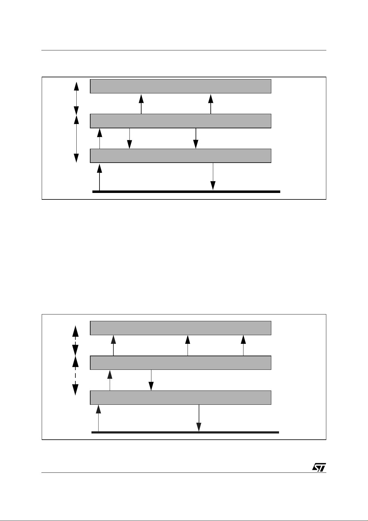
1.1.2 CAN in the OSI reference mo del
The protocol occupies parts of the two lowest lev els (t he physical and data link layers) of t he
7-level ISO/OSI (Open System Interconnection) telecommunications reference model.
Table 1. ISO/OSI Standard Telecommunication Layers
OSI Layer OSI Model CAN Protocol
7 Application No (User defined)
6 Presentation No (User defined)
5 Session No (User defined)
4 Transport No (User defined)
3 Network No (User defined)
2 Data Link Yes
1 Physical Partly
In this reference model, the data link layer deals with physically passing data from one node to
another. It define s arbitrati on, me ssage f raming, er ror m anagem ent a nd tr ansmission timing
for example.
The physical layer deals with putting data on the physical network, and with taking it off. Consequently, it defines signal levels and timings, as well as the transmission support (wire types,
connectors, etc.).
The CAN protoc ol splits the Data L ink lay er into Object and Transfer sublayers, corre-
sponding to the ISO/OSI Logical Link Co nt rol and Medium Access Control sublayers. The
Transfer l ayer is the interf ace betw een the user ap plic ation an d the CA N. The Objec t layer
5/100
1
Page 6
ST7 pCAN PERIPHERAL DRIVER
manages frame s ha ping and a ckno wle dgm ent m e chani sms, b us a rbit ration an d check s t he
formal correctness of the data transmitted and received.
The physical layer is only partly defined, and the user is free to choose the transmission medium for example.
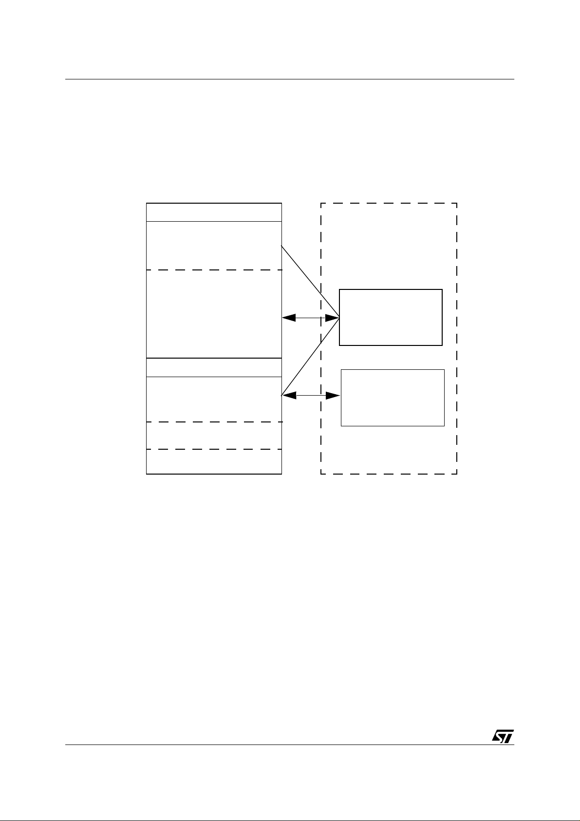
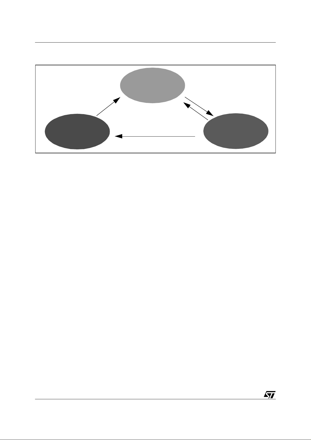
Figure 1. Layered architecture of CAN (ISO 11898 definition)
Data Link Layer
Logical Link Control
Acceptance filtering
Overload Notification
Recovery manageme nt
Medium Access Control
Data encapsulation/decapsulation
Frame coding (stuff/destuff)
Medium access management
Error detection
Error signaling
Acknowledgement
Serialization/Deserialization
Fault confinement
(MAC-Layer Management
Entity)
Physical Layer
Physical Layer Signaling
Bit encoding/decoding
Bit timing
Synchronization
Physical Medium Attachment
Driver/Receiver characteristics
Medium Dependent Interface
Connector
Bus Failure Management
(PLS-Layer Management
Entity)
1.2 CAN FRAME
There are four different CAN frame types: Data frame, Error frame , Remote frame and
Overload frame
There are also two versions of the CAN protocol: 2.0A (or base format) and 2.0B (or extended
format). The 2.0B standa rd introduc es a n ex ten ded data fr ame with a longe r identifi er. B oth
frame types coexist on a CAN 2.0B bus, and its nodes must be at least able to recognize and
acknowledge both.
We will only describe here the 2.0A format, or base format.
1.2.1 CAN Data Frame
The CAN Data frame is used for data transmission and contains the following fields:
■ A start of frame field, consisting of one bit.
■ A 12-bit arbitration field, including:
– An 11-bit identifier
6/100
Page 7
ST7 pCAN PERIPHERAL DRIVER
–A RTR bit used to differentiate data and remote frames. It is dominant in a data frame.
■ A 6-bit control field, including:
– A 4-bit data length code bits giving the size (in bytes) of the data field
–1 IDentifier Extension (IDE) bit ( dom inant for CAN 2.0A frame) and 1 bit reserved for fur-
ther development.
■ A data field of up to 8 bytes.
■ A 16-bit long CRC field. The Cycli c Redundancy Check (CRC) is based on a BCH encoding.
■ A 2-bit acknowledgment field. The transmitters sends it as all recessive. (See “Message
Acknowledgement” on page 11)
■ A 7-bit end-of-frame field.
The interframe space (or Intermission) is the minimum amount of time between two consecutive transmissions.
Figure 2. CAN Data Frame
19 bits
Arbitration Field
Control
Field
0..64 bits
Data Field
CRC Field
25 bits
EOFACK
Interframe
Space
R
11-bit Identifier
DLC
Data
15 bits
7 bits
3 bits
Bus Idle
D
CRC
ACK Delimiter
ACK Slot
SOF
RTR = 0
Delimiter
IDE = 0
1.2.2 CAN Remote Frame
The CAN Remote frame is used to request data. This frame has the same overall constitution
as the data frame. However, in this case, the Rem ote bit (RTR) i s recessive and there is no
data field.
7/100
Page 8
ST7 pCAN PERIPHERAL DRIVER
Figure 3. CAN Remote Frame
19 bits 25 bits
Arbitration Field
IDE = 0
Field
DLC
15 bits Bus Idle3 bits7 bits
CRC
Delimiter
R
11-bit Identifier
D
RTR = 1
SOF
EOFACKCRC FieldControl
ACK Delimiter
ACK Slot
Interframe
Space
1.2.3 CAN Error Frame
The CAN Error frame is sent by a node as soon as it detects a protocol violation in the current
operations on the bus. This frame is composed of 6 successive dominant bits (active error
flag) or recessive (passive error flag), followed by 8 recessive Frame Delimiter bits. The cur-
rent error state of the node sending the error frame (See Section 1.5 "Error Management") will
determine whether it is an acti ve frame (node i n error active state) or a passive frame (node in
error passive state).
1.2.4 CAN Overload Frame
The CAN Overload Frame can be sent during the interframe space to delay the next transmission on the bus. This frame has the same constitution as the active Error frame.
Figure 4. CAN Error/Overload Fram e
Max. 12 bits
Data Frame
R
D
Error/Overload
Flag
6 bits
Error Detection
Error/Overload
Delimiter
8 bits
Interframe
Space
3 bits
Bus Idle or Data Frames
1.3 PHYSICAL REPRESENTATION OF DATA
The CAN data is enco ded w ith NRZ (Non Re turn to Z ero) c ode. The tw o logical l evels us ed
are named dominant ( 0) and recessive (1). Because the CAN cells are connected on the bus
according to the wired-AND principle, it follows that the default bus state is recessive, and that
8/100
Page 9
ST7 pCAN PERIPHERAL DRIVER
transmission of a dominant bit forces this state to dominant, no matter how many other nodes
are transmitting recessive bits.
1.3.1 Bit Stuffing
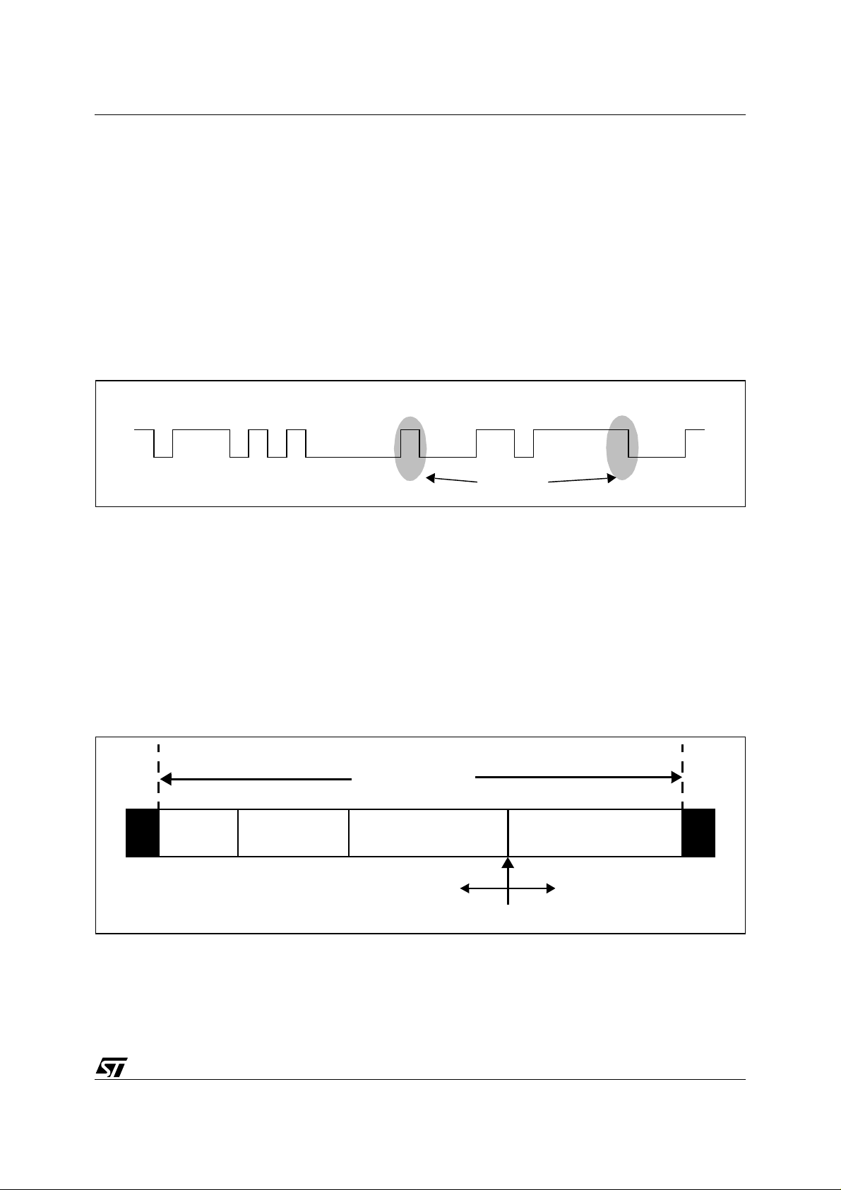
Once built, a frame is passed t o the T ransfer sub-layer, where the CRC is calculated. Then,
Stuffing Bits are inserted in the frame . Each time fiv e conse cutiv e bits of th e same logical
level are detected, a bit of the opposite value is inserted. This is used to generate a minimum
edge rate on the bus for resynchronisation purpose (See “Bit timing” on page 9).
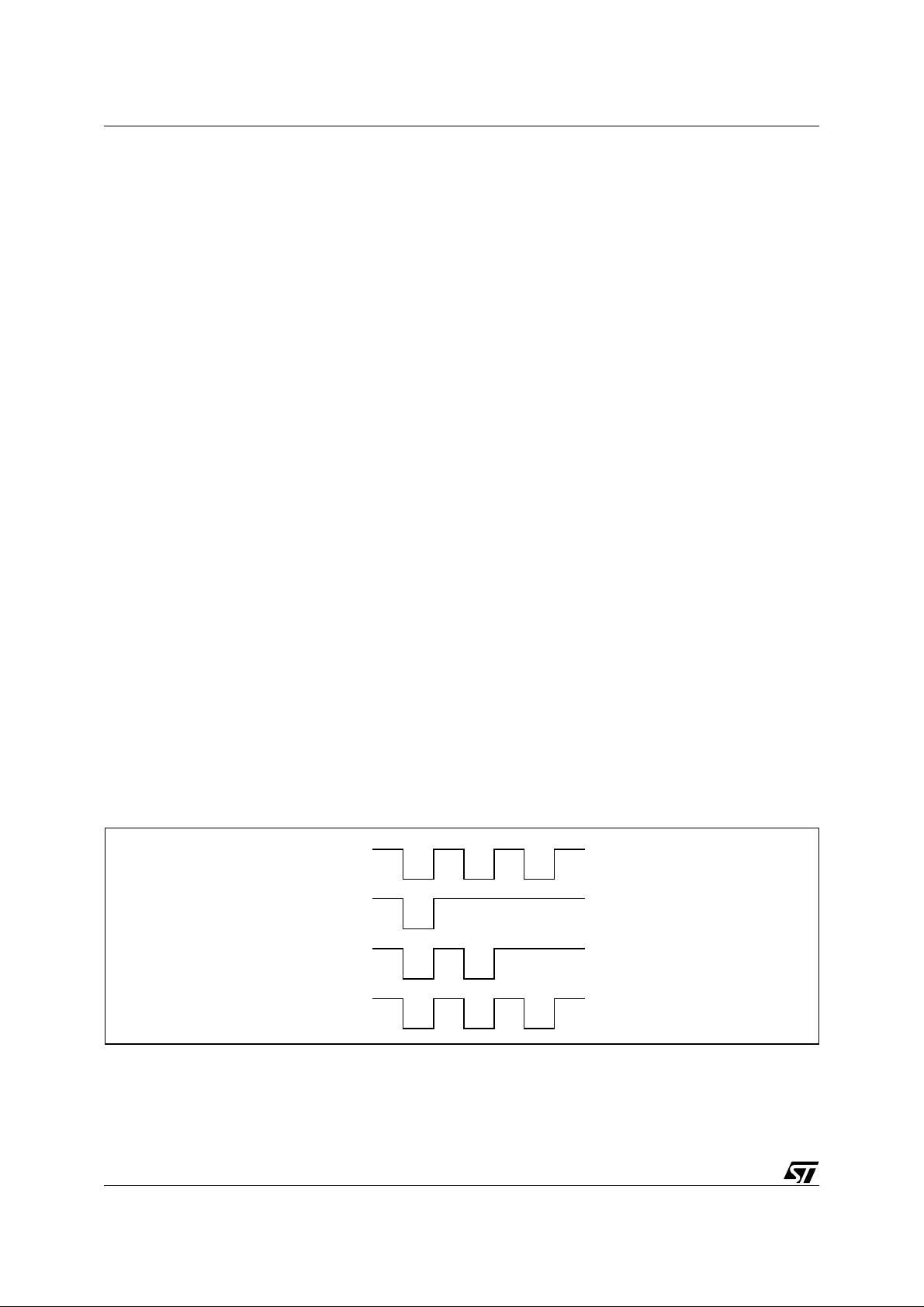
Figure 5. Bit-stream NRZ Code & Bit Stuffing
1 0 1 1 1 0 1 0 1 0 0 0 0 0 1 0 0 0 1 1 0 1 1 1 1 1 0 0 0 1
Stuff bits
1.3.2 Bit timing
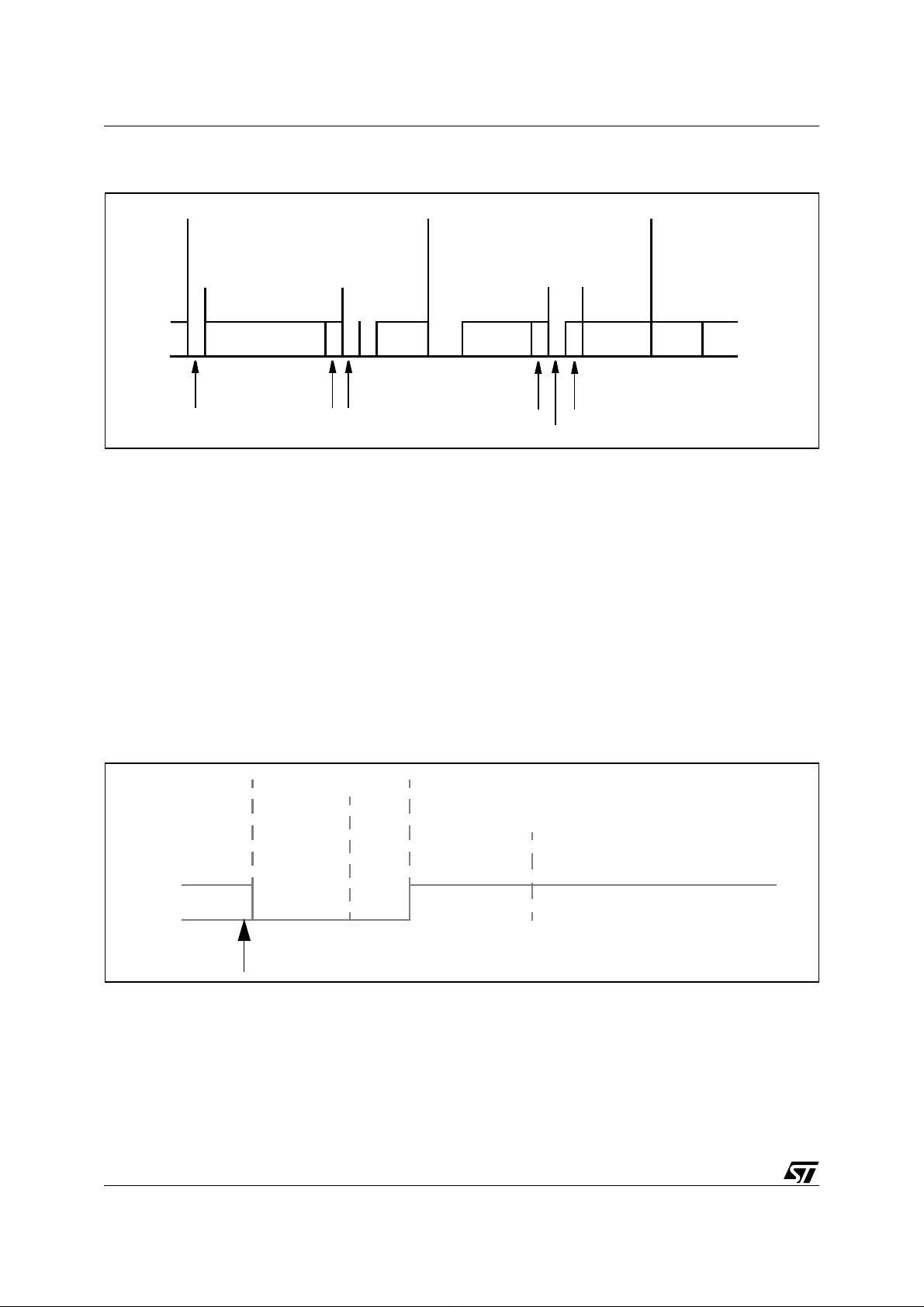
The CAN standard divides the bit time into four segments:
– A synchronisation segment (SYNC),
– A propagation segment (PROP),
– A phase buffer 1 segment (TSEG1),
– A phase buffer 2 segment (TSEG2),
– Each segment is divided into time quanta. The synchronisation segment lasts, by defini-
tion, 1 time quantum.
Figure 6. CAN Bit Segm ents
Previous
Bit
Bit Time
SYNC PROP TSEG1
TSEG2
Sample Point
Next Bit
The CAN communication is asynchronous, i.e. no clock signal is sent together with data. Each
node in the network maintains its own bit timing calculated from the internal clock of the device.
9/100
Page 10
ST7 pCAN PERIPHERAL DRIVER
To deal with signal phase variations on the transmission line due mostly to desynchronization
between clocks of bus participants, TSEG1 and TSEG2 are of variable length. A resynchronization of the local clock occurs on every r ecessive-to-dominant state change. If such a change
arises before (or after) the SYNC segment expected by the cell, TSEG1 (or TSEG2) is lengthened (or shortened) to correct the detected variation. If the edges occur during the SYNC segment, the node assumes that it is synchronized.
The PROP segmen t takes into accoun t the m axim um propag ation ti me of the si gnal on the
network, ensuring that all the nodes sample the same bit at the same ti m e .
The sampling point of the bit takes place between TSEG1 and TSEG2.
1.4 ARBITRATION PHASE
1.4.1 Arbitration Phase
All the cells connected on the CAN network are likely to transmit a message at any time. A cell
can initiate a transmission only when the bus is idle. On transmission of a message, a cell simultaneously monitors the state of the bus to detect potential problems.
If the bus is idle, any cell that is ready for transmission begins to send its data. The other
nodes listen.
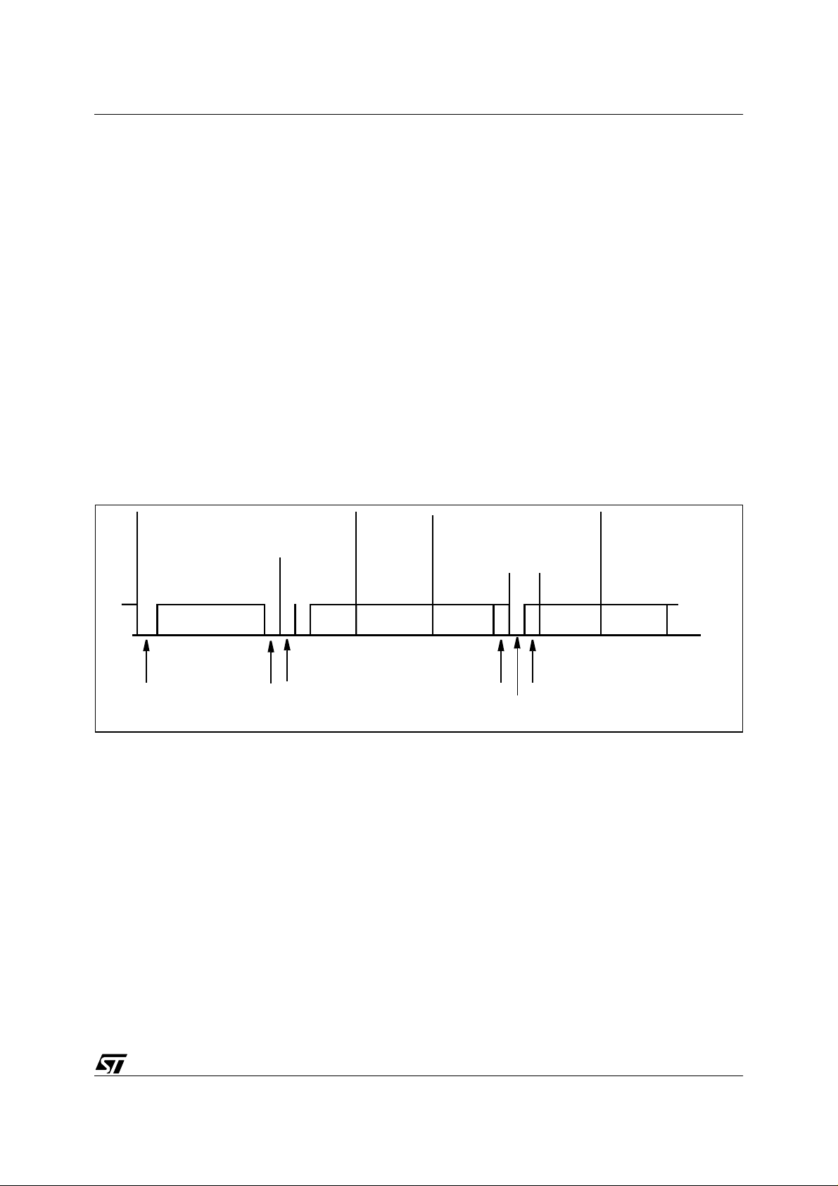
If the bus is already in use when a cel l requests i t, the cell waits u ntil the end of the curr ent
transmission. Then, all the nodes that are ready to transmit begin their transmission. If a dom-
inant and a recessive bit are sent in the meantime, the first one erases the second. This
causes the cell that is sending the recessive bit to lose the arbitration and switch to Reception
mode. This way, messages with the highest identifiers are sent before the others. This mechanism also prevents collisions occurring on the bus, which saves bandwidth. This is referred to
as non-destructive bitwise arbitration.
Figure 7. Arbitration example: node 1 win s
Node 1
Node 2
Node n
CAN Bus
Recessive
Dominant
10/100
Page 11

ST7 pCAN PERIPHERAL DRIVER
1.4.2 Message Acknowledgement
Any cell having received a message correctly, regardless of the result of the acceptance test,
must acknowledge it by sending a dominant bit during the ACK slot of the current frame, thus
overwriting the recessive bit sent by the current transmitter.
1.5 ERROR MANAGEMENT
The Error Management System of the CAN protocol i s proof of the protocol’ s robustness. T his
system provides a way to automatically distinguish permanent failures from sporadic errors. It
can lead to self-disconnection of a failing node from the bus. This feature i s named Error Con-
finement. An error is defined as a violation of one of the protocol’s rules. It can happen after
one of following events:
Bit error:
–
A transmitter detects a difference between the actual bus state and what it
sends.
–
Acknowledgement error:
Stuffing e rror:
–
–
CRC error:
–
Format error:
More than five identical bits were received consecutively.
The CRC received does not match the calculated CRC.
One of the f ixed -format fi elds ( CRC delimi ter, ACK delimi ter, End Of Frame )
A frame is not acknowledged (ACK slot recessive).
does not have the expected format.
An Error frame is immediately sent by all the cells that have detected an error on the bus. Note
that the Error frame does not yield to the Stuffing r ule. Upon reception of this frame, al l cells in
the network detect a Stuffing error and react by sending an Error frame. The dominant state of
the bus caused by the occurrence of an error can last at most 12 bits (case when a node detects the error only at the end of the error flag).
The Error Confinement system is based on two counters:
– A TransmissionError counter (TEC)
– A ReceptionError Counter (REC)
The rules handling the counters are basically the following:
– When an emitting node detects an error, it increments its TEC and sends an error frame.
– When a receiving node detects an error it increments its REC and sends an error frame.
– When a transmission is successful, the TEC counter is decremented.
– When a reception is successful, the REC counter is decremented.
Note: The complete set of rules is quite complicated taking into account the possibility of receiving over-
load frames, etc. Consequently, it’s beyond the scope of this document. This docume nt describes
the basic reactions of the cell. For more information, refer to the original Robert Bosch GmBH document or to the ISO 11898 norm.
The behaviour of the cell con cerning the sta te of the counters is sho wn in the following dia gram.
11/100
Page 12
ST7 pCAN PERIPHERAL DRIVER
Figure 8. CAN Error States
Error Active
128 blocks of 11 successive recessive b its
TEC<127 and REC<127
Bus Off
When both counters contain values between 0 and 127, the CAN node is in Error Active
state, which means that it can send and receive normally. If it detects an error, it will send Active Error flags.
When one of the two c ount ers rea ches a value bet ween 12 8 and 2 55, th e node is in Error
Passive state. It will go on receiving and sending normally but will only be authorized to send
Passive Error flags. Therefore, if this node causes trouble by sending unjustified Error frames,
it will not disturb the network for too long.
When one of the counters reaches a value over 255 ( i.e. it overf lows), the CAN node enters
Bus Off state. It is then physically disconnected from the bus. It can go back to Active mode
if it successfully detects 128x11 consecutive recessive bits on the bus.
TEC >255
TEC>127 or REC>127
Error Passive
1.6 ST7 PCAN PERIPHERAL
1.6.1 Main Features
The ST7 pCAN peripheral implements a CAN 2.0B passive protocol. This means that extended frames are recognized and acknowledged, but cannot be saved nor processed by the
microcontroller.
– The pCAN peripheral is based on three 10-byte hardware buffers that can be used either
for transmission or reception. They are prioritized in the increasing priority order 1 to 3 for
transmission and 3 to 1 for reception. Each buffer has a control register indicating if a job is
pending, if new data has been received or if the buffer is currently being written/read. A bit
in this register is used to lock the buffer for transmission (See ST72511 datasheet p.116).
– The baud rate is programmable up to 1 Mbps. The length of the bit synchronisation fields is
also programmable. The baud rate is configured by setting three values: the size of time
quanta (in clock ticks) and the length of the two synchronization segments (in time quanta).
See ST72511 datasheet p.114, Baud Rate Prescaler Register and Bit Timing Reg ister.
12/100
Page 13

ST7 pCAN PERIPHERAL DRIVER
– Two 11-bit filters and two 11-bit masks are used for hardware filtering with identifier/iden-
tifier-range definition. The masks define which bits of the filters are to be ignored and which
are to be tested. Any message whose identifier does not match will not be saved in the buffers.
– The cell automatically enters Low Power mode after the reception of 20 recessive bits, or
Standby state on command.
– The pCAN peripheral can wake-up the ST7 microcontroller from HALT mo de. See Section
2.1.3.2 "Waking-up from HALT Mode" to learn how.
– The CAN Erro r Confinement feature, as defined by the CAN protocol, is fully implement-
ed, with read-only access to the counters and maskable interrupts on state changes. Once
in Bus Off state, the cell automatically returns to Bus Ac tiv e state if it has detected 128x11
recessive bits on the bus (see Section 2.1.3.1 "Controlling Status Changes"). See note on
Section 2.1.3.2 "Waking-up from HALT Mode" to see how the driver can provide you with full
control over the bus-off to bus-active transition.
– The three Send/Receive buffers, filters, masks and counters are mapped at a unique ad-
dress space, allowing efficient software access.
1.6.2 Cell Behaviour
In Standby state, the node monitors the bus in order to detect a dominant pulse that could generate an interrupt (See ST72511 datasheet p.112, Interrupt Control Register, SCIE bit).
When the RUN bit of the Co ntrol Status Regi ster is set (See ST 72511 datasheet p.113), the
cell leaves
standby
mode. It then enters
resynchronization
mode before it r eally starts running.
If the WKPS bit of the Control/Status Register is set, then the cell will send a dominant pulse
when it wak es up . You c an choos e bet ween two resyn chron ization duration s: 11 recessiv e
bits if the FSYN bit of the C SR is set or 128*11 recessive bi ts if not (See ST72511 datasheet
p.113).
If the cell resynchronizes after leaving bus-off st ate, it will wait 128*11 recessi ve bits, whatever
the value of FSYN may be.
To send data, a buffer has to be selected first by writing to the Page Selection Register (See
datasheet p. 114). Then it has to be locked for transmission by setting the LOCK bit in the
Buffer Control/Status Register (See datasheet p.116: LOCK bit and RDY bit). Then data can
be written in the buffer registers: identifier, data length code, data bytes. Writing in the seventh
data register starts transmission.
Received data is automatically stored in one of the buffers configured for reception (LOCK bit
reset) each time a message identifier matches the hardware filters of the pCAN cell, and provided th at thi s b uff er is m ark ed as fre e (R DY b it res et. Se e dat ashe et p .116: L O CK bit a nd
RDY bit). The masks/filters can be configured through the Filter/Mask High/Low Registers
(See datasheet p.117).
13/100
Page 14
ST7 pCAN PERIPHERAL DRIVER
Any event (succ essfu l transm ission , data recep tion, er ror, s tate ch ange , overru n) can generate a maskable interrupt. The Interrupt C ontrol Regis ter (see datasheet p.112) al lows you to
set/reset these masks. Note that each buffer has its own reception interrupt, allowing the data
to be saved rapidly.
Note: For further, more detailed explanations, please read the ST72511R/ST72512R/ST72532R Datash-
eet, downloadable from the ST web site, http://mcu.st.com.
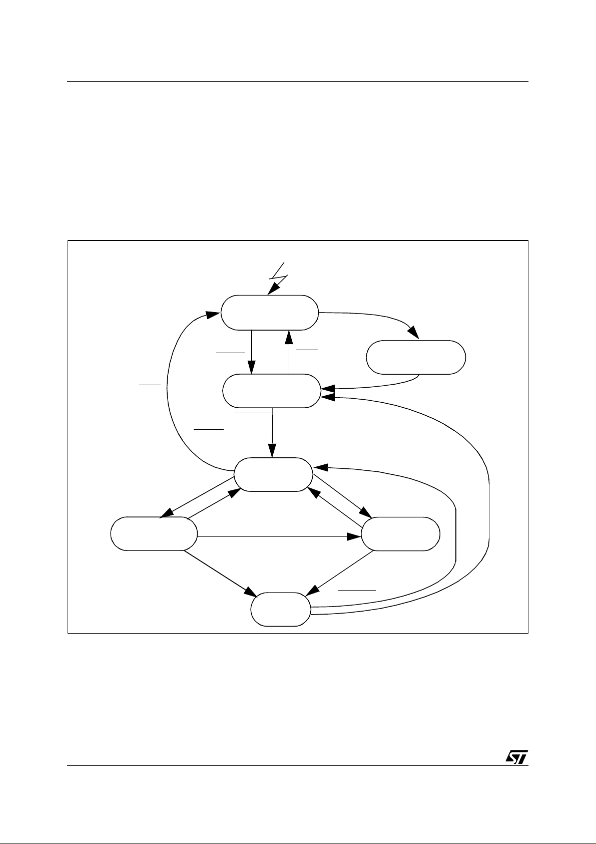
Figure 9. ST7 pCAN State Diagram
RESET
RUN
Transmission
RUN
& WKPS
FSYN & BusOFF
(FSYN
TX Error
| BusOFF) & 128*11 Recessive bits
TX OK
Standby
RUN
Resynchronisation
& 11 Recessive bits or...
Idle
RX OK
Arbitration lost
RUN & WKPS
Wake-up Pulse
Generation
Start of frame
Reception
RX Error
14/100
BusOFF
Error
BusOFF
Page 15

ST7 pCAN PERIPHERAL DRIVER
2 CAN DRIVER
To quickly start developing your own CAN applications using the ST7 pCAN peripheral, STMicroelectronics provides you with a driver. The source code (can.h and can.c) is given as an example, and can therefore be used as provided or be modified to fit specific needs.
There are two customizatio n files which make the dr iver’s f unctionality flexib le a nd able to
meet a wide range of needs.
The entire processing is interrupt driven, so no polling is required. The application is notified of
CAN events through function calls from the interrupt routine.
To immediately use the driver, without modifying its structure, see Section 2.2 "How to Use the
CAN Driver: A Dem o Applicat ion" .
The following sections will explain the details of the driver architecture and describe all the
functions and data types implemented in the software.
2.1 USER INTERFACE
2.1.1 Files Furnished
The driver consists of five files:
– can.c. Driver function definitions and internal data types. This file may not be modified.
– can.h. Header file of can.c. This file may not be modi fied.
– can_hr.h. Hardware description (register mapping of the ST7 MCU memory space). This file
is hardware dependent and must not be modified.
– can_custom.c. Frames of customization functions. They are called (some optionally) by the
driver to notify the application of events when some user-specific processing is required (for
example on reception of data). This file has to be completed by the user.
– can_custom.h. Contains a pre-processor directive list (
#define
types) which allows user
customizations to be taken into account at compilation time. T his file has to be m odified by
the user.
2.1.2 Architecture
The cell is statically configured with one transmi ssion buffer and two reception buffers, which
reduces the need for processor responsiveness in reception.
For the same purpose, a 3-message deep transmission FIFO is implemented. It is not accessible by the user, and is automatically managed by the software.
The entire processing is interrupt driven. The user can choose which interrupts are to be taken
into account and which are not, due to the compilation options in can_custom.h. Some interrupts request an immediate answer from the application, e.g. a reception event. To avoid
having the user modify the interrupt routine (in can.c), the routine calls one of the notification
15/100
Page 16
ST7 pCAN PERIPHERAL DRIVER
functions defined in can _custom. c on c ertain ev ents . Th e user only has t o enter these func tions according to his needs before compiling the software.
2.1.3 Principle of Use
During compilation, the values of the hardware control registers are calculated by the preprocessor according to the compilation options selected in can_custom.h.
If the software filtering feature is enabled, the values of accepted identifiers hav e to be entered
by the user as a list in can_custom.h (See “Filtering” on page 29)
The functions in can.c are compiled or not, according to the selected
unwanted ones are simply left as comments).
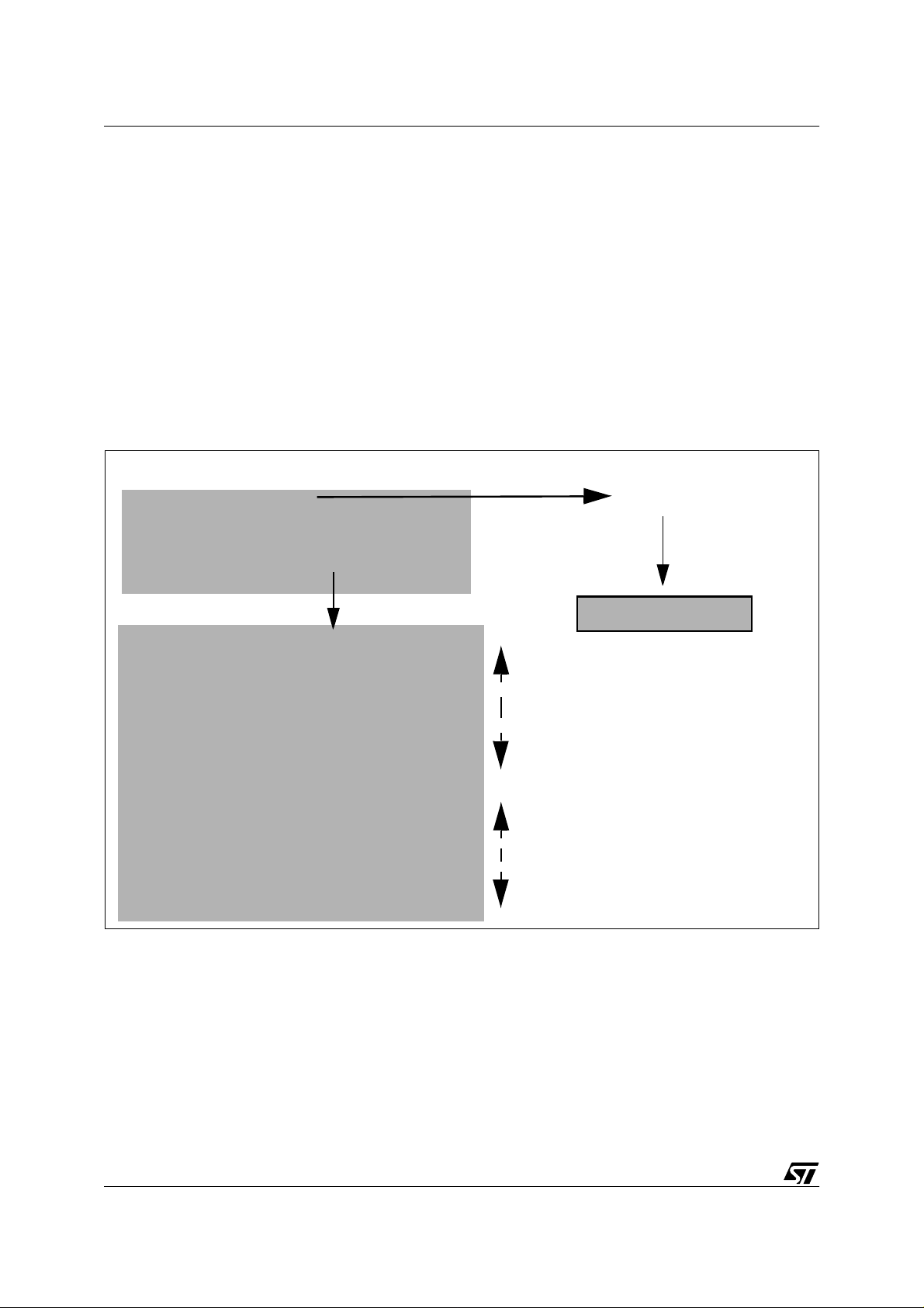
Figure 10. Driver Customization System
CAN_CUSTOM.H FILE
#define INIT_BRPR 0x11
...
#define STATUS_CHANGE_NOTIFICATION
...
//#define DEBUG
CAN_CUSTOM.C FILE
#ifdef STATUS_CHANGE_NOTIFICATION
void CAN_Bus_Passive_Notification(void)
{
//To implement if defined
}
#endif
...
...
#ifdef DEBUG
void CAN_Overrun_Notification(void)
{
//To implement if defined
}
#endif
Compilation
Compiled
Not Compiled
BRPR Reg ister
ST7 Registers
#define
0x11
directives. (The
Compilation
During the first initialization (performed using the CAN_First_Init function), the periph eral’s
registers are written with the values defined at compilation time, the transmission FIFO is initialized and the cell starts (a wake up by bus can be chosen).
Then:
– The
CAN_Transmit_Request
function initiates a transmission which begins with an in-queuing of the message to be sent. Then, hardware buffer no.1 (the static transmission buffer ) is
filled according to hardware requirements. (See Section 1.6.2 "Cell Behaviour").
16/100
Page 17

ST7 pCAN PERIPHERAL DRIVER
– The
CAN_Switch_Off
and
CAN_Sleep
functions are used to switch the cell to Standby mode.
The first function kills any pending jobs and erases all data in the reception buffers, even if
the data is unread. The second function is executed the same way as long as no work is in
progress, the transmission FIFO is empty and all reception buffers have already been read.
These two functions also define the way the cell will be woken-up: either by bus or by software (by enabling or disabling the corresponding interrupt). They can help you to manage
status changes by controlling the transition between Bus Off and Bus Active states (See Sec-
tion 2.1.3.1 "Controlling Status Changes").
–
CAN_Switch_On
resets the cell and returns to RUN mode. It can also place the cell in a state
waiting for a dominant pulse to be woken-up.
–
CAN_Get_Status
–
CAN_Get_TEC
–
CAN_Get_REC
returns the current status of the peripheral (run, standby, error passive...)
returns the current content of the transmission error counter.
returns the current content of the reception error counter.
2.1.3.1 Controlling Status Changes
Your application can be notified by the dri ver when the error state of the cell changes . (See
“Compilation Options” on page 25). If you don’t want the microcontroller to directly resynchro-
nize after leaving bus-off state for example, you can call the CAN_Switch_Off function from inside o f the C AN _Bu s _Off_Notifica ti on fu nc tion ( Se e “C an_cus tom.c Fil e” on page 26), then
perform any operations you want before calling the CAN_Switch_On function to restart the peripheral.
2.1.3.2 Waking-up from HALT Mode
If you want to switch the ST7 to HALT mode and have it woken-up by the CAN, the correct interrupt routine must be enabled. Before switching to HALT mode, call the CAN_Sleep or
CAN_Switch_Off function with the BUS_WAKEUP parameter that is used to enable the CAN
interrupt on the bus dominant state while in Standby state.
Then, enter the CAN_Dominant_Bit_Reception_Notification function to customize the waking
up of the microcontroller.
Note: See ST72511 datasheet p.37 for more information about HALT mode.
2.1.4 Interrupts (ITs)
Once the interrup t r outin e is enter ed, th e f irst thi ng you wan t t o kno w is “Wha t t rigger ed the
event?” Priority is then given to reception if more than one IT has occurred simult aneously, unless the DEBUG compilation option was set. In this case, the Error ITs are processed first.
– In the event of a Transmission IT, the driver tries to send the following message in the queue,
if it’s not empty. The driver then notifies the application of the event before leaving the routine.
17/100
Page 18
ST7 pCAN PERIPHERAL DRIVER
Figure 11. Transmission IT Proced ure
What
you
see
Application
3
Notification
Error notification, only
5
if DEBUG defined
ST Driver
4
Fills buffer
with next data
Driver
Processing
1
IT
2
Clears flags
ST7 Hardware
Successful
Transmission
CAN Bus
– In the event of a reception IT, after having found which buffer is i nvolved, the dri ver performs
an optional software filtering, then noti fies the application. If the cell r eceived a remote frame,
the CAN_Remote_Reception_Notification function is called. Otherwise, if the cell received
data, the CAN_Request_Buffer function is called to request a buffer from your application.
After the buffer is filled, the dr iver calls the CAN_Data_Reception_Notification function to notify you that the data is ready. If the DEBUG option is set, the CAN_Reception_Status function is called just before leaving the IT routine, which passes the status of the reception
processing procedure (Error, Success...) as a parameter. This is used to detect the causes
of any problems. See “Can_custom.h File” on page 24 for more information about notification
routines.
Next
Transmission attempt
Figure 12. Reception IT Procedure
What
you
see
Driver
Processing
18/100
1
Notification:
2
Data or Remote
IT
Successful
Reception
3
Application
Notification
4
(case data)
5
ST Driver
Save data in software buffer
(case data) + clears flags
ST7 Hardware
CAN Bus
Buffer free for
reception
next
Error notification
Only if DEBUG defined
Page 19

ST7 pCAN PERIPHERAL DRIVER
– Error ITs are only processed if the DEBUG option was chosen in can_custom.h. Then, the
application is notified of any other events through function calls. (Functions entered in
can_custom.c).
2.1.5 User Interface Description
This section describes the user interface in a “black-box” way. The parameters and the return
values of the function declared in can.h and can_custom.h are described in this section. For a
complete description of the algorithms and internal data type variables, please see Section 3
"Detailed Description".
2.1.5.1 Data-type Variables
CAN_Buffer -type variables
typedef struct CAN_Buffer{
u16msg_identifier;
CAN_Data_Size data_size;
u8 CAN_msg_data[CAN_MAX_DATA_SIZE];
CAN_Bool buffer_rw;
CAN_Bool buffer_free;
}CAN_Buffer;
Software repres enta tion of C AN data . The trans latio n into hardwar e buffers is pe rform ed b y
the driver.
A variable of this data-type must be passed to the driver each time it is requested by the
CAN_Request_Buffer notification function (See “Functions called unconditionally” on
page 26). Otherwise, data in the hardware buffer will be lost.
A pointer to this structure i s also us ed as param eter of the CAN_Trans mit_Req uest function
(See “Functions” on page 21).
–
msg_identifier:
2 bytes field containing the identifier of the CAN message. The identifier is
stored in the 12 most significant bits. The 4 least significant bits MUST be zero. The u16
type means 2 bytes unsigned variable and is defined in lib.h.
–
data_size:
1 byte field containing the length of the data in the m essage (in bytes). The
CAN_Data_Size type is an enum type (See below for its description).
–
CAN_msg_data
: array of 8 bytes containing the data to be sent. The u8u16 type means 1
byte unsigned variable and is defined in lib.h.
–
buffer_rw
: this boolean variable is to be us ed as a flag to prevent simultaneous writing/
reading on the structure. It is checked and modified by the driver each time an operation
is being performed on the buffer. If CTRUE, the structure will not be read or written. If
CFALSE, it can be used. Always check/modify this variable in your application for this purpose.
–
buffer_free
: boolean variable used to mark if the data in the buffer can be overwritten or
not. It has to be used as the s ecurity by the user’s application. If C FALSE , the driver will
refuse to perform any write operation on the data in the structure and return an error code.
19/100
Page 20

ST7 pCAN PERIPHERAL DRIVER
If CTRUE, the data can be modified. Take care to check and/or initialize it before passing
a buffer to the driver.
Init_Data -type variables
typedef struct {
u8 brpr_init;
u8 btr_init;
u8 fhr1_init;
u8 flr1_init;
u8 mhr1_init;
u8 mlr1_init;
u8 fhr0_init;
u8 flr0_init;
u8 mhr0_init;
u8 mlr0_init;
u8 }Init_Data;
This structure contains the value of registers tha t can be reinitialized when switching on the
cell after a passage in Standby state (see Section 2.1.5.2 "Functions", CAN_Switch_On).
It is used for hardware initialization.
–
brpr_init
: value of the CANBRPR register (set length of a CAN time quantum in number of
CPU clock ticks). S ee “Bit timing” on page 9.
btr_init
–
: value of the CANBTR register (length of both time segments 1 and 2 in number of
time quanta). See “Bit timing” on page 9.
fhr1_init
–
–
flr1_init
–
mhr1_init
mlr1_init
–
–
fhr0_init
–
flr0_init
–
mhr0_init
mlr0_init
–
: value of Filter 1 High Register.
: value of the Filter1 Low Register.
: value of the Mask 1 High Register.
: value of the Mask 1 Low Register.
: value of Filter 0High Register.
: value of the Filter 0 Low Register.
: value of the Mask 0High Register.
: value of the Mask 0Low Register.
Enum -type variables
The names of the variables are in principle self-explanatory.
typedef enum
{DLC0,DLC1,DLC2,DLC3,DLC4,DLC5,DLC6,DLC7,DLC8,REMOTE_FRAME}CAN_Data_Size;
Possible values of the CAN _Mess age data_size fiel d (See “CAN_Buffer -type variables” on
page 19)
typedef enum
20/100
Page 21

ST7 pCAN PERIPHERAL DRIVER
{CAN_RUN,CAN_STANDBY,CAN_BUS_ACTIVE,CAN_BUS_PASSIVE,CAN_BUS_OFF}CAN_Status;
Describes the different states of the cell.
typedef enum {CFALSE=0,CTRUE=1}CAN_Bool;
Custom Boolean type variable.
typedef enum {BUS_WAKEUP,SOFT_WAKEUP}WakeUp_Cause;
Possible parameters of the CAN_Sleep and CAN_Switch_Off functions. (See Section 2.1.5.2
"Functions".)
typedef
enum{CAN_SLEEP_ERROR,CAN_SLEEP_SUCCESS,CAN_SWITCH_ON_SUCCES,CAN_SWITCH_ON_FA
ILURE}CAN_Switch_Error;
Possibl e val ues r etu rned by CA N_S leep , CAN _Sw itc h_Off and C AN _Swit ch_ On fun cti ons
(See Section 2.1.5.2 "Functions")
typedef enum {CAN_INIT_SUCCESS,CAN_INIT_FAILURE}CAN_Init_Error;
Possible values returned by CAN_First_Init function (See Section 2.1.5.2 "Functions")
typedef enum
{CAN_TRANSMIT_SUCCESS,CAN_TRANSMIT_FAILURE,CAN_TRANSMIT_NO_MSG,CAN_FIFO_FULL
,CAN_TRANSMIT_BUFFER_FULL,CAN_TRANSMISSION_ERROR_IT}CAN_Transmit_Error;
Error codes used in Transmission functions.(See Section 2.1.5.2 "Functions")
typedef enum
{CAN_RECEIVE_SUCCESS,CAN_RECEIVE_REMOTE,CAN_ILLEGAL_IDENTIFIER,CAN_FILTERING
_FAILURE,CAN_RECEIVE_FAILURE,CAN_BUFFER_IN_USE,CAN_NO_BUFFER,CAN_RCV_BUFFER_
NOT_READY}CAN_Receive_Error;
Error codes used in Reception functions. (See Section 3.2.2 "Internal Routines").
Note: With some compilers, an option is used to define the size, in bytes, of enum-type variables. We rec-
ommend selecting 1 byte, if possible, to save memory space.
You can see in which case the different error codes are returned by the functions by studying
the flow charts in Section 3.2.2 "Internal Routines" for internal functions and Section 3.1 "User
interface functions" for user interface functions.
You als o fin d th is info r ma tion i n t he a rr ays o f Section 2.1.5.2 "Functions" for user-interface
routines and Section 3.2.2 "Internal Routines" for internal routines.
2.1.5.2 Functions
CAN_Init_Error CAN_First_Init(void):
Input -Output Error status
21/100
Page 22

ST7 pCAN PERIPHERAL DRIVER
CAN Cell Power-on initialization routine.
During its execution, all registers are initialized with values entered in can_custom.h
Description
Comments Calls CAN_Init() (See Section 3.2.2 "Internal Routines")
or calculated from the compilation options chosen
It initializes the transmission queue.
This function must be called in the main routine prior to any use of the CAN cell.
Possible return values: CAN_INIT_FAILURE and CAN_INIT_SUCCESS.
void CAN_It_Dis(void):
Input -Output -Description Disables all CAN interrupts.
Comments --
CAN_Status CAN_Get_Status (void):
Input -Output Current status of the cell
Retrieves the current status of the CAN cell.
Description
Comments Useful if the STATUS_CHANGE_NOTIFICATION option is enabled in can_custom.h
Possible return values: CAN_STANDBY, CAN_BUS_PASSIVE, CAN_BUS_OFF
and CAN_BUS_ACTIVE following the current state of the cell.
u8 CAN_Get_TEC(void):
Input -Output Value of the TECR register (Transmission Error Counter)
Description Returns the value of the TECR
Comments --
u8 CAN_Get_REC(void):
Input -Output Value of the RECR register (Reception Error Counter)
Description Returns the value of the RECR
Comments --
CAN_Switch_Error CAN_Switch_Off(WakeUp_Cause):
Input Chip Wake-up function: BUS_WAKEUP or SOFT_WAKEUP
Output Error status
22/100
Page 23

ST7 pCAN PERIPHERAL DRIVER
Puts the CAN node into Standby state.
This function aborts any pending transmissions and does not wait for the reception
buffers to be read. Then, it resets the driver in the same state as after power-on initialization.
If BUS_WAKEUP is selected, the next dominant bit detected on the bus will restart
Description
Comments Calls CAN_Clean (See Section 3.2.2 "Internal Routines".)
the cell. If SOFT_WAKEUP is selected, the cell will not take the bus state int o account. It can only be woken up by the CAN_Switch_On function.
Possible return value: CAN_SLEEP_SUCCESS or CAN_FATAL_ERROR (if the
RUN bit fails to reset after a time out or if the CAN_Clean function fails).
There is a time out mechanism implemented in this function (about 30ms), waiting for
the RUN bit to be actually reset. So if your application uses the watchdog REFRESH
IT BEFORE calling the function
CAN_Switch_Error CAN_Sleep (WakeUp_Cause):
Input Chip Wake-up function: BUS_WAKEUP or SOFT_WAKEUP
Output Error status
Puts the CAN node into Standby state.
Returns CAN_SLEEP_ ERROR if a tra nsmiss ion r equest is pending, or i f a hardware
receptio n bu ff er is still un s av e d.
Description
Comments This function will not reset the CAN node.
Possible return values:
CAN_SLEEP_ERROR if there are jobs pending in the hardware registers,
CAN_FATAL_ERROR if the RUN bit fails to reset after a time out,
or CAN_SLEEP_SUCCESS
CAN_Switch_Error CAN_Switch_On(Init_Data_Ptr,CAN_Bool):
Input
Output Error status
Description
Comments Calls CAN_Init (See Section 3.2.2 "Internal Routines").
Pointer on an Init_Data structure (See Section 2.1.5.1 "Data-type Variables"),
Boolean (CTRUE, CFALSE)
Puts the CAN node into Active state
The Boolean is used to transmit a dominant pulse (CTRUE) or not (CFALSE) upon
wake-up.
The bit timing and the mask/filter parameters can be reinitialized in this function. In
most cases, the cell will be initialized the same way as in the Power-on sequence.
So, you can re-use the first_init_data structure is declared in can.h.
Possible return values: SWITCH_ON_SUCCES and SWITCH_ON_FAILURE.
CAN_Transmit_Error CAN_Transmit_Request(CAN_Buffer*):
Input Pointer to the CAN message to be sent
Output Error status
23/100
Page 24

ST7 pCAN PERIPHERAL DRIVER
Puts a buffer into the transmission queue, and may request an immediate transmission if the queue is empty.
The buffer_rw field has to be CFALSE before passing it to the function. It is immediately marked as CTRUE after entering the routine. In case of an error, during the execution, this parameter is reset to CFALSE before exiting. Else it is only reset by
Description
Comments
CAN_Fill_Transmission_Buffer (See Sec tion 3.2.2 "Internal Routines").
Possible return values:
CAN_TRANSMIT_FAILURE if the cell is in stand-by,
CAN_FIFO_FULL if the 3 messages deep FIFO is full,
CAN_TRANSMIT_FATAL if CAN_Fill_Transmission_Buffer fails,
or CAN_TRANSMIT _ SUC CESS o th e r wise.
This function MUST NOT be interrupted, so protect it with SIM and RIM statements
when used OUTSIDE the notification functions of CAN_custom.c!
Calls CAN_Init_Queue and CAN_Fill_Transmission_Buffer (See Section 3.2.2 "Inter-
nal Routines")
2.1.5.3 Constants
Those constants are defined internally, but are made visible to the user because they may be
useful.
extern const Init_Data first_init_data
This is the initialization data structure that is used on power-on. It is made visible to allow you
to pass it to the CA N_Switch_On function when you do no t want to modi fy the param eters it
contains. (See Section 2.1.5.1 "Data-type Variables")
extern const u16 i_filters[];
This is the array of filters used to perform software filtering on incoming messages. The maximum number of identifiers stored is 127 (See “Filtering” on page 29). It is made visible in case
you would like to link the behaviour of your application upon reception of a message with the
offset of the id entifier in the array (ma naging an arr ay of pointe rs to func tions fo r example) .
One can of course imagine other applications.
2.1.5.4 Can_custom.h File
The preprocessor directive s used to configure the har dware an d to customize the driver are
located in this file .
Cell Configuration Values
#define INIT_BRPR 0x00
#define INIT_BTR 0x00
These values are used to initialize bit timing registers. (See Section 2.2.2.1 "Bit Timing").
/*Masks & filters*/
#define INIT_FHR0 0x00
24/100
Page 25

ST7 pCAN PERIPHERAL DRIVER
#define INIT_FLR0 0x00
#define INIT_MHR0 0x00
#define INIT_MLR0 0x00
#define INIT_FHR1 0x00
#define INIT_FLR1 0x00
#define INIT_MHR1 0x00
#define INIT_MLR1 0x00
These values are used to initialize hardware filters and masks. (See “Filtering” on page 29).
Compilation Options
//Start options
//#define WAKE_UP_PULSE
#define RUN_ON_START_UP
You may decide whether or not to include these options in the code.
If enabled:
– WAKE_UP_PULSE enables the cell to send a domi nant bit when leaving Standby mode.
– RUN_ON_START_UP starts the cell in the Initialization function CAN_First_Init. If not en-
abled, make sure that a dominant bit detected on the bus can make the cell start. To do
this, complete the
CAN_Dominant_Bit_Reception_Notification()
function in can_custom.c
in calling CAN_Switch_On.
//#define FILTERS_ENABLED
//#define INIT_FILTERS {}
These options are used for software filtering.
Select both of them if you want to use the feature.
If selected, en ter the li st of ide ntifi ers to b e accep ted b etwee n the c urly brac es as s hown i n
“Software Filter Configuration” on page 30.
Enabling one of the following options implies modifying the corresponding function in the
can_custom.c file:
//#define STATUS_CHANGE_NOTIFICATION
This option is used to monitor status changes (active/passive/bus-off). Setting this option will
change th e pri ority ord er in w hic h the i n terru pt s are t ak en i nt o ac c ount. T he i nte rrupts con cerning status change will be checked first, before considering reception and transmission interrupts. It will also allow compilation of the cor responding notificatio n function s
(CAN_Bus_Passive_Notification, CAN_Bus_Acti ve_Notification, CAN_Bus_Off_Notification).
To use the Error Notification functions (called when an Error IT is received), enable:
//#define DEBUG
25/100
Page 26

ST7 pCAN PERIPHERAL DRIVER
If DEBUG is defined, you can then chose to add the following options:
//#define GENERAL_RECEPTION_ERROR
All reception errors trigger an interrupt. You CANNO T us e this option and the
Notification
function together because both use the same IT flag. This option does not exclude
Status Change
the bus Wake-Up feature.
//#define SIMULTANEOUS_EMISSION_RECEPTION
Only if Debug is also defined.
This function is used for forcing the cell to simultaneously send and receive any message it is
ordered to transmit to check the hardware integrity of the CAN transceiver and controller.
2.1.5.5 Can_custom.c File
This is a source file you have to complete, to allow your applicati on to react on hardware
events as they happen. An example of implementation is given in Section 2.2.3 "Implementing
the Notification Functions".
Functions called unconditionally
CAN_Buffer* CAN_Request_Buffer(u16 ident_of_message)
This function is called unconditionally when a new data message is available in the hardware
buffer of the cell. This function has to be completed to return a pointer on a buffer structure. To
ignore it, return NULL. To help you to manage your reception buffer(s), the ID of the message
is passed as a parameter.
void CAN_Remote_Reception_Notification(u16 ident_of_remote)
This function is called unconditionally when a r emote message has been saved in a hardw are
buffer. Its ID is passed as a parameter for a quick answer.
void CAN_Data_Reception_Notification(u16 message_ident)
This function is called unconditi onally when a data message has been successfully saved i n a
software buffer supplied by the application. Its ID is passed as a parameter.
void CAN_Transmission_Notification(void)
This function is called unconditionally upon the successful transmission of a message.
Functions called conditionally
The following functions are called only if the corresponding option is set in can_custom.h.
void CAN_Dominant_Bit_Reception_Notification(void)
This function is called upon reception of a dominant bit while in Standby mode, if the
RUN_ON_STARTUP option was not defined in can_custom.h. The corresponding interrupt
will be accepted only once. Then its acceptance flag will be cleared.
void CAN_Bus_Passive_Notification(void)
void CAN_Bus_Active_Notification(void)
26/100
Page 27

ST7 pCAN PERIPHERAL DRIVER
void CAN_Bus_Off_Notification(void)
These functions are called after a status change.
Option: #define STATUS_CHANG E_NOTIFICATION
void CAN_General_Reception_Error_Notification(void)
This function notifies the application of any hardware reception errors.
Option: #define DEBUG and #define GENERAL_R ECEPTION_ERROR
void CAN_Reception_Status(CAN_Receive_Error status)
This function is called after a reception attempt and returns the status of the software
processing (See “Enum -type variables” on page 20).
Option: #define DEBUG
void CAN_Overrun_Notification(void)
This function notifies the application of any overruns.
Option: #define DEBUG
void CAN_Transmission_Error_Notification(CAN_Transmit_Error status)
This function notifies the application of any hardware transmission errors.
Option: #define DEBUG
2.2 HOW TO USE THE CAN DRIVER: A DEMO APPLICATION
In this section, we will des cribe step-b y-step the c onfigurati on and pr ogrammi ng of a s imple
test application using the ST7 CAN driver.
2.2.1 Application
First of all, we mus t define how th e applicati on will lo ok, i.e. w hich m essages our cell w ill be
able to send, which ones it will accept to receive, and how it will behave when sp ecific messages are received.
Let’s imagine the following:
– The cell has to run immediately after power-on, and does not have to send a dominant pulse.
– Every 15 ms the cell must send the contents of the ST7 A/D Converter data register. The
identifier (ID) of this message could be, for example, 0x402.
– Upon reception of a remote frame (see Section 1.2 "CAN Frame") it must reply with the trans-
mission of a given message. The ID of the remote frame could be, for example, 0x500 (consequently, the ID of the answer will also be 0x500).
– Upon reception of a given data item, the CAN cell must shut down. This ID of the message
could be 0x600, and the data item 0xFF, in its first data byte.
– The cell is supposed to receive 3 other data messages coming from other nodes. Let’s im-
agine they are identified by 0x127, 0x311, 0x3A5.
27/100
Page 28

ST7 pCAN PERIPHERAL DRIVER
– Identifiers may exist on the bus that do not concern our cell.
2.2.2 Cell Configuration
Open then the can_custom.h file. You can see the two first lines of code:
//#define WAKE_UP_PULSE
//#define RUN_ON_START_UP
According to ou r requi reme nts (Se e Sec tion 2 .2.1 "Ap plica tion"), w e only want to define the
RUN_ON_STARTUP option.
So modify the code the following way:
//#define WAKE_UP_PULSE
#define RUN_ON_START_UP
2.2.2.1 Bit Timing
First of all, we have to decide the speed of our network. Let’s say, for example, 250 kilobaud.
Look in your can_custom.h file. You see the following code:
#define INIT_BRPR 0x00
#define INIT_BTR 0x00
The following two registers define the bit timing in the cell.
The BRPR regi ster c onta ins the size o f t ime qu antum , i n num b er of clo ck tic ks, in a bit f ield
named BRP (See Section 1.3.2 "Bit timing").This field ranges from 0 to 63. The true value for
a time quanta is then BRPR+1.
The BTR register contains the size of the two synchronization segments in time quanta, in two
different bit fields: BS1 and BS2(“). BS1 ranges from 0 to 7and BS2 from 0 to 3. The actual
length of bit segments in time quanta is then BS1+1 and BS2+1.
You must always chose BS1>BS2, so that the sampling point takes place in the second half of
the bit.
Use the following formula:
fbus Bauds()
------------------------------------------------------------------------ -=
1BRP+()3BS1 BS2++()×
fcpu Hz()
For example, in our case, fcpu = 8 MHz.
So, fbus = fcpu/32.
We have then the following possibilities:
28/100
BTR+1 BS1+BS2+3
216
Page 29

ST7 pCAN PERIPHERAL DRIVER
BTR+1 BS1+BS2+3
48
84
Let’s choose, for example, BTR = 3, BS1 = 3, BS2 = 2 (second row).
We have to complete the code:
#define INIT_BRPR 0x03
#define INIT_BTR 0x23
2.2.2.2 Filtering
The driver is able to filter out all messages not needed by the application. First by using hardware filters, and second by using software filters.
Use the hardware filters to eliminate as many identifiers as possible and to avoid further
processing. Use the software filters to elimi nate IDs that are unwanted, but that can not
stopped by the hardware.
Hardware Filter Config uration
Let’s define the values of hardware masks and filters. To do this, we must split the IDs into two
groups:
– 0x127, 0x311 and 0x3A5, on one hand; and,
– 0x500 and 0x600 on the other.
Note: When grouping the IDs, try to maximize the number of identical bits inside the same group, thus
minimizing the width of the ID ranges accepted by the cell.
Then let’s find the first filter/mask pair (12 bits to be determined):
– 0x500 is written in binary: 101 0000 0000
– 0x600 is written in binary: 110 0000 0000
In the first three bits, only the most significant bit (MSB) of both identifiers is the same, the following two bein g d ifferent. S o, the thr ee MS Bs of the mas k wi ll b e 1 0 0 (m atch, don ’t c are,
don’t care) and the three MSBs of the filter will be 1 and then either 1 or 0.
The following eight bits are identically null. So the last eight bits of the filter will be 0, and the
last eight bits of the mask will be 1 (match required).
The least signi ficant bit (LSB) of t he filter/ma sk is used to s epa rate rem o te fr ames a nd d ata
frames. Here we have a data frame and a remote frame, so it does not have to be checked (1
or 0 into the filter, 0 into the mask).
So we have:
– Filter 1000 0000 0000
– Mask 1001 1111 1110
29/100
Page 30

ST7 pCAN PERIPHERAL DRIVER
Now look at the can_custom.h file:
There are several #define statements, including:
#define INIT_FHRi 0x00
#define INIT_FLRi 0x00
where i is either 0 or 1.
These are the two registers containing hardware filters. In the FHRi register, the 8 MSBs for
the filters are given, and in the second register the 4 LSBs are given followed by 4 zeros.
We have to do the same thing for the mask. First, let’s write 0 for the filter.
Finally we have:
#define INIT_FHR0 0x80
#define INIT_FLR0 0x00
#define INIT_MHR0 0x9F
#define INIT_MLR0 0xE0
Doing the same thing with the other group of identifiers leads to:
#define INIT_FHR1 0x20
#define INIT_FLR1 0x20
#define INIT_MHR1 0xA9
#define INIT_MLR1 0x30
Software Filter Configuration
You need to use software filtering feature if the hardware cannot stop all the undesired identifiers. Look at the following code in can_custom.h:
//SOFTWARE ACCEPTANCE MASKS
//#define FILTERS_ENABLED
//#define INIT_FILTERS {}
To allow software filtering, remove the “//” comment signs, and enter the identifiers between
the parentheses. Please note that the filters must be given in h exadecimal format with four
digits, always terminated by zero, and in increasin g order.
That is to say in our case:
SOFTWARE ACCEPTANCE MASKS: optional choice
#define FILTERS_ENABLED
#define INIT_FILTERS {0x1270,0x3110,0x3a50,0x5000,0x6000}
Note: There can not be more than 127 identifiers in the array.
2.2.3 Implementing the Notification Functions
The cell is now configured, we no longer need to worry about hardware.
30/100
Page 31

ST7 pCAN PERIPHERAL DRIVER
We have then to write our code. Look at the last lines of can_custom.h. There is a set of #define options. As we want to be notified neither of status changes, n or of errors, we will leave
them as comments. Please see Section 2.1. 5.5 "C an_cus tom.c File" for more details about
notification functions.
We must then open can_custom.c, and learn how to use the notification functions that are always compiled.
If your application uses the watchdog timer, you have to write on top of the file:
#include “wdg.h”
to be able to use the refresh function in this module.
The CAN_Request_Buffer function
To retrieve data stored in the ST7 buffers after reception, the application must pass a software
buffer when requested. The following prototype is given in the code:
CAN_Buffer* CAN_Request_Buffer(u16 ident_of_message)
{
//The application must here return a pointer to a physical structure CAN_Buffer
}
This routine is called each time a message has been successfully filtered and is ready to be
used. The pa rame ter pass ed (i.e . the ID of th e recove red me ssage) m ay hel p you mana ge
your buffer(s) more easily.
You then have to create a buffer that will be used to save all data messages.
At the top of the file, add:
////////////////////////////////////////
//VARIABLES/////////////////////////////
////////////////////////////////////////
CAN_Buffer reception_buffer;
And then in the function body:
CAN_Buffer* CAN_Request_Buffer(u16 ident_of_message)
{
reception_buffer.buffer_rw=CTRUE;
return &reception_buffer;
}
The two first lines are used as a s afety device: the driver wil l then be sure that the buffer is not
currently in us e and the da ta in that bu ffer can be overwr itten. In yo ur progr ams, use thes e
fields as keys to know whether the data in a buffer can be accessed and whether it has already
been processed.
Note 1: There is only ONE buffer here that will be used to save all the receive messages. This is only an
31/100
Page 32

ST7 pCAN PERIPHERAL DRIVER
example! You can implement a buffer for each message type, a FIFO of standardized buffers etc.
Note 2: For safe programming, you should systematically verify whether the buffer is not currently being
read/written, and whether the buffer is really free before further processing.
(For specific information concerning the buffer data type, see Section 2.1.5.1 "Data-type Var-
iables").
Remember that one of the received messages may switch off the cell. Once a message is received, we have to check to see if it is this one. This is done using the
CAN_Data_Reception_Notification function.
CAN_Data_Reception_Notification F unction
The CAN_Da ta_R eception_ Notifi cation function is the followi ng protot ype in can_c ustom .c.
The routine is called once the data in a data frame has been saved in the buffer passed in the
CAN_Re ques t_Bu ffer f uncti on. Be fore calli ng the C AN_Sw itc h_on functi on, refres h t he
watchdog (See “Func tions” on pag e 21, CAN_Switch_Off for further explanation). Let’s add
the following code:
void CAN_Data_Reception_Notification(u16 message_ident)
{
if (message_ident==0x6000)//checks the id of message
{
if (reception_buffer.CAN_msg_data[0]==0xFF)//Checks the content of data
{
CAN_Switch_Off(BUS_WAKEUP);
}
}
}
So, if the first data byte of the mes sage whos e identifier is 0x600 contains 0x FF, the cell w ill
switch off and wait for a bus Wake-Up command (a dominant bit).
CAN_Remote_Reception_Notification Function
When a remote frame is received, we must send a message with a 0x500 ID. Let’s do i t i nside
this routine which is called each time a remote frame is received.
The message does not exist yet. As for the buffer, we have to create a variable
message
, by
adding the following code in the file:
////////////////////////////////////////
//VARIABLES/////////////////////////////
////////////////////////////////////////
CAN_Buffer message_to_send_on_request= /
{0x5000,DLC5,{0x00,0x01,0x02,0x03,0x04},CFALSE,CFALSE};
32/100
Page 33

ST7 pCAN PERIPHERAL DRIVER
The structure is initialized here with 0x500 ID, which has a length of five and five data items.
Note: In a real network, the message would not be statically initialized, but would be filled with the content
of one or several variables. The aim here is only to show the way the function can be used.
Then we fill the function with a transmission request:
void CAN_Remote_Reception_Notification(u16 ident_of_remote)
{
if (ident_of_remote==0x5000)
{
CAN_Transmit_Request(&message_to_send_on_request);
}
}
CAN_Transmission_Notification Function
This function is called after each successful transmission. It is not requir ed for our application,
so let’s leave it blank.
CAN_Dominant_Bit_Reception_Notification Function
This function is called each time a dominant bit is received while in Standby mode. Here, we
want to be able to wake up the cell when this happens. So we add the following code:
void CAN_Dominant_Bit_Reception_Notification(void)
{
CAN_Switch_On(&first_init_data,CFALSE);
}
The cell will be woken-up with the same configuration as when first initialized and a dominant
pulse will not be sent at wake-up.
Note: For the exact meaning of the data parameters, see Section 2.1.5.2 "Functions"
All other notification functions can be used in the same way. They are compiled only if the corresponding options are chosen in can_custom.h.
2.2.4 Transmissions outside the CAN Interrupt Fun ction
As part of the user interface, the CAN_Transmit_Request routine can be used outside the interrupt function of the CAN driver. Below is an example of a message transmission on a timer
event. The content of the A/D converter of the ST7 microcontroller will be sent every 15 ms.
First of all, we must configure the timer by modifying the existing code.
At the top of the tima.c file, add:
#include “can.h”
#include “lib.h”
#include “adc.h”
Then declare a CAN_Message -type variable:
33/100
Page 34

ST7 pCAN PERIPHERAL DRIVER
CAN_Buffer periodic_transmission;
In the TIMA_Init() function, make sure the following lines are included:
TACR1=0x40
TACR2=0x08
TAOC1HR=0x3A
TAOC1LR=0x98
and finally,
#asm
LD _TAOC2HR,A; /* Write the Output Compare 2 high register to disable the OC2 */
LD A,_TASR /* Clear the flags in case it is already set. To Clear */
LD A,_TAOC1LR /* OC1F flag: Read Status Register and Access OC1R low byte,
clearing OC1F flag */
LD A,_TAOC2LR /* OC2F flag: Read Status Register and Access OC2R low
byte,clearing OC2F flag*/
LD _TAOC2HR,A//No access to low byte: OutputCompare 2 ITs disabled
#endasm
Note: The explanation of the code written here concerns timer programming and is beyond the scope of
this document. Its purpose is to configure timer A to trigger a timer interrupt every 15 ms. Further
explanations of timer functions can be found in the microcontroller datasheet.
Then we have to fill in the IT function of the timer:
void TIMA_Interrupt(void)
{
u16 output_value;
if (ValBit(TASR,OCF1))
{
TASR;
output_value = ((unsigned int)TAOC1HR << 8)| TAOC1LR;
}
output_value += 0x3A98;
TAOC1HR = output_value >>8;
TAOC1LR = (unsigned char) output_value;
//Note: The code above is only meant to update the value for the next IT
//Now comes the code that interests us
if (!periodic_transmission.message_in_queue) //Checks if the message is already
//in the transmission queue
{
periodic_transmission.msg_identifier=0x4020;
periodic_transmission.data_size=DLC1;
periodic_transmission.CAN_Msg_data[0]=ADC_Get(0x00);
34/100
Page 35

ST7 pCAN PERIPHERAL DRIVER
CAN_Transmit_Request(&periodic_transmission);
}
//We have given a transmission order here, that will be called on every
//timer IT if the message is not already in the transmission queue.
//The data is filled each time with the value of the A/D converter data
//register. For info. about the ADC, please see the datasheet.
}
IMPORTANT: Please note that WHEN USED OUTSID E AN INTERRUPT ROUTINE, AND
ONLY T HE N, the t ransm is sion r eques t MUS T NO T BE I NTER R UPT ED . So , dis able al l I Ts
before a function call (SIM) and re-enable them afterwards (RIM) in the last step of the main.c
file.
In the adc.c file, enter also the following code:
In the ADC_Init routine:
ADCCSR=0x20;//Starts the ADC peripheral
and write a function:
u8 ADC_Get(u8 channel)
{
ADCCSR |= channel;
return ADCDR;
}
Our application is almost entirely written now. Our last step is to fill the main.c file, to allow the
entire program to run.
At the beginning of the file add:
#include “lib.h“
#include “adc.h“
#include “tima.h“
#include “can.h“
#include “can_custom.h”
Then complete the main function as follows:
void main(void)
{
_asm(“SIM”); //Disable interrupts
/* ----------------------------- */
/*------------------- I N I T I A L I S A T I O N -------------------------*/
/* ----------------------------- */
35/100
Page 36

ST7 pCAN PERIPHERAL DRIVER
ADC_Init(); //Initializes the ADC
if ((CAN_First_Init())==CAN_INIT_FAILURE) //Initializes the CAN peripheral
{
return;
}
TIMA_Init();//Initializes the timer
_asm(“RIM”);// EnableInterrupts;
/* ------------------- */
/*---------------------------- LOOP --------------------------*/
while (1) /* ------------------- */
{
}
}
Finished! Now co mpile th e entir e code and r un the soft ware . Onc e the
while {1}
loop is entered, the microcontroller will r un non-stop unti l it is shut down, reacti ng to every ev ent, saving
data in our buffer, sending data periodically and answering remote requests.
If you own a CAN bus simulation tool, you can monitor messages being received and sent by
the ST7.
The next section of this application note w ill explain in detail the driver architecture and all software functions (including internal functions).
2.2.5 IMPORTANT: Reentran t Func tions
If the memory model you chose for compiling your application does not use the physical stack
but simulates it in RAM, you CANNOT allow functions to be reentrant.
The COSMIC compiler will generate an error if it finds some code that could be reentrant. For
example, this may occur if you use a subroutine inside both an initialization function and an interrupt routine.
This is, of course, not a real error, but the compiler does not know this and prevents you from
going further.
To fix this problem with the COSMIC compi ler, use the following trick:
– Change the name of the function in your code, in the call that makes the error appear.
36/100
Page 37

ST7 pCAN PERIPHERAL DRIVER
– For example, rename function to function_init_call.
– In the link file (extension .lkf), define an alias the following way:
+def _function=_function_init_call //!!
Note the underscore as first character.
– If the function takes parameters, add also:
+def _function$L=_function_init_call$L//!!
This is the way the parameters names are generated by the compiler
– Save the file and compile.
IN ANY CAS E, ALWAYS MAKE SUR E THAT YOUR CODE IS NO T ACTUA LLY REEN-
TRANT, If IT IS, IT WON’T RUN THE WAY YOU EXPECT, EVEN IF YOU HAVE COMPILED
IT SUCESSFULLY!
37/100
Page 38

ST7 pCAN PERIPHERAL DRIVER
3 DETAILED DESCRIPTION
In the following section we w ill give a detailed description of function algorithms. We will also
look at the internal aspects of the driver.
3.1 USER INTERFACE FUNCTIONS
As described above in the routine parameters and return values, the algorithm will only be
shown on flowcharts. For more information, refer to Section 2.1.5.2 " Functions".
void CAN_It_Dis(void):
Simply clears the CAN Interrupt control register.
u8 CAN_Get_TEC(void):
Simply returns the value of TEC.
u8 CAN_Get_REC(void):
Simply returns the value of REC.
CAN_Init_Error CAN_First_Init(void)
Figure 13. CAN_First_Init Flowchart
Begin
RUN=0
Y
Returns
CAN_INIT_FAILURE
Initializes
Transmission
Queue
Locks Buffer 1 Calls CAN_Init
N
Success?
Y
Returns
CAN_INIT_SUCCESS
38/100
Page 39

CAN_Status CAN_Get_Status (void)
Figure 14. CAN_Get_Status Flowchart
Begin
ST7 pCAN PERIPHERAL DRIVER
NNN
RUN=0 EPSV=1 BOFF=1
YYY
Returns
CAN_STANDBY
Returns
CAN_BUS_PASSIVE
Returns
CAN_BUS_OFF
CAN_Switch_Error CAN_Switch_Off(WakeUp_Cause)
Figure 15. CAN_Switch_Off Flowch art
Begin
Sets RUN = 0
Sets Counter = 0xFFF
RUN = 0
N
Y
N
Returns
CAN_BUS_ACTIVE
Calls CAN_Clean
N
Success ?
Counte r = 0
Decrements counter
Y
Returns
CAN_SLEEP_FATAL
CAN_Switch_Error CAN_Sleep (WakeUp_Cause)
Y
Modifies CANICR register
following the parameter
(enables or disables IT)
Returns
CAN_SLEEP_SUCCESS
39/100
Page 40

ST7 pCAN PERIPHERAL DRIVER
Figure 16. CAN_Sleep Flowchart
Begin
Y
status_counter=0
N
Returns
CAN_SLEEP_ERROR
Returns
CAN_SLEEP_FATAL
Returns
CAN_SLEEP_SUCCESS
Modifies CANICR register
following the parameter
(enables or disables IT)
Hardware
Buffer 2
is empty
N
Y
Locks it
Unlocks buffers
1 and 2
Hardware
Buffer 3
is empty
N
N
Y
Locks it
Sets RUN = 0
RUN = 0
Y
CAN_Switch_Error CAN_Switch_On(Init_Data_Ptr,CAN_Bool)
Figure 17. CAN_Switch_On Flowchart
Begin
Calls CAN_Init
Y
RUN = 0
N
Returns
CAN_SWITCH_ON_FAILURE
Cancels any pending
job (clears LOCK bit)
CAN_SWITCH_ON_SUCCESS
CAN_Transmit_Error CAN_Transmit_Request(CAN_Message*)
40/100
Y
Success ?
N
Returns
Page 41

Figure 18. CAN_Transmit_Request Flowchart
Begin
ST7 pCAN PERIPHERAL DRIVER
message_to_send.buffer_rw=CTRUE
Returns
CAN_TRANSMIT_FAILURE
Returns
CAN_FIFO_FULL
Y
message_to_send.buffer_rw=CFALSE
Returns
CAN_TRANSMIT_FATAL
Y
RUN = 0
N
message_to_send.buffer_rw=CFA LSE
message_to_send.buffer_rw=CFALSE
No message?
N
(Result of CAN_Fill_Transmission_B uf fer)
CAN_Fill_Transmission_Bu ffer
Returns status
CAN_In_Queue
(msg_to_send)
Y
FIFO full?
N
3.2 INTERNAL FUNCTIONS AND DATA TYPES
3.2.1 Internal Data Types and Variables
3.2.1.1 Transmission FIFO
To avoid losing data, mes sages to be se nt are queued in a 3-mes sage length FIFO prior to
transmission.
Queue Unit
In fact, no physical CAN_Message structure is put into the queue. The objects handled are described below:
typedef struct FIFO_Object
{ CAN_Message* message;
struct FIFO_Object* next_object;
struct FIFO_Object* preceding_object;
}FIFO_Object;
Only a pointer to the message appears in the structure, to avoid complex data manipulations.
The two following fields are pointers to other FIFO_Object structures.
41/100
Page 42

ST7 pCAN PERIPHERAL DRIVER
FIFO Management Structure
In the main structure, we find:
typedef struct {
u8 fifo_size;
FIFO_Object* first_object;
FIFO_Object* last_object;
CAN_Bool isinuse;
} FIFO;
The structures shown here look more like parts of a chained-list. Indeed, the data-type implemented is not pure FIFO, but simulates the behaviour of a real queue.
Three
FIFO_Objects
are statically defined and linked together in a circular way (in the
CAN_First_Init routine). One FIFO variable is also defined and initialized in the meantime (cf.
in can.c):
//Transmission queue
static FIFO CAN_transmit_queue;
static FIFO_Object CAN_queue_object_1;
static FIFO_Object CAN_queue_object_2;
static FIFO_Object CAN_queue_object_3;
The maximum size of the queue is therefore 3.
To simulate in-queuing/out-queuing, you only have to verify that the size limit will not be over-
ridden, and update the fields in the FIFO structure.
The “isinuse” Boolean is checked each time the variable is accessed to prevent read/write
conflicts.
42/100
Page 43
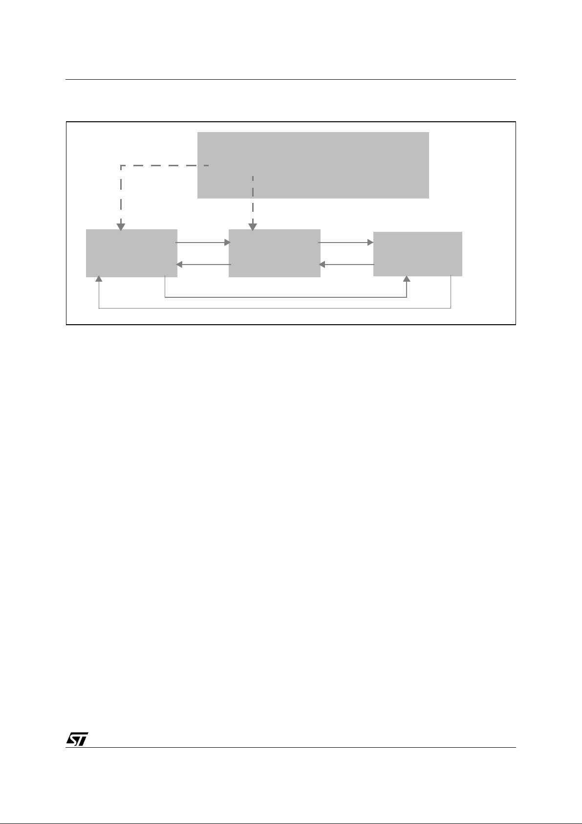
Figure 19. FIFO Transmission System
ST7 pCAN PERIPHERAL DRIVER
Next data to send
Object 1 Object 2
& message & message
FIFO Management
1st object
last object
Next
Preceding
in use?
current size = xx
Next
Object 3
& message
Preceding
Preceding
Next
For more informatio n, refer to Section 3.2.2 "Internal Routines", (CAN_In_Queue and
CAN_Out_Queue).
3.2.1.2 Software Filters
Once the
SOFTWARE_FILTERS
option is defined in can_custom.h and the list of filters is
completed, the compiler will define and initialize a structure containing the data.
typedef struct{
u8 array_size;
u16* filters_array;
}CAN_Filters_Array;
This structu re is compo sed of th e size of the array , autom atical ly calcul ated at comp ilation,
and of an array of 2-byte long numbers.
Consequently, the following constants are defined in the can.c file:
const u16 i_filters[]=INIT_FILTERS;
const CAN_Filters_Array CAN_filters={
Size_Of_Words_Array(i_filters),
i_filters
};
As we can see, they are immediately initialized. Size_Of_Words_Array is a macro and i_filters
is the array filled with your data.
You can access the i_filters array, declared as
extern const
in can.h.
3.2.1.3 Enum Types
They are used as return values for some internal routines.
43/100
Page 44

ST7 pCAN PERIPHERAL DRIVER
typedef enum {CAN_FILTER_MATCH,CAN_FILTER_NO_MATCH}CAN_Filter_Status;
Return values of the software filtering routine.
typedef enum {ITERR,ITRECEPT,ITTRANSMIT,ITSCIF}IT_Type;
Return values of the routine that determines which IT has to be processed first.
typedef enum
{CAN_CLEAN_FATAL,CAN_CLEAN_SUCCESS,CAN_CLEAN_FAILURE}CAN_Clean_Error;
Return values of the Cleaning function.
3.2.1.4 Status Counter
static u8 status_counter=0;
This is a variable used by the Sleep function to determine the state of the reception and transmission registers. It is updated the following way:
– +1, when a reception IT is taken into account
– -1, when a reception buffer is released
– +1, when a message is put into the transmission queue
– -1, when a message is sent (in the IT function)
When the CA N_S le ep fun ct ion is ca lled, a sim ple tes t of th is v ariab le lets the dr iver kno w if
there are still pending jobs and if the Sleep operation must be cancelled.
3.2.2 Internal Routines
3.2.2.1 Static CAN_Filter_Status CAN_Filter(u16 ident_code)
INPUT CAN message identifier
OUTPUT Error status
DESCRIPTION
COMMENTS
Tests matching of IDs of received messages and software filters.
Possible returned status: CAN_FILTER_MATCH and CAN_FILTER_NO_MATCH
Called by CAN_Receive
Compiled only if FILTERS_ENABLED is set.
Priority is given here to SPEED, that’s why the code may look strange.
Performs a classical dichotomy al gorithm and compares the value given as parameter with the
contents of the i_filters array
.
44/100
Page 45

3.2.2.2 static IT_Type CAN_Get_IT_Type(void)
INPUT -OUTPUT Generic type of the event that caused the IT
Tests matching of IDs of received messages and software filters.
If the DEBUG option is defined, checks the IT Error flags first. Otherwise checks the
DESCRIPTION
COMMENTS Called by CAN_Interrupt.
Reception ITs first.
Possible status returned: ITRECEPT for reception IT, ITTRANSMIT for transmission
IT and ITERR for error IT.
Figure 20. CAN_Get_IT_Type Flowchart
ST7 pCAN PERIPHERAL DRIVER
Begin (Case DEBUG)
Y
EPND=1
N
Y
SCIF=1
N
Y
RXIFi=1
N
Y
TXIF=1
Returns ITERR
Returns ITSCIF
Returns ITRECEPT
Returns ITTRANSMIT
Begin (Case no DEBUG)
if status_
change_notification
SCIF=1
RXIFi=1
TXIF=1
if not status_
change_notification
SCIF=1
45/100
Page 46

ST7 pCAN PERIPHERAL DRIVER
3.2.2.3 static CAN_Init_Error CAN_Init(Init_Data_Ptr data_ptr, CAN_Bool run_set,
CAN_Bool wkup_set)
INPUT Pointer to an Init_Data structure, Boolean, Boolean
OUTPUT Error status
CAN cell internal registers initialization.
Not executed if RUN bit set.
DESCRIPTION
COMMENTS Called by CAN_Switch_On, CAN_First_Init
The first Boolean determines if the RUN bit has to be set or not. The second Boolean
determines if the cell has to send a wake-up dominant bit.
Possible status returned: CAN_INIT_FAILURE and CAN_INIT_SUCCESS
Figure 21. CAN_Init Flowchart
Begin
RUN=1
N
Y
Returns CAN_INIT_FAILURE
Writes timing registers
Writes Interrupt Control register
Writes filters/m a sks
Writes Control Status Register
Returns CAN_INIT_SUCCESS
46/100
Page 47

ST7 pCAN PERIPHERAL DRIVER
3.2.2.4 static CAN_Transmit_Error CAN_In_Que ue (C AN_Message* msg_to_queue)
INPUT Pointer on a CAN message
OUTPUT Error code
Tests matching of IDs of received messages and software filters.
DESCRIPTION
COMMENTS
Possible return values: CAN_FIFO_FULL, CAN_TRANSMIT_SUCCESS and
CAN_TRANSMIT _FATAL.
Must not be interrupted
Called by CAN_Transmit_Request
Figure 22. CAN_In_Queue Flowchart
Begin
Locks queue
Queue in use
N
Y
Returns CAN_TRANSMIT_FATAL
Returns CAN_FIFO_FULL
Returns CAN_TRANSMIT_SUCCESS
Y
FIFO full
Unlocks queue
N
Updates FIFO parameters
Unlocks queue
47/100
Page 48

ST7 pCAN PERIPHERAL DRIVER
3.2.2.5 static CAN_Message* CAN_Out_Queue (void)
INPUT -OUTPUT Pointer to a CAN message
DESCRIPTION
COMMENTS
Returns a pointer to the first message in the transmission queue and updates the
queue parameters
Must not be interrupted
Called by CAN_Fill_Transmission_Buffer
The algorithm is exactly the same as for CAN_In_Queue().
3.2.2.6 static CAN_Clean_Error CAN_Clean (void)
INPUT -OUTPUT Error status
Cleans the reception and transmission buffers, and resets the transmission queue in
the first initialization state.
DESCRIPTION
COMMENTS
Only affects pointers
Possible return values: CAN_CLEAN_FAILURE, CAN_CLEAN_SUCCESS and
CAN_CLEAN_FATAL
Must be called only in Sleep mode (run bit reset)
Must not be interrupted
Called by CAN_Sleep and CAN_Switch_Off
Figure 23. CAN_Clean Flowchart
Begin
N
RUN=1
Y
Returns
CAN_CLEAN_FAILURE
Returns
CAN_CLEAN_FATAL
Returns
CAN_CLEAN_SUCCESS
N
Queue in use
Locks queue
Y
Reinitializes queue
Unlocks queue
Clears all pending jobs
Clears all pending ITs
48/100
Page 49

ST7 pCAN PERIPHERAL DRIVER
3.2.2.7 static CAN_Transmit_Error CAN_Fill_Transmission_Buffer( )
INPUT -OUTPUT Error status
Fills the hardware buffer for transmission.
DESCRIPTION
COMMENTS
Possible return values: CAN_TRANSMIT_BUFFER_FULL,
CAN_TRANSMIT_NO_MSG and CA N_TRANS M IT_SUCCE SS
ITs have to be disabled
Called by CAN_Transmit_Request
Calls CAN_Out_Queue
Figure 24. CAN_Fill_Transmissio n_Buffer Flowchart
Begin
N
Selects buffer 1
RDY= 1
Returns
CAN_TRANSMIT_BUFFER_FULL
Returns
CAN_TRANSMIT_NO_MSG
Returns
CAN_TRANSMIT_SUCCESS
Y
N
CAN_Out_Queue()
Message exists
i.e. not NULL
Y
Fill the hardware buffer
message.buffer_rw=CFALSE
49/100
Page 50

ST7 pCAN PERIPHERAL DRIVER
3.2.2.8 static CAN_Receive_Error CAN_Store_Rcvd_Msg(u8 num_buff_hard,
CAN_Recept_Buffer* dest_ptr)
INPUT
OUTPUT Error status
DESCRIPTION
COMMENTS
Number of the hardware buffer to release, pointer to the buffer where the data must
be saved
Fetches data received in a hardware buffer.
Possible return values: CAN_ILLEGAL_IDENTIFIER and
CAN_RECEIVE_SUCCESS
ITs have to be disabled.
This function is called by CAN_Reception, only in case of reception of data.
The priority was given to SPEED here, that‘s why the code may look strange.
Figure 25. CAN_Store_Rcvd_Msg Flowchar t
Begin
Returns
CAN_ILLEGAL_IDENTIFIER
Retrieves data length
N
Legal value
i.e. <9
Y
Saves data in
the software buffer
50/100
Returns
CAN_RECEIVE_SUCCESS
Releases the hardware
buffer, therefore clearing
the IT flag
Page 51

ST7 pCAN PERIPHERAL DRIVER
3.2.2.9 static CAN_Receive_Error CAN_Receive( u8 num_buff_hard)
INPUT ID of the buffer to void, pointer on the software buffer to fill.
OUTPUT Error status
DESCRIPTION
COMMENTS
Fetches data received in a hardware buffer and saves them in a software buffer supplied by the application
ITs have to be disabled
Calls CAN_Filter (if SOFTWARE_FILTER option is enabled)
Calls CAN_Request_Buffer
Possible return values: CAN_F IL TERING_FAILU RE,.CAN_RECEIVE_ REMO TE,
CAN_NO_BUFFER, CAN_RECEIVE_FATAL and CAN_RECEIVE_ SUCC ESS
.
Figure 26. CAN Receive Flowchart
Retrieves message identifier
CAN_Filter()
if SOFTWARE_FILTERS defined
Releases hardware buffer
Calls
CAN_FILTERING_FAILURE
Calls
CAN_Remote_Reception_Notification()
Returns
CAN_Receive_Remote
Returns
CAN_NO_BUFFER
Returns
CAN_RECEIVE_FATAL
FILTER_MATCH
N
Releases hardware buffer
Releases hardware buffer
Releases hardware buffer
Begin
Y
Remote frame?
CAN_Request_Buffer()
N
Y
N
Y
Calls
Buffer exists?
Y
Buffer already
accessed?
N
N
Buffer free?
Releases hardware buffer
Calls
CAN_Data_Reception_Notification()
Y
status=success
N
Y
CAN-Store_Received_Message
Returns
CAN_RECEIVE_SUCCESS
51/100
Page 52

ST7 pCAN PERIPHERAL DRIVER
3.2.2.10 Interrupt Routine
INPUT -OUTPUT -DESCRIPTION Interrupt processing function.
Calls CAN_Get_IT_Type
CAN_Reception_Notification
CAN_Transmission_Notification
CAN_Fill_Transmission_Buffer
CAN_Dominant_Bit_Reception_Notification
COMMENTS
May call (optional, see Section 2.1.5.4 "Can_custom.h File "):
CAN_Transmission_Error_Notification
CAN_Bus_Passive_Notification
CAN_Bus_Active_Notification
CAN_Bus_Off_Notification
CAN_Overrun_Notification
CAN_General_Reception_Error_Notification
Figure 27. Interrupt Routine Flowchart
Begin
Case: ITRECEPT
Get_IT_Type()
SWITCH:
N
Buffer 3
N
Buffer 2
Y
BREAKBREAK
filled
filled
Same processing
as buffer 3
Y
CAN_Receive
CAN_Reception_Status
if DEBUG defined
52/100
Page 53

continued
Case: ITTRANSMIT
ST7 pCAN PERIPHERAL DRIVER
Clears interrupt flag
CAN_Transmission_Notification()
CAN_Fill_Transmission_Buffer()
CAN_Transmission_Error_Not ification()
Case: ITSCIF
if STATUS_CHANGE_NOTIFICATION defined
or RUN_ON_STARTUP not defined
Clears interrupt flag
CAN_Get_Status()
Y
status = STANDBY
N
if STATUS_CHANGE_NOTIFICATION defined
if DEBUG defined
BREAK
CAN_Dominant_Bit_Reception_Notification ()
SWITCH:
Remove IT
authorisation
if GENERAL_RECEPTION_ERROR defined
CAN_General_Reception_Error
_Notification()
Case: CAN_BUS_PASSIVE
CAN_Bus_Passive_Notification()
Case: CAN_BUS_ACTIVE
CAN_Bus_Active_Notification()
Case: CAN_BUS_OFF
CAN_Bus_Off_No tification()
BREAK
53/100
Page 54

ST7 pCAN PERIPHERAL DRIVER
continued
if DEBUG defined
Case: ITERR
ORIF IT
N
TEIF IT
N
Y
CAN_Overrun_Notification()
Clears interrupt flag
Y
CAN_Transmission_Error_Notification()
Clears interrupt flag
BREAK
54/100
Page 55

3.3 A FEW WORDS ABOUT DRIVER PERFORMANCE
3.3.1 CPU Load
Let’s imagine the following situation:
– Bus rate: 100 kilobauds
– Bus load: 80%
ST7 pCAN PERIPHERAL DRIVER
– F
CPU
: 8 MHz
– 14 identifiers (typical value) have to be received.
Let’s measure the time spent inside the inter rupt function when a messa ge is received. The
applica tion p roce ssi ng ins ide t he no tific ation func tion s mus t be m inima l: the y on ly ret urn a
buffer to be filled.
We retrieve the following results:
– 8 bytes data message, filter match: 105 µs
– 0 bytes data message, filter match: 90 µs
– Any message, filter no match: 50 µs
Note: Any message, if only the eight most significant bits match, takes 100 µs. That is to say almost as
much time as with matching identifier. So it is better to chose the identifiers wisely, in order to prevent
this from occurring as much as possible.
The longest possible message (2.0A stan dard) is 130 bits long (including stuffing bits). Imagine that all messages on the bus are that long. Consequently, there will be 6 15 messages
per second on the bus , that’s to say one mes sage every 1.625 µs. The sav ing of data la sts
105 µs, so the C PU load is in this case 6.5%.
The same calculation for 0-byte messages (shortest possible) leads us to 15.3% CPU load.
Note that these are worst case scenarios! Not all the messages on the bus have to be saved.
And the bus load chosen here is pretty heavy (typical values are rather around 40%).
Do not forget to mu ltiply or di vide th ese va lues if y ou w ant a n esti mation of C PU load under
other bus speed/bus loading conditions and other F
CPU
speeds.
55/100
Page 56

ST7 pCAN PERIPHERAL DRIVER
3.3.2 Code Size
The numbers given here correspond to the size of the driver code WITHOUT any addition of
application specific code.
3.3.2.1 Can.o Module
Table 2. Can.o Code Size
ROM RAM (page 0) RAM (Default)
Functions 1326 bytes -- --
Variables
& Constants
10 bytes 19 bytes (shared segment) 28 bytes
3.3.2.2 Can_custom.o Module
Table 3. Can_custom.o Code Size
ROM RAM (page 0) RAM (Default)
Functions 5 bytes -- --
Variables
& Constants
-- -- --
56/100
Page 57

ST7 pCAN PERIPHERAL DRIVER
4 DRIVER CODE
4.1 CAN.C
/*********************** (c) 2000 STMicroelectronics *************************
PROJECT :
COMPILER : ST7 COSMIC C v4.2e
MODULE : can.c
VERSION : V 1.1.6 build 80
CREATION DATE : 04/00
AUTHOR : Central Europe 8bit Micro Application Group
-*-*-*-*-*-*-*-*-*-*-*-*-*-*-*--*-*-*-*-*-*-*-*-*-*-*-*-*-*-*-*-*-*-*-*-*-*-
DESCRIPTION : CAN routines
-*-*-*-*-*-*-*-*-*-*-*-*-*-*-*-*-*-*-*-*-*-*--*-*-*-*-*-*-*-*-*-*-*-*-*-*-*-
MODIFICATIONS : RIM statement removed from interrupt routine (1.0.0)
Transmission and reception structures merged into one "buffer
type"(1.1.1)
Management of semaphores (buffer_rw and
buffer_free)slightly modified(1.1.2)
Updated to comply with ST7ap_II (1.1.2 build 80)
IT management slightly modified (1.1.3)
Modif. transmission IT >> flag reset(1.1.4)
Bug corrected in CAN_Switch_Off(1.1.5)
Reset of ITs vector in CAN_Init(1.1.6)
****************************************************************************
THE SOFTWARE INCLUDED IN THIS FILE IS FOR GUIDANCE ONLY. ST MICROELECTRONICS
SHALL NOT BE HELD LIABLE FOR ANY DIRECT, INDIRECT OR CONSEQUENTIAL DAMAGES
WITH RESPECT TO ANY CLAIMS ARISING FROM USE OF THIS SOFTWARE.
***************************************************************************/
#include "lib.h"
#include "can.h"
#include "can_hr.h"
#include "can_custom.h"
57/100
Page 58

ST7 pCAN PERIPHERAL DRIVER
//Compilation options coherence check
#ifndef DEBUG
#ifdef GENERAL_RECEPTION_ERROR
#error "Debug not defined in CAN_custom.h"
#endif
#ifdef SIMULTANEOUS_EMISSION_RECEPTION
#error "Debug not defined in CAN_custom.h"
#endif
#endif
#ifdef GENERAL_RECEPTION_ERROR
#ifdef STATUS_CHANGE_NOTIFICATION
#error "GENERAL_RECEPTION_ERROR and
STATUS_CHANGE_NOTIFICATION incompatibles in CAN_custom.h"
#endif
#endif
/
*#########################################################################*/
/* CONSTANTS ALIAS */
/
*#########################################################################*/
#define PAGE_1 1 /* */
#define PAGE_2 2 /* CAN */
#define PAGE_3 3 /* pages */
#define PAGE_FILTERS 4 /* */
#define RECEPTION_2 2 /*Receptions buffers*/
#define RECEPTION_3 3
#define MAX_FIFO_SIZE 3 /*Size of the emission FIFO*/
#define RECEPT_MASK 0xC0 /*Masks */
#define TRANSMIT_MASK 0x10/*to retrieve specific*/
#define SCIF_MASK 0x08 /*IT flags */
#define ERROR_MASK 0x01
#define FILTER_SHIFT 1 /*Shift applied to the identifiers managed by software
58/100
Page 59

ST7 pCAN PERIPHERAL DRIVER
*/
// to give them the correct hardware format
#define REMOTE_BIT 5 /*Place of the remote bit in the ID field*/
#define REGISTER_SIZE 8 /*Size of a register*/
/
*#########################################################################*/
/* STRUCTURES TYPEDEF */
/
*#########################################################################*/
//Transmission queue element
typedef struct FIFO_Object{ // Definition of the reception FIFO unit
CAN_Buffer* message; // Pointer to a CAN message structure
struct FIFO_Object* next_object; // Pointer to the following object
in the queue
struct FIFO_Object* preceding_object; // Pointer on the
preceding object in the queue
}FIFO_Object; //
//Transmission queue
typedef struct { // Definition of the reception FIFO type
u8 fifo_size; // Size of the FIFO
FIFO_Object* first_object; // Next object to be outqueued
FIFO_Object* last_object; // Next place to fill
CAN_Bool isinuse; // Data sharing control
} FIFO;
#ifdef FILTERS_ENABLED
//Filtering results
typedef enum {CAN_FILTER_MATCH,CAN_FILTER_NO_MATCH}CAN_Filter_Status;
#endif
//IT types
typedef enum {ITERR,ITRECEPT,ITTRANSMIT,ITSCIF}IT_Type;
//Clean error codes
typedef enum
{CAN_CLEAN_FATAL,CAN_CLEAN_SUCCESS,CAN_CLEAN_FAILURE}CAN_Clean_Error;
/
*#########################################################################*/
/* VARIABLES */
59/100
Page 60

ST7 pCAN PERIPHERAL DRIVER
/
*#########################################################################*/
//Static variables
//Transmission queue
static FIFO CAN_transmit_queue;
static FIFO_Object CAN_queue_object_1;
static FIFO_Object CAN_queue_object_2;
static FIFO_Object CAN_queue_object_3;
volatile static u8 status_counter=0; //this counter is used by the sleep function to determine the state
//of the reception and emission registers
//It is used the following way :
//+1 when a reception IT is taken into account
//-1 when a received buffer is released
//+1 when a message is put into emission queue
//-1 when a message is sent (in the IT function)
//This is not a shared data, so no particular protection
/
*#########################################################################*/
/* CONSTANTES */
/
*#########################################################################*/
#ifdef FILTERS_ENABLED
const u16 i_filters[]=INIT_FILTERS; // Initialization of the filters
const u8 CAN_Filters_Array_Size=Size_Of_Words_Array(i_filters); // is defined
in can_hr.h
// Conditionnal compi-
lation : only if FILTERS_ENABLED
// the datas are then stored
into ROM
#endif
const Init_Data first_init_data={INIT_BRPR, //That structure is written by the
preprocessor
60/100
Page 61

ST7 pCAN PERIPHERAL DRIVER
INIT_BTR, //and stored into ROM. It can’t be
modified then.
INIT_FHR0,//But can be accessed (defined as ex-
ternal in can.h)
INIT_FLR0,
INIT_MHR0,
INIT_MLR0,
INIT_FHR1,
INIT_FLR1,
INIT_MHR1,
INIT_MLR1,
};
/
*#########################################################################*/
/* FUNCTIONS */
/
*#########################################################################*/
////////////////////////////////////////////////////////////////////////////
//Notification functions/////////////////////////////////////////////////////
////////////////////////////////////////////////////////////////////////////
CAN_Buffer* CAN_Request_Buffer(u16);
void CAN_Data_Reception_Notification(u16);
void CAN_Remote_Reception_Notification(u16);
void CAN_Transmission_Notification(void);
void CAN_Dominant_Bit_Reception_Notification(void);
#ifdef DEBUG
void CAN_Overrun_Notification(void);
void CAN_Transmission_Error_Notification(CAN_Transmit_Error);
void CAN_Reception_Status(CAN_Receive_Error);
#endif
#ifdef GENERAL_RECEPTION_ERROR
void CAN_General_Reception_Error_Notification(void);
#endif
#ifdef STATUS_CHANGE_NOTIFICATION
void CAN_Bus_Passive_Notification(void);
void CAN_Bus_Active_Notification(void);
61/100
Page 62

ST7 pCAN PERIPHERAL DRIVER
void CAN_Bus_Off_Notification(void);
#endif
//////////////////////////
//can.c static functions//
//////////////////////////
#ifdef FILTERS_ENABLED
/*-------------------------------------------------------------------------ROUTINE NAME : CAN_Filter
INPUT/OUTPUT : identifier code/error status
DESCRIPTION : Tests matching of IDs of received messages and software filters.
COMMENTS : Called by CAN_Recept
Compiled only if FILTERS_ENABLED is set.
Possible returned status : CAN_FILTER_MATCH
CAN_FILTER_NO_MATCH
--------------------------------------------------------------------------*/
static CAN_Filter_Status CAN_Filter(u16 ident_code)
{
u8 current_first;
u8 current_last;
u8 current_checked;
int current_content;
current_first = 0;
current_last = CAN_Filters_Array_Size - 1;
for (;;)
{
current_checked = (u8)(current_first + current_last) >> 1;
current_content = i_filters[current_checked] - ident_code;
if (current_content < 0)
{
current_first = current_checked + 1;
if (current_first > current_last)
break;
62/100
Page 63

ST7 pCAN PERIPHERAL DRIVER
}
else if (current_content == 0)
return (CAN_FILTER_MATCH);
else
{
current_last = current_checked - 1;
if (current_last < current_first)
break;
}
}
return (CAN_FILTER_NO_MATCH);
}
#endif /*ifdef FILTERS_ENABLED*/
/*-------------------------------------------------------------------------ROUTINE NAME : CAN_Get_IT_Type
INPUT/OUTPUT : -- / generic type of the event that caused the IT
DESCRIPTION : IT type fetching routine
COMMENTS : Called by CAN_Interrupt
Possible status returned : ITRECEPT for reception IT
ITTRANSMIT for transmission IT
ITERR for error IT
--------------------------------------------------------------------------*/
static IT_Type CAN_Get_IT_Type(void)
{
#ifdef DEBUG /*In this case, priority is given to error detection*/
if ((ERROR_MASK & CANISR)!=0)
{
return ITERR;
}
else if ((SCIF_MASK & CANISR)!=0)
{
return ITSCIF;
}
#endif
#ifdef SATUS_CHANGE_NOTIFICATION /*In this case, prioity given to status change,
eg. to early detect bus-off state*/
#ifndef DEBUG /*If debug is defined, this IT has already been
taken into account*/
63/100
Page 64

ST7 pCAN PERIPHERAL DRIVER
if ((SCIF_MASK & CANISR)!=0)
{
return ITSCIF;
}
#endif
#endif
if ((RECEPT_MASK & CANISR)!=0) //If not debug, priority is given to recept.,
then emission, then Status-Change/Wake-up condition//
{
return ITRECEPT;
}
else if ((TRANSMIT_MASK & CANISR)!=0) //If not, tests a transmit. IT
{
return ITTRANSMIT;
}
#ifndef DEBUG /*In this case, this IT hasn’t been tested yet*/
#ifndef SATUS_CHANGE_NOTIFICATION
else if ((SCIF_MASK & CANISR)!=0)
{
return ITSCIF;
}
#endif
#endif
}
/*-------------------------------------------------------------------------ROUTINE NAME : CAN_Init
INPUT/OUTPUT : Pointer on an init structure/Error status
DESCRIPTION : CAN cell internal registers initialization
COMMENTS : Called by CAN_Switch_On,CAN_First_Init
Not executed if RUN bit reset
Possible status returned : CAN_INIT_FAILURE
CAN_INIT_SUCCESS
--------------------------------------------------------------------------*/
CAN_Init_Error CAN_Init(Init_Data_Ptr data_ptr,CAN_Bool run_set,CAN_Bool
wkup_set)
{
if (!ValBit(CANCSR,RUN))
64/100
Page 65

ST7 pCAN PERIPHERAL DRIVER
{
/*Registers init*/
CANBRPR=data_ptr->brpr_init;//Init of timing variables
CANBTR=data_ptr->btr_init;
//Reset CANISR register
CANISR = 0x00;
//Calculation of the CANICR value
CANICR=0x30; //Default value : recept., transmit.
#ifdef STATUS_CHANGE_NOTIFICATION
CANICR=CANICR|0x08; //A bus wake up may not be wished, but a status change
monitoring is wanted
#endif
#ifdef DEBUG
CANICR=CANICR|0x06;
#endif
#ifdef GENERAL_RECEPTION_ERROR
CANICR=CANICR|0x40; //Sets the ESCI bit & the SCIF bit
#endif /*GENERAL_RECEPTION_ERROR*/
//Select filters/masks page
CANPSR=PAGE_FILTERS;
CANMLR0=data_ptr->mlr0_init;
CANMHR0=data_ptr->mhr0_init;
CANFLR0=data_ptr->flr0_init;
CANFHR0=data_ptr->fhr0_init;
CANMLR1=data_ptr->mlr1_init;
CANMHR1=data_ptr->mhr1_init;
CANFLR1=data_ptr->flr1_init;
CANFHR1=data_ptr->fhr1_init;
/*Calculation of the CANCSR register value*/
CANCSR=0x00;
if (wkup_set)
{
SetBit(CANCSR,WKPS);
}
#ifdef SIMULTANEOUS_EMISSION_RECEPTION
65/100
Page 66

ST7 pCAN PERIPHERAL DRIVER
SetBit(CANCSR,SRTE);
#endif /*SIMULTANEOUS_EMISSION_RECEPTION*/
if (run_set)
{
CAN_RUN_Cell();
}
return CAN_INIT_SUCCESS;
}
else {
return CAN_INIT_FAILURE;
}
}
/*-------------------------------------------------------------------------ROUTINE NAME : CAN_In_Queue
INPUT/OUTPUT : pointer on a CAN buffer
output error code
DESCRIPTION : Put a message given by the application into the transmission queue
Updates the queue parameters
COMMENTS : Called by CAN_Transmit_Request
Must not be interrupted
Possible return values : CAN_FIFO_FULL
CAN_TRANSMIT_SUCCESS
CAN_TRANSMIT_FATAL
--------------------------------------------------------------------------*/
static CAN_Transmit_Error CAN_In_Queue (CAN_Buffer* msg_to_queue)
{
if (CAN_transmit_queue.isinuse) //Necessary to avoid multiple simultaneous
access
{
return CAN_TRANSMIT_FATAL; //Time out ?
} //to the datas
CAN_transmit_queue.isinuse=CTRUE; //Locks the queue
if ((CAN_transmit_queue.fifo_size)>=MAX_FIFO_SIZE) //Tests if the FIFO is
already full
{
CAN_transmit_queue.isinuse=CFALSE; //If yes, releases the queue
return CAN_FIFO_FULL; //...and aborts process
66/100
Page 67

ST7 pCAN PERIPHERAL DRIVER
}
else
{
//If not, goes on processing
CAN_transmit_queue.last_object=(CAN_transmit_queue.last_object-
>next_object);
CAN_transmit_queue.last_object->message=msg_to_queue;
CAN_transmit_queue.fifo_size=(CAN_transmit_queue.fifo_size)+1;
CAN_transmit_queue.isinuse=CFALSE;
return CAN_TRANSMIT_SUCCESS; //Releases the queue
}
}
/*-------------------------------------------------------------------------ROUTINE NAME : CAN_Out_Queue
INPUT/OUTPUT : -- /pointer on a CAN buffer
DESCRIPTION : Returns a pointer on the first message in the transmission queue.
Update the queue parameters
COMMENTS : Called by CAN_TransmitRequest
Must not be interrupted
--------------------------------------------------------------------------*/
static CAN_Buffer* CAN_Out_Queue (void)
{
CAN_Buffer* result;
if (CAN_transmit_queue.isinuse) //Necessary to avoid multiple simultaneous
access
{ //to the datas
return CAN_TRANSMIT_FATAL; //CAN_TRANSMIT_FATAL=0, that’s why the compiler
authorises such a return value (<=>NULL)
}
CAN_transmit_queue.isinuse=CTRUE; //Locks the queue
if ((CAN_transmit_queue.fifo_size)==0) //If the queue is empty
{
CAN_transmit_queue.isinuse=CFALSE; //Releases it
return NULL;
}
else
{ //Else goes on processing
67/100
Page 68

ST7 pCAN PERIPHERAL DRIVER
result=CAN_transmit_queue.first_object->message;
CAN_transmit_queue.first_object->message=NULL; //Updates queue
parameters
CAN_transmit_queue.first_object=CAN_transmit_queue.first_object-
>next_object;
CAN_transmit_queue.fifo_size=(CAN_transmit_queue.fifo_size)-1;
CAN_transmit_queue.isinuse=CFALSE; //Releases the queue
return result;
}
}
/*-------------------------------------------------------------------------ROUTINE NAME : CAN_Clean
INPUT/OUTPUT : -- /error status
DESCRIPTION : Cleans the recept. and emission buffers, and resets the transmission queue.
COMMENTS : Must be called only in sleep mode (run bit reset)
Must not be interrupted
Only affects pointers
Called by CAN_Sleep and CAN_Kill
Possible return values : CAN_CLEAN_FAILURE
CAN_CLEAN_SUCCESS
CAN_CLEAN_FATAL
--------------------------------------------------------------------------*/
static CAN_Clean_Error CAN_Clean (void)
{
if (!ValBit(CANCSR,RUN)) //No cleaning while the CAN node is running
{
//Cleaning transmission queue
if (CAN_transmit_queue.isinuse)
{
return CAN_CLEAN_FATAL;
}
CAN_transmit_queue.isinuse=CTRUE; //Locks the queue
CAN_transmit_queue.first_object=&CAN_queue_object_1; //Reinit. the
queue
CAN_transmit_queue.last_object=&CAN_queue_object_3; //(In the same
68/100
Page 69

state than after 1st. init
CAN_transmit_queue.fifo_size=0;
CAN_queue_object_1.message=NULL;
CAN_queue_object_2.message=NULL;
CAN_queue_object_3.message=NULL;
CAN_transmit_queue.isinuse=CFALSE;//Releases the queue
//Hardware cleaning (releases the hardware buffers)
CANPSR=PAGE_3;
while (CANPSR>0)
{
Clr_RDY_Bit();
CANPSR--;
}
//IT cleaning : clears any pending IT flag
CANISR=CANISR&0;
return CAN_CLEAN_SUCCESS;
ST7 pCAN PERIPHERAL DRIVER
}
else
{
return CAN_CLEAN_FAILURE;
}
}
/*-------------------------------------------------------------------------ROUTINE NAME : CAN_Fill_Transmission_Buffer
INPUT/OUTPUT : -- / error status
DESCRIPTION : Fills the hadrware buffer for transmission.
COMMENTS : ITs have to be disabled
Called by CAN_Transmit_Request
Calls CAN_Out_Queue
Possible return values : CAN_TRANSMIT_BUFFER_FULL
CAN_TRANSMIT_NO_MSG
CAN_TRANSMIT_SUCCESS
--------------------------------------------------------------------------*/
CAN_Transmit_Error CAN_Fill_Transmission_Buffer(void)
{
CANPSR=PAGE_1;
69/100
Page 70

ST7 pCAN PERIPHERAL DRIVER
if (ValBit(CANBCSR,RDY)) //Check if the register is already in use
{
return CAN_TRANSMIT_BUFFER_FULL; //Exit if yes
}
else
{
CAN_Buffer* msg_to_send_ptr;
u8* data_ptr;
CAN_Data_Size data_length;
msg_to_send_ptr=CAN_Out_Queue(); //If no, get the first message
in the queue
if (msg_to_send_ptr==NULL)
{
return CAN_TRANSMIT_NO_MSG; //Aborts process if queue
empty
}
CANIDLR=0x00;
CANIDHR=0x00;
data_length=msg_to_send_ptr->data_size;
data_ptr=msg_to_send_ptr->CAN_msg_data;
//!!!Code is here dependant of the order of the fields in the data structure
//Writing both CANIDHR and CANIDLR
CANIDLR = *(((unsigned char*)msg_to_send_ptr)+1);
CANIDHR = *((unsigned char*)msg_to_send_ptr);
_asm("SLL _CANIDLR \n RLC _CANIDHR");
{
register u8 counter;
if (data_length==REMOTE_FRAME) /*If remote frame, send immediately*/
{
SetBit(CANIDLR,RTR);
}
else
{
CANIDLR |= data_length;
for (counter=0;counter<data_length;counter++)
{
70/100
Page 71

ST7 pCAN PERIPHERAL DRIVER
CANDR[counter]=data_ptr[counter];
}
}
counter=7;
CANDR[7]=data_ptr[counter];
}
msg_to_send_ptr->buffer_free=CTRUE;
msg_to_send_ptr->buffer_rw=CFALSE;
}
return CAN_TRANSMIT_SUCCESS;
}
/*-------------------------------------------------------------------------ROUTINE NAME : CAN_Store_Rcvd_Msg
INPUT/OUTPUT : ID of the buffer to void/Status message
DESCRIPTION : Fetches the datas received in a hardware buffer.
COMMENTS : ITs have to be disabled
This fuction is called by CAN_Recept, only in case of reception of datas
Priority given to SPEED here, that‘s why the code may look strange
Possible return values : CAN_ILLEGAL_IDENTIFIER
CAN_RECEIVE_SUCCESS
--------------------------------------------------------------------------*/
static CAN_Receive_Error CAN_Store_Rcvd_Msg(CAN_Buffer* dest_ptr)
{
u8* data_ptr;
u8 data_size;
//CANPSR=num_buff_hard;
data_ptr=(dest_ptr->CAN_msg_data);
data_size=(CANIDLR&0x0F);
if(data_size>8)
{
Clr_RDY_Bit();
return CAN_ILLEGAL_IDENTIFIER;
}
dest_ptr->data_size=data_size;//Saving data size
{
register u8 counter;
71/100
Page 72

ST7 pCAN PERIPHERAL DRIVER
for (counter=0;counter<data_size;counter++)
{
data_ptr[counter]=CANDR[counter];
}
}
Clr_RDY_Bit(); //Releases the buffer and clears the IT flag
return CAN_RECEIVE_SUCCESS;
}
/*-------------------------------------------------------------------------ROUTINE NAME : CAN_Receive
INPUT/OUTPUT : ID of the buffer to void/Status message
DESCRIPTION : Fetches the datas received in a hardware buffer and saves them in a
soft buffer
furnished by the application.
COMMENTS : ITs have to be disabled
Calls CAN_Filter (optionnal)
CAN_Request_Buffer
CAN_Store_Rcvd_Msg
Possible return values : CAN_FILTERING_FAILURE
CAN_NO_BUFFER
CAN__RECEIVE_FATAL
CAN_RECEIVE_SUCCESS
--------------------------------------------------------------------------*/
static CAN_Receive_Error CAN_Receive(u8 num_buff_hard)
{
CAN_Buffer* soft_buffer_ptr;
CAN_Receive_Error receive_status;
u16 message_ident;
#ifdef FILTERS_ENABLED /*Conditionnal compilation*/
CAN_Filter_Status filtering_status;
#endif
//Retrieving the ID of the message
CANPSR=num_buff_hard;
72/100
Page 73

ST7 pCAN PERIPHERAL DRIVER
message_ident = (((unsigned int)CANIDHR)<<8)|CANIDLR;
message_ident >>= FILTER_SHIFT; //Appropriate rigth shift
message_ident &= 0xFFF0;
//Filtering function
#ifdef FILTERS_ENABLED /*Conditionnal compilation*/
filtering_status=CAN_Filter(message_ident); //Filtering fonction call
if (filtering_status==CAN_FILTER_NO_MATCH)
{
Clr_RDY_Bit(); //Frees the hardware buffer for a
new reception
return CAN_FILTERING_FAILURE;
}
#endif
//Tests if remote frame
if(ValBit(CANIDLR,4))
{
Clr_RDY_Bit();
CAN_Remote_Reception_Notification(message_ident);
return CAN_RECEIVE_REMOTE;
}
//Else, saves the datas in a buffer passed by the application
soft_buffer_ptr=CAN_Request_Buffer(message_ident); //Requests a buffer for
the messsage that successfully passed the filters
if (soft_buffer_ptr==NULL) //The buffer must exist prior to beeing filled
!!!
{
Clr_RDY_Bit();
return CAN_NO_BUFFER; //Kind of "software overrun"
}
if (soft_buffer_ptr->buffer_rw)
{
Clr_RDY_Bit();
return CAN_RECEIVE_FATAL;
}
soft_buffer_ptr->buffer_rw=CTRUE;//Locks the buffer
if (!(soft_buffer_ptr->buffer_free))
{
73/100
Page 74

ST7 pCAN PERIPHERAL DRIVER
Clr_RDY_Bit();
soft_buffer_ptr->buffer_rw=CFALSE;//If the buffer is full, releases it
return CAN_RECEIVE_FATAL; //and exit
}
receive_status=CAN_Store_Rcvd_Msg(soft_buffer_ptr); //Saves message and releases the hardware buffer
//Writing identifier :
*(int*)soft_buffer_ptr = message_ident;
//End of routine :
if (receive_status!=CAN_RECEIVE_SUCCESS)
{
Clr_RDY_Bit();
soft_buffer_ptr->buffer_rw=CFALSE;//In case of failure, releases the
buffer and exits
return CAN_RECEIVE_FATAL;
}
soft_buffer_ptr->buffer_free=CFALSE; //In case of success, marks the buffer
as in use
soft_buffer_ptr->buffer_rw=CFALSE; //Unlock it
CAN_Data_Reception_Notification(message_ident);
return CAN_RECEIVE_SUCCESS;
}
/*-------------------------------------------------------------------------ROUTINE NAME : CAN_Interrupt
INPUT/OUTPUT : -- /--
DESCRIPTION : interrupt processing function
COMMENTS : Each case must be taken into account.
Calls CAN_Get_IT_Type
CAN_Reception_Notification
CAN_Transmission_Notification
CAN_Fill_Transmission_Buffer
CAN_Dominant_Bit_Reception_Notification
May call (optionnal) :
CAN_Transmission_Error_Notification
CAN_Bus_Passive_Notification
CAN_Bus_Active_Notification
CAN_Bus_Off_Notification
74/100
Page 75

ST7 pCAN PERIPHERAL DRIVER
CAN_Overrun_Notification
CAN_General_Reception_Error_Notification
--------------------------------------------------------------------------*/
@interrupt @nostack void CAN_Interrupt(void)
{
IT_Type it_type;
it_type=CAN_Get_IT_Type();
switch(it_type)
{
case ITRECEPT :
{
CAN_Receive_Error error_status;
if (ValBit(CANISR,RXIF3)) //Check the lower priority buffer
first
{
status_counter=status_counter+1;
error_status=CAN_Receive(RECEPTION_3);
#ifdef DEBUG
CAN_Reception_Status(error_status);
#endif
status_counter=status_counter-1;
}
if(ValBit(CANISR,RXIF2)) //Then checks the other
{
status_counter=status_counter+1;
error_status=CAN_Receive(RECEPTION_2);
#ifdef DEBUG
CAN_Reception_Status(error_status);
#endif
status_counter=status_counter-1;
}
break;
}
case ITTRANSMIT : //Transmission IT
{
CAN_Transmit_Error status;
status counter
Clr_TXIF_Bit();//Clearing the flag
status_counter=status_counter-1; //Decrementing the
75/100
Page 76

ST7 pCAN PERIPHERAL DRIVER
CAN_Transmission_Notification();
status=CAN_IT_Fill_Transmission_Buffer();
#ifdef DEBUG
if (status!=CAN_TRANSMIT_SUCCESS)
{
CAN_Transmission_Error_Notification(status); //
When an unsuccesfull transmission occured (argument : error status?)
}
#endif
break;
}
case ITSCIF :
{
CAN_Status status;
Clr_SCIF_Bit();
status=CAN_Get_Status();
if (status==CAN_STANDBY)
{
CAN_Dominant_Bit_Reception_Notification(); //Re-
ception of a dominant bit while in stanby mode
#ifndef STATUS_CHANGE_NOTIFICATION
ClrBit(CANICR,SCIE); //After first init, this IT is
no more needed if
#endif /
*STATUS_CHANGE_NOTIFICATION is not requested*/
}
#ifdef STATUS_CHANGE_NOTIFICATION
switch (status)
{
case CAN_BUS_PASSIVE :
CAN_Bus_Passive_Notification(); //Status change to
bus passive
break;
case CAN_BUS_ACTIVE :
CAN_Bus_Active_Notification(); //Status change to
bus active
break;
case CAN_BUS_OFF :
CAN_Bus_Off_Notification(); //Response to a status
change to bus-off
break;
default :
/////////////////////////
76/100
Page 77

ST7 pCAN PERIPHERAL DRIVER
//Default case///////////
//Should never happen////
//Write debug code here//
/////////////////////////
break;
}
#endif
#ifdef GENERAL_RECEPTION_ERROR
{
CAN_General_Reception_Error_Notification();
Clr_SCIF_Bit();
}
#endif
break;
}
#ifdef DEBUG
case ITERR :
{
if (ValBit(CANISR,ORIF))
{
CAN_Overrun_Notification();
Clr_ORIF_Bit();
}
else if (ValBit(CANISR,TEIF))
{
CAN_Transmission_Error_Notification(CAN_TRANSMISSION_ERROR_IT);
Clr_TEIF_Bit();
}
break;
}
#endif
default :
//////////////////////////////////////////
//Default case (should never be reached)//
//Debug code//////////////////////////////
//////////////////////////////////////////
break;
}
}
/* PUBLIC FUNCTIONS
77/100
Page 78

ST7 pCAN PERIPHERAL DRIVER
**********************************************************/
/* List of all functions defined in this module and used in other modules */
/*-------------------------------------------------------------------------ROUTINE NAME : CAN_Get_TEC()
INPUT/OUTPUT : -/Value of the TECR register (transmission error counter)
DESCRIPTION : Returns the value of the TECR register
COMMENTS :
--------------------------------------------------------------------------*/
u8 CAN_Get_TEC(void)
{
return CANTECR;
}
/*-------------------------------------------------------------------------ROUTINE NAME : CAN_Get_REC()
INPUT/OUTPUT : -/Value of the RECR register (reception error counter)
DESCRIPTION : Returns the value of the TECR register
COMMENTS :
--------------------------------------------------------------------------*/
u8 CAN_Get_REC(void)
{
return CANRECR;
}
/*-------------------------------------------------------------------------ROUTINE NAME : CAN_Get_Status
INPUT/OUTPUT : -- / current status of the cell
DESCRIPTION : Retrieves the current status of the CAN cell.
COMMENTS : Possible return values : CAN_STANDBY
CAN_BUS_PASSIVE
CAN_BUS_OFF
CAN_BUS_ACTIVE
--------------------------------------------------------------------------*/
CAN_Status CAN_Get_Status (void)
78/100
Page 79

ST7 pCAN PERIPHERAL DRIVER
{
if (!ValBit(CANCSR,RUN))
{
return CAN_STANDBY;
}
else
{
if (ValBit(CANCSR,EPSV))
{
return CAN_BUS_PASSIVE;
}
else
{
if (ValBit(CANCSR,BOFF))
{
return CAN_BUS_OFF;
}
else return CAN_BUS_ACTIVE;
}
}
}
/*-------------------------------------------------------------------------ROUTINE NAME : CAN_First_Init
INPUT/OUTPUT : --/ error status
DESCRIPTION : Can Cell power on initialisation Routine.
COMMENTS : Calls CAN_Init
Possible return value : CAN_INIT_FAILURE
CAN_INIT_SUCCESS
--------------------------------------------------------------------------*/
CAN_Init_Error CAN_First_Init(void)
{
if (!ValBit(CANCSR,RUN)) //The CAN node is not running and there is an init
structure
{
CAN_Bool run_set,wkps_set;
/*Transmition queue init*/
79/100
Page 80

ST7 pCAN PERIPHERAL DRIVER
CAN_queue_object_1.next_object=&CAN_queue_object_2; //The
transmission objects are being linked
CAN_queue_object_1.preceding_object=&CAN_queue_object_3;
CAN_queue_object_1.message=NULL;
CAN_queue_object_2.next_object=&CAN_queue_object_3;
CAN_queue_object_2.preceding_object=&CAN_queue_object_1;
CAN_queue_object_2.message=NULL;
CAN_queue_object_3.next_object=&CAN_queue_object_1;
CAN_queue_object_3.preceding_object=&CAN_queue_object_2;
CAN_queue_object_3.message=NULL;
CAN_transmit_queue.fifo_size=0;
CAN_transmit_queue.first_object=&CAN_queue_object_1;
CAN_transmit_queue.last_object=&CAN_queue_object_3; //Has to be initialized that way, or the first input will fail
CAN_transmit_queue.isinuse=CFALSE; //Releases queue
CANPSR=PAGE_1;
Clr_LOCK_Bit(); //Cancels any pending transmission
SetBit(CANBCSR,LOCK); //Thus the buffer 2 cannot be used for
reception
//Init of the hardware buffers
run_set=CFALSE;
#ifdef RUN_ON_START_UP
run_set=CTRUE;
#endif
wkps_set=CFALSE;
#ifdef WAKE_UP_PULSE
wkps_set=CTRUE;
#endif
status_counter=0;
#ifndef RUN_ON_START_UP
CANICR=CANICR|0x08; //ie. a bus wake-up is wished
#endif
if(CAN_1_Init(&first_init_data,run_set,wkps_set)==CAN_INIT_FAILURE)
80/100
Page 81

ST7 pCAN PERIPHERAL DRIVER
{
return CAN_INIT_FAILURE;
}
return CAN_INIT_SUCCESS;
}
else return CAN_INIT_FAILURE;
}
/*-------------------------------------------------------------------------ROUTINE NAME : CAN_It_Dis
INPUT/OUTPUT : --/--
DESCRIPTION : Reset of the CANICR register.
COMMENTS :
--------------------------------------------------------------------------*/
void CAN_It_Dis (void)
{
CANICR=0x00;
}
/*-------------------------------------------------------------------------ROUTINE NAME : CAN_Switch_Off
INPUT/OUTPUT : way the chip can be waken up : BUS_WAKEUP or SOFT_WAKEUP/error
status
DESCRIPTION : Puts the CAN node into standby state. Aborts any pending transmission
and doesn’t wait for the reception buffer to having been read.
A time out mechanism is implemented here (about 30ms). So if
you use the
watchdog in your application, REFRESH IT BEFORE CALLING THE
FUCNTION !
COMMENTS : Calls CAN_Clean
Possible return value : CAN_SLEEP_SUCCESS
CAN_SLEEP_FATAL
--------------------------------------------------------------------------*/
CAN_Switch_Error CAN_Switch_Off(WakeUp_Cause wucause)
81/100
Page 82

ST7 pCAN PERIPHERAL DRIVER
{
CAN_Clean_Error clean_status;
CAN_It_Dis(); //Resets the CANICR register
ClrBit(CANCSR,RUN);
while (ValBit(CANCSR,RUN))
{
static u16 counter=0xFFF; //Implement here a time out (171990 CPU cycles,
~21,4ms with 8MHz fcpu)
counter=counter-1;
if (counter==0)
{
return CAN_SLEEP_FATAL;
}
}
clean_status=CAN_Clean();
if (clean_status==CAN_CLEAN_FAILURE)
{
return CAN_SLEEP_FATAL;
}
if (wucause==BUS_WAKEUP) //We are then in the case when the uC has to be
waken up by the bus
{
Clr_SCIF_Bit(); //clears the CANISR TXIF flag, before reenabling ITs
SetBit(CANICR,SCIE); //sets the CANICR TXIE flag, before reenabling ITs
}
else if(wucause==SOFT_WAKEUP)
{
Clr_SCIF_Bit(); //clears the CANISR TXIF flag, before reenabling ITs
}
status_counter=0;
return CAN_SLEEP_SUCCESS;
}
/*-------------------------------------------------------------------------ROUTINE NAME : CAN_Sleep
INPUT/OUTPUT : way the chip can be waken up : BUS_WAKEUP or SOFT_WAKEUP/Error
status
82/100
Page 83

ST7 pCAN PERIPHERAL DRIVER
DESCRIPTION : Puts the CAN node into passive state. Returns an error if any
transmission request is pendingor if a hardware reception
buffer
is still unsaved. Dedicated to bus wake-up (for power save).
COMMENTS : Doesn’t call CAN_Clean.
Possible return values : CAN_SLEEP_ERROR
CAN_SLEEP_FATAL
CAN_SLEEP_SUCCESS
--------------------------------------------------------------------------*/
CAN_Switch_Error CAN_Sleep (WakeUp_Cause wucause)
{
if (status_counter==0)
{
CANPSR=PAGE_2;
SetBit(CANBCSR,LOCK);
if (!ValBit(CANBCSR,LOCK))
{
return CAN_SLEEP_ERROR;
}
CANPSR=PAGE_3;
SetBit(CANBCSR,LOCK);
if (!ValBit(CANBCSR,LOCK))
{
CANPSR=PAGE_2;
Clr_LOCK_Bit();
return CAN_SLEEP_ERROR;
}
//Then the CAN cell can be shut down
ClrBit(CANCSR,RUN);
if (ValBit(CANCSR,RUN)) //Be careful there !!!!!
{
return CAN_SLEEP_FATAL;
}
CANPSR=PAGE_2;
Clr_LOCK_Bit();
CANPSR=PAGE_3;
Clr_LOCK_Bit();
if (wucause==BUS_WAKEUP) //We are then in the case when the uC has to
be waken up by the bus
83/100
Page 84

ST7 pCAN PERIPHERAL DRIVER
{
Clr_SCIF_Bit(); //clears the CANISR TXIF flag, before
reenabling ITs
SetBit(CANICR,SCIE); /*sets the CANICR TXIE flag, before
reenabling ITs*/
}
else if(wucause==SOFT_WAKEUP)
{
Clr_SCIF_Bit(); //clears the CANISR TXIF flag, before
reenabling ITs
}
return CAN_SLEEP_SUCCESS;
}
return CAN_SLEEP_ERROR; //default exit
}
/*-------------------------------------------------------------------------ROUTINE NAME : CAN_Switch_on
INPUT/OUTPUT : pointer on an init data, order : emission of a dominant pulse by
wake up or not/error status
DESCRIPTION : Puts the CAN node into active state
COMMENTS : Calls CAN_Init
Possible return value : SWITCH_ON_SUCCES
SWITCH_ON_FAILURE
--------------------------------------------------------------------------*/
CAN_Switch_Error CAN_Switch_On (Init_Data_Ptr idptr, CAN_Bool wupulse_allowed)
{
if (!ValBit(CANCSR,RUN)) //The can must not be running
{
CAN_Switch_Error error_status;
status_counter=0;
CANPSR=PAGE_1;
Clr_LOCK_Bit(); //Cancels any pending transmission
SetBit(CANBCSR,LOCK); //Thus the buffer 1 cannot be used for reception
84/100
Page 85

ST7 pCAN PERIPHERAL DRIVER
if (idptr!=NULL) //If NULL, nothing will be reinitialized
{
error_status=CAN_Init(idptr,CTRUE,wupulse_allowed); //RUN set automat-
ically
if (error_status==CAN_INIT_FAILURE)
{
return CAN_SWITCH_ON_FAILURE;
}
}
return CAN_SWITCH_ON_SUCCES;
}
else return CAN_SWITCH_ON_FAILURE;
}
/*-------------------------------------------------------------------------ROUTINE NAME : CAN_Transmit_request
INPUT/OUTPUT : pointer on the CAN buffer to send/error status
DESCRIPTION : Puts a message into the queue, and may request an immediate
transmission if it’s void
COMMENTS : Calls CAN_Init_Queue and CAN_Fill_Transmission_Buffer
!!!This function MUST NOT be interrupted, so protect it with SIM and RIM
statements
when used OUTSIDE the notification fuctions of CAN_custom.c!!!
--------------------------------------------------------------------------*/
CAN_Transmit_Error CAN_Transmit_Request(CAN_Buffer* msg_to_send_ptr)
{
CAN_Transmit_Error status;
if (msg_to_send_ptr->buffer_rw==CTRUE)
{
return CAN_TRANSMIT_FAILURE;
}
msg_to_send_ptr->buffer_rw=CTRUE;
if (!ValBit(CANCSR,RUN)) //No transmission autorized when the CAN cell is
not running
{
85/100
Page 86

ST7 pCAN PERIPHERAL DRIVER
msg_to_send_ptr->buffer_rw=CFALSE;
return CAN_TRANSMIT_FAILURE;
}
status=CAN_In_Queue(msg_to_send_ptr); //Puts the message in the queue
if (status==CAN_FIFO_FULL)
{
msg_to_send_ptr->buffer_rw=CFALSE;
return status;
}
status_counter=status_counter+1;
status=CAN_Fill_Transmission_Buffer(); //Tries to fill the buffer 2
if (status==CAN_TRANSMIT_NO_MSG) //This should never happen
{
status_counter=status_counter-1;
msg_to_send_ptr->buffer_rw=CFALSE;
return CAN_TRANSMIT_FATAL;
}
else
{
return status; //Can be success or buffer in use (ie. a request
is already pending)
} //The modif of buffer_rw will be
executed by CAN_Store_Received_Message
}
/****** (c) 2000 STMicroelectronics ********************* END OF FILE _******/
4.2 CAN.H
/*********************** (c) 2000 STMicroelectronics *************************
PROJECT :
COMPILER : ST7 COSMIC C v4.2e
MODULE : can.h
VERSION : V 1.1.6 build 80
CREATION DATE : 04/00
86/100
Page 87

ST7 pCAN PERIPHERAL DRIVER
AUTHOR : Central Europe 8bit Micro Application Group
-*-*-*-*-*-*-*-*-*-*-*-*-**-*-*-*-*-*-*-*-*-*-*-*-*-*-*-*-*-*-*-*-*-*-*-*-*-
DESCRIPTION : CAN routines
-*-*-*-*-*-*-*-*-*-*-*-*--*-*-*-*-*-*-*-*-*-*-*-*-*-*-*-*-*-*-*-*-*-*-*-*-*-
MODIFICATIONS : none
***************************************************************************
THE SOFTWARE INCLUDED IN THIS FILE IS FOR GUIDANCE ONLY. ST MICROELECTRONICS
SHALL NOT BE HELD LIABLE FOR ANY DIRECT, INDIRECT OR CONSEQUENTIAL DAMAGES
WITH RESPECT TO ANY CLAIMS ARISING FROM USE OF THIS SOFTWARE.
***************************************************************************/
#ifndef CAN_H
#define CAN_H
#define CAN_MAX_DATA_SIZE 8
#ifndef _H_STDDEF_
#define NULL (void*) 0 /*Not already defined if stddef.h not included*/
#endif
#define NULL_DEFINED
/
*###########################################################################
*/
/* TYPEDEF */
/
*###########################################################################
*/
/////////////////////
//Simple data types//
/////////////////////
typedef enum {BUS_WAKEUP,SOFT_WAKEUP}WakeUp_Cause;
typedef enum
{DLC0,DLC1,DLC2,DLC3,DLC4,DLC5,DLC6,DLC7,DLC8,REMOTE_FRAME}CAN_Data_Size;
87/100
Page 88

ST7 pCAN PERIPHERAL DRIVER
//Error status messages
//Initialisation
typedef enum {CAN_INIT_SUCCESS,CAN_INIT_FAILURE}CAN_Init_Error;
//Sleep
typedef enum
{CAN_SLEEP_FATAL,CAN_SLEEP_ERROR,CAN_SLEEP_SUCCESS,CAN_SWITCH_ON_SUCCES,CAN_
SWITCH_ON_FAILURE}CAN_Switch_Error;
//Status
typedef enum
{CAN_RUN,CAN_STANDBY,CAN_BUS_ACTIVE,CAN_BUS_PASSIVE,CAN_BUS_OFF}CAN_Status;
//Misc.
typedef enum {CFALSE=0,CTRUE=1}CAN_Bool;
//Transmission-Reception
typedef enum
{CAN_TRANSMIT_FATAL,CAN_TRANSMIT_SUCCESS,CAN_TRANSMIT_FAILURE,CAN_TRANSMIT_N
O_MSG,CAN_FIFO_FULL,CAN_TRANSMIT_BUFFER_FULL,CAN_TRANSMISSION_ERROR_IT}CAN_T
ransmit_Error;
typedef enum
{CAN_RECEIVE_FATAL,CAN_RECEIVE_SUCCESS,CAN_RECEIVE_REMOTE,CAN_ILLEGAL_IDENTI
FIER,CAN_FILTERING_FAILURE,CAN_BUFFER_IN_USE,CAN_NO_BUFFER,CAN_RCV_BUFFER_NO
T_READY}CAN_Receive_Error;
//////////////////////////////////////
//Transmission/Reception structures //
//////////////////////////////////////
//Input/output structure
typedef struct CAN_Buffer{
u16 msg_identifier;
CAN_Data_Size data_size;
u8 CAN_msg_data[CAN_MAX_DATA_SIZE];
CAN_Bool buffer_rw;
CAN_Bool buffer_free; //shared variable
}CAN_Buffer;
/////////////////////////////
//Initialization parameters//
/////////////////////////////
//Initialisation data structure
typedef struct {
u8 brpr_init;
u8 btr_init;
u8 fhr1_init;
88/100
Page 89

ST7 pCAN PERIPHERAL DRIVER
u8 flr1_init;
u8 mhr1_init;
u8 mlr1_init;
u8 fhr0_init;
u8 flr0_init;
u8 mhr0_init;
u8 mlr0_init;
}Init_Data;
typedef Init_Data* Init_Data_Ptr; // Pointer on an Init_Data structure
/
*#########################################################################*/
/* VARIABLES */
/
*#########################################################################*/
//Initialization of the CAN-cell
//Variables declared in can.c
extern const Init_Data first_init_data; //Initialisation datas used at power-on
extern const u16 i_filters[]; // Array of accepted filters
/
*#########################################################################*/
/* FUNCTIONS */
/
*#########################################################################*/
//Power-on initialisation
CAN_Init_Error CAN_First_Init(void);
//Resets IT authorization flags
void CAN_It_Dis(void);
//Gets state of the cell : active, passive, off
CAN_Status CAN_Get_Status (void);
//Gets value of Transmit Error Counter & Reception Error Counter
u8 CAN_Get_TEC(void);
u8 CAN_Get_REC(void);
//Modification of the cell state
CAN_Switch_Error CAN_Switch_Off(WakeUp_Cause);
CAN_Switch_Error CAN_Sleep (WakeUp_Cause);
CAN_Switch_Error CAN_Switch_On(Init_Data_Ptr,CAN_Bool);
89/100
Page 90

ST7 pCAN PERIPHERAL DRIVER
//Transmission request
CAN_Transmit_Error CAN_Transmit_Request(CAN_Buffer*);
/
*#########################################################################*/
/* MACROS */
/
*#########################################################################*/
//To clear status registers flags
#define Clr_RXIF3_Bit() (CANISR=0x7F)
#define Clr_RXIF2_Bit() (CANISR=0xBF)
#define Clr_RXIF1_Bit() (CANISR=0xDF)
#define Clr_TXIF_Bit() (CANISR=0xEF)
#define Clr_SCIF_Bit() (CANISR=0xF7)
#define Clr_ORIF_Bit() (CANISR=0xFB)
#define Clr_TEIF_Bit() (CANISR=0xFD)
#define Clr_EPND_Bit() (CANISR=0xFE)
//To clear
#define Clr_LOCK_Bit() (CANBCSR=0xFE)
#define Clr_RDY_Bit() (CANBCSR=0xFA)
#define Size_Of_Words_Array(array) sizeof(array)/sizeof(unsigned int)
/*----------------------CAN SETTINGS----------------------*/
#define CAN_RUN_Cell() (CANCSR |= 0x05)
#endif
/****** (c) 2000 STMicroelectronics ********************* END OF FILE _******/
4.3 CAN_CUSTOM.C
/********************* (c) 1999 STMicroelectronics****************************
/********************* (c) 1999 STMicroelectronics ***************************
90/100
Page 91

ST7 pCAN PERIPHERAL DRIVER
PROJECT :
COMPILER : ST7 COSMIC C v4.2e
MODULE : can_custom.c
VERSION : 1.1.6 build 44
CREATION DATE : 04/99
AUTHOR : Central Europe 8bit Micro Application Group
-*-*-*-*-*-*-*-*-*-*-*--*-*-*-*-*-*-*-*-*-*-*-*-*-*-*-*-*-*-*-*-*-*-*-*-*-*-
DESCRIPTION : Customisation functions for CAN driver
-*-*-*-*-*-*-*-*-*-*-*--*-*-*-*-*-*-*-*-*-*-*-*-*-*-*-*-*-*-*-*-*-*-*-*-*-*-
MODIFICATIONS :
****************************************************************************
THE SOFTWARE INCLUDED IN THIS FILE IS FOR GUIDANCE ONLY. ST MICROELECTRONICS
SHALL NOT BE HELD LIABLE FOR ANY DIRECT, INDIRECT OR CONSEQUENTIAL DAMAGES
WITH RESPECT TO ANY CLAIMS ARISING FROM USE OF THIS SOFTWARE.
***************************************************************************/
#include "lib.h"
#include "can.h"
#include "sci.h"
#include "can_custom.h"
#include "gateway.h"
#include "interface.h"
///////////////////////////
//PREPROCESSOR DIRECTIVES//
///////////////////////////
////////////////////////////////////////
//VARIABLES/////////////////////////////
////////////////////////////////////////
91/100
Page 92

ST7 pCAN PERIPHERAL DRIVER
//////////////////////////////////////////////////////////
//Optional functions////////////////////////////////////
//////////////////////////////////////////////////////////
//All those functions are meant to be called by the interrupt routine
//so don’t auhorize ITs in this file, otherwise it could lead to undefined
behaviour
//of the application
CAN_Buffer* CAN_Request_Buffer(u16 ident_of_message)
{
//The application must supply here a buffer.
}
void CAN_Remote_Reception_Notification(u16 ident_of_remote)
{
//Application behaviour after reception of a remote frame
}
void CAN_Data_Reception_Notification(u16 message_ident)
{
//Application behaviour after reception of a data frame
}
void CAN_Transmission_Notification(void)
{
//Write your code here
}
void CAN_Dominant_Bit_Reception_Notification(void)
{
//Write your code here
}
#ifdef STATUS_CHANGE_NOTIFICATION
void CAN_Bus_Passive_Notification(void)
{
//To implement if defined
}
void CAN_Bus_Active_Notification(void)
{
92/100
Page 93

ST7 pCAN PERIPHERAL DRIVER
//To implement if defined
}
void CAN_Bus_Off_Notification(void)
{
//To implement if defined
}
#endif
#ifdef GENERAL_RECEPTION_ERROR
void CAN_General_Reception_Error_Notification(void)
{
//To implement if defined
}
#endif
#ifdef DEBUG
void CAN_Reception_Status(CAN_Receive_Error status)
{
//To implement if defined
}
void CAN_Overrun_Notification(void)
{
//To implement if defined
}
void CAN_Transmission_Error_Notification(CAN_Transmit_Error status)
{
//To implement if defined
}
#endif
/******** (c) 1999 STMicroelectronics ****************** END OF FILE ********/
4.4 CAN_CUSTOM.H
/*********************** (c) 1999 STMicroelectronics *************************
PROJECT:
COMPILER: ST7 COSMIC C v.4.2e
MODULE: can_custom.h
VERSION: V 1.1.6 build 44
CREATION DATE: 04/00
AUTHOR: Central Europe 8bit Micro Application Group
93/100
Page 94

ST7 pCAN PERIPHERAL DRIVER
-*-*-*-*-*-*-*-*-*-*-*-*-*-*-*-*-*-*-*-*-*-*-*-*--*-*-*-*-*-*-*-*-*-*-*-*-*-
DESCRIPTION: CAN customization options
-*-*-*-*-*-*-*-*-*-*-*-*-*-*-*-*-*-*-*-*-*-*-*-*-**-*-*-*-*-*-*-*-*-*-*-*-*-
MODIFICATIONS: none
****************************************************************************
THE SOFTWARE INCLUDED IN THIS FILE IS FOR GUIDANCE ONLY. ST MICROELECTRONICS
SHALL NOT BE HELD LIABLE FOR ANY DIRECT, INDIRECT OR CONSEQUENTIAL DAMAGES
WITH RESPECT TO ANY CLAIMS ARISING FROM USE OF THIS SOFTWARE.
***************************************************************************/
#ifndef CAN_CUSTOM_H
#define CAN_CUSTOM_H
//////////////////
//CUSTOM DEFINES//
//////////////////
/
*#########################################################################*/
/* PREPROCESSOR DIRECTIVES */
/
*#########################################################################*/
//First initialization
/*Timing*/
#define INIT_BRPR 0x00
#define INIT_BTR 0x00
//Start options
//#define WAKE_UP_PULSE /*Shall the CAN cell emit a dominant pulse by wake-up?*/
#define RUN_ON_START_UP /*Shall the cell run immediately or wait for a bus
event?*/
/*Masks & filters*/
#define INIT_FHR0 0x00
#define INIT_FLR0 0x00
#define INIT_MHR0 0x00
94/100
Page 95

ST7 pCAN PERIPHERAL DRIVER
#define INIT_MLR0 0x00
#define INIT_FHR1 0x00
#define INIT_FLR1 0x00
#define INIT_MHR1 0x00
#define INIT_MLR1 0x00
//SOFTWARE ACCEPTANCE MASKS
//#define FILTERS_ENABLED
//#define INIT_FILTERS {} /*max identifier : 2048, that’s to say 0x0800, max
size of the array :127*/
//ITs COMPILATION OPTIONS
//Have to be disabled if a direct implementation of the IT function
//is meant
//Enabling one of these options implies coding the corresponding function in the
can_custom.c file
//The choice will determine the initialization of the status register
//To monitor status changes
//#define STATUS_CHANGE_NOTIFICATION
//To use other error notifications functions:
//#define DEBUG
//#define GENERAL_RECEPTION_ERROR /*If defined, replaces the status change
interrupts*/
//Only if debug also defined
//Does not exclude bus wake-up feature
//#define SIMULTANEOUS_EMISSION_RECEPTION /*Only if debug also defined*/
//Allows simultaneous reception and reception of a message
//to check the integrity of the message path
/
*#########################################################################*/
/* VARIABLES */
/
*#########################################################################*/
/*----------------------CAN SETTINGS----------------------*/
#endif
/****** (c) 1999 STMicroelectronics ********************* END OF FILE _******/
95/100
Page 96

ST7 pCAN PERIPHERAL DRIVER
4.5 CAN_HR.H
/*********************** (c) 2000 STMicroelectronics *************************
PROJECT :
COMPILER : ST7 COSMIC C v.4.2e
MODULE : can.c
VERSION : V 1.1.6 build 44
CREATION DATE : 04/00
AUTHOR : Central Europe 8bit Micro Application Group
-*-*-*-*-*-*-*-*-*-*-*-*-*-*-*-*-*-*--*-*-*-*-*-*-*-*-*-*-*-*-*-*-*-*-*-*-*-
DESCRIPTION : CAN hardware registers
-*-*-*-*-*-*-*-*-*-*-*-*-*-*-*-*-*--*-*-*-*-*-*-*-*-*-*-*-*-*-*-*-*-*-*-*-*-
MODIFICATIONS :
****************************************************************************
THE SOFTWARE INCLUDED IN THIS FILE IS FOR GUIDANCE ONLY. ST MICROELECTRONICS
SHALL NOT BE HELD LIABLE FOR ANY DIRECT, INDIRECT OR CONSEQUENTIAL DAMAGES
WITH RESPECT TO ANY CLAIMS ARISING FROM USE OF THIS SOFTWARE.
***************************************************************************/
#ifndef CAN_HR_H
#define CAN_HR_H
/*---------------------------REGISTER DECLARATION---------------------------*/
/* Controller Area Network */
@tiny volatile unsigned char CANISR @0x5a; /* Interrupt Status Register */
@tiny volatile unsigned char CANICR @0x5b; /* Interrupt Control Register */
@tiny volatile unsigned char CANCSR @0x5c; /* Control Status Register */
@tiny volatile unsigned char CANBRPR @0x5d; /* Baud Rate Prescaler Register */
@tiny volatile unsigned char CANBTR @0x5e; /* Bit Timing Register */
@tiny volatile unsigned char CANPSR @0x5f; /* Page Selection Register */
/* Controller Area Network Paged Registers */
/* PAGE 0 */
@tiny volatile unsigned char CANLIDHR @0x60; /* Last Identifier High Register */
@tiny volatile unsigned char CANLIDLR @0x61; /* Last Identifier Low Register */
96/100
Page 97

ST7 pCAN PERIPHERAL DRIVER
@tiny volatile unsigned char CANRes00 @0x62; /* Reserved */
@tiny volatile unsigned char CANRes01 @0x63; /* Reserved */
@tiny volatile unsigned char CANRes02 @0x64; /* Reserved */
@tiny volatile unsigned char CANRes03 @0x65; /* Reserved */
@tiny volatile unsigned char CANRes04 @0x66; /* Reserved */
@tiny volatile unsigned char CANRes05 @0x67; /* Reserved */
@tiny volatile unsigned char CANRes06 @0x68; /* Reserved */
@tiny volatile unsigned char CANRes07 @0x69; /* Reserved */
@tiny volatile unsigned char CANRes08 @0x6a; /* Reserved */
@tiny volatile unsigned char CANRes09 @0x6b; /* Reserved */
@tiny volatile unsigned char CANRes010 @0x6c; /* Reserved */
@tiny volatile unsigned char CANTSTR @0x6d; /* Reserved */
@tiny volatile unsigned char CANTECR @0x6e; /* Transmit Error Counter */
@tiny volatile unsigned char CANRECR @0x6f; /* Receive Error Counter */
/* Pages 1,2,3: Identifiers */
@tiny volatile unsigned char CANIDHR @0x60; /* Identifier High Register */
@tiny volatile unsigned char CANIDLR @0x61; /* Identifier Low Register */
/* Pages 1,2,3: Data */
@tiny volatile unsigned char CANDR[8] @0x62; /* 8 Data Registers */
@tiny volatile unsigned char CANRes1230 @0x6a; /* Reserved */
@tiny volatile unsigned char CANRes1231 @0x6b; /* Reserved */
@tiny volatile unsigned char CANRes1232 @0x6c; /* Reserved */
@tiny volatile unsigned char CANRes1233 @0x6d; /* Reserved */
@tiny volatile unsigned char CANRes1234 @0x6e; /* Reserved */
@tiny volatile unsigned char CANBCSR @0x6f; /* Buffer Control Status Register*/
/* Buffers */
@tiny volatile unsigned char CANFHR0 @0x60; /* Filter 0 High Register */
@tiny volatile unsigned char CANFLR0 @0x61; /* Filter 0 Low Register */
@tiny volatile unsigned char CANMHR0 @0x62; /* Mask 0 High Register */
@tiny volatile unsigned char CANMLR0 @0x63; /* Mask 0 Low Register */
@tiny volatile unsigned char CANFHR1 @0x64; /* Filter 1 High Register */
@tiny volatile unsigned char CANFLR1 @0x65; /* Filter 1 Low Register */
@tiny volatile unsigned char CANMHR1 @0x66; /* Mask 1 High Register */
@tiny volatile unsigned char CANMLR1 @0x67; /* Mask 1 Low Register */
/*-------------------------REGISTER BITS DEFINITION-------------------------*/
#define RXIF3 7 /* Interrupt Status Register */
#define RXIF2 6
#define RXIF1 5
97/100
Page 98

ST7 pCAN PERIPHERAL DRIVER
#define TXIF 4
#define SCIF 3
#define ORIF 2
#define TEIF 1
#define EPND 0
#define ESCI 6 /* Interrupt Control Register */
#define RXIE 5
#define TXIE 4
#define SCIE 3
#define ORIE 2
#define TEIE 1
#define ETX 0
#define BOFF 6 /* Control Status Register */
#define EPSV 5
#define SRTE 4
#define NRTX 3
#define FSYN 2
#define WKPS 1
#define RUN 0
#define RJW1 7 /* Baud Rate Prescaler Register */
#define RJW0 6
#define BRP5 5
#define BRP4 4
#define BRP3 3
#define BRP2 2
#define BRP1 1
#define BRP0 0
#define BS22 6 /* Bit Timing Register */
#define BS21 5
#define BS20 4
#define BS13 3
#define BS12 2
#define BS11 1
#define BS10 0
#define PAGE0 0 /* Page Selection Register */
#define PAGE1 1
#define PAGE2 2
#define PAGE3 3
#define PAGE4 4
98/100
Page 99

ST7 pCAN PERIPHERAL DRIVER
#define RTR 4
#define MSK_DLC 0x0F /* Identifier Low Register */
#define ACC 3 /* Buffer Control Status Register */
#define RDY 2 /* Buffer Control Status Register */
#define BUSY 1
#define LOCK 0
/*------------------------------------------------------------------------*/
#endif
/****** (c) 2000 STMicroelectronics ********************* END OF FILE _******/
99/100
Page 100

ST7 pCAN PERIPHERAL DRIVER
"THE PRESENT NOTE WHICH IS FOR GUIDANCE ONLY AIMS AT PROVIDING CUSTOMERS WITH INFORMATION REGARDING THEIR PRODUCTS IN ORDER FOR THEM
TO SAVE TIME. AS A RES U LT, STMICR OEL ECTRONIC S SHALL NOT BE HELD LIA BLE
FOR ANY DIRECT, INDIRECT OR CONSEQUENTIAL DAMAGES WITH RESPECT TO ANY
CLAIMS ARISING FROM THE CONTENT OF SUCH A NOTE AND/OR THE USE MADE BY
CUSTOMERS OF THE INFORMATION CONTAINED HEREIN IN CONNEXION WITH
THEIR PRODUCTS."
Information furnished is believed to be accurate and reliable. However, STMicroelectronics assumes no responsibility for the consequences
of use of such information nor for any infringement of patents or other rights of third parties which may result from its use. No license is granted
by implic ation or o th erwise un der any pat ent or patent right s of STMicroelectronics. Specificat i ons menti oned in th i s publication are subject
to change without notice. This publication supersedes and replaces all information previously supplied. STMicroelectronics products are not
authorized for use as c ritical components in li f e support dev i ces or systems without the express written ap proval of STMi croelectronics.
The ST logo is a registered trademark of STMicroelectronics
2001 STMicroelectronics - All Rights Reserved.
Purchase of I
Australi a - Brazil - China - Finland - Fr ance - Germany - Hong Kong - India - Italy - Japan - Malaysia - M al ta - Morocco - Sin gapore - Spai n
2
C Components by STMicroelectronics conveys a license under the Philips I2C Patent. Rights to use these components in an
2
C system i s granted pro vi ded that th e sy stem conforms to the I2C Standard Specification as defined by Philips.
I
STMicroelectronics Grou p of Compan i es
Sweden - Switzerland - United Kingdom - U.S.A.
http://www.s t. com
100/100
 Loading...