


AN1070
APPLICATION NOTE
ST7 CHECKSUM SELFCHECKING CAPABILITY
by Microcontroller Division Applications
INTRODUCTION
The goal of this application note is to present a software technique for determining if data and
program in FLASH have been corrupted and if so not to run the user program.
The program described in this application note has been written for the ST72F26x family
(ST72260G1, ST72262G1, ST72262G2, ST72264G1, ST72264G2) but can be extended to all
other ST7 MCUs.
You have to choose your device at the beginning of the program (several “#i nclude” and “#define” statements are provided for this purpose). In this application, we chose to use a
ST72264G2.
AN1070/0102 1/10
1
ST7 CHECKSUM SELFCHECKING CAPABILITY
1 CHECKSUM CALCULATION
The checksum is calculated by a simple addition of the content of the FLASH. The result is in
3 bytes.
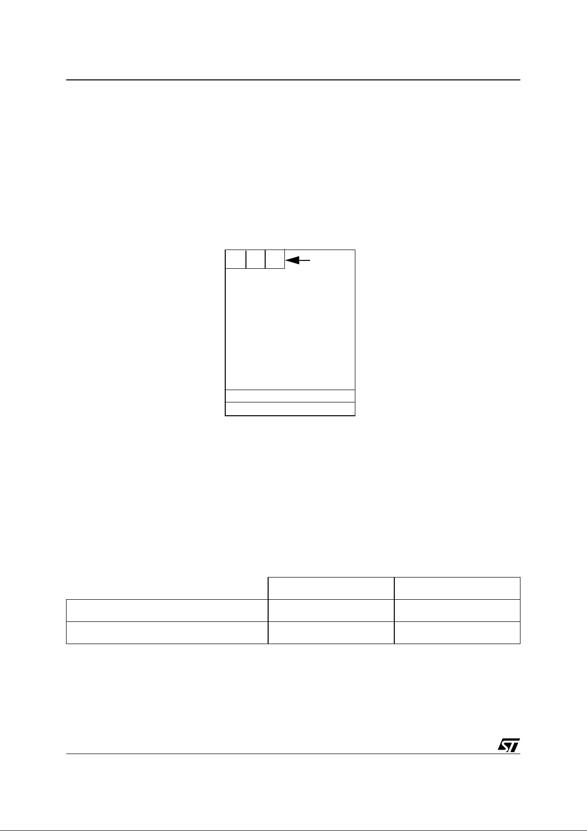
For the ST72F264G2, the checksum is obtained by adding up all the bytes from E003h (beginning of the program stored in FLASH) up to FFFFh. The result is stored in 3 byte variables
(CS0, CS1 and CS2) located at the beginning of the FLASH memory area (from E000 to
E003): a special segment (‘CHECKSUM’ segment) has been created at this location (see
ST72264.asm Mapping file).
E000
CS0 CS1 CS2
checksum
segment
FLASH
(program)
FFE0
FFF0
Interrupt
vectors
It’s very important to chec k the interrupt vectors because to perform the chec ksu m , the reset
vector has to point to the Safe routine and not to the main routine (if FLASH is not checked OK
by the Safe routine, then the user program won’t be run).
The routine which calculates the checksum i s 27 bytes long. The table below shows the calculation times. The time depends on the chosen device (4k or 8k in this case) and on the value
chosen to fill the unus ed me mory a rea ( if the c hosen v alue is $F F for example, ther e will be
more carry to take into account).
Table 1. Checksum Calculation tImes
4k 8k
Device used ST72264G1 ST72264G2
time (ms) 13.7 27.5
The above results have been obtained in the worst case (unused memory part filled with $FF)
with fcpu=8MHz.
2/10
2

ST7 CHECKSUM SELFCHECKING CAPABILITY
Note: There are s ome unused op codes in the ST7 instruction set opcode map which can be
used to make the application more secure. If an unused opcode is put into the unused part of
memory, wrong code won’t be executed if a problem occurs ($AF for instance).
You can also fill the unu sed memory with 0, the opcod e of the NOP ins truction or wh atever
you want.
But what S T ad vis es an d wh at we d o i n our applica tion, is t o fill th e u nus ed par t of m em ory
with the opcode corresponding to the trap execution ($83) allowing recovery through the trap
interrupt routine (which can contain a software reset caused by writi ng the appropriate value in
the watchdog register for instance). See also AN1015: “Software techniques for improving Microcontroller EMC performance”.
3/10
ST7 CHECKSUM SELFCHECKING CAPABILITY
2 USING THE SAME ROUTIN E WI HT A USER’S APPLICATION
2.1 FLASH
To use the safe routine, do the following:
■ Add the “Safe” routine to the application.
■ Select the “define” statement corresponding to the MCU device used in the application.
■ Change the ‘vectit’ segment depending on the device chosen.
■ Modify the reset vector to point to the Safe routine and not to the main one.
■ Include the right .inc mapping file at the beginning of the application.
■ Update the .bat file for the compilation.
■ Generate the .s19 file.
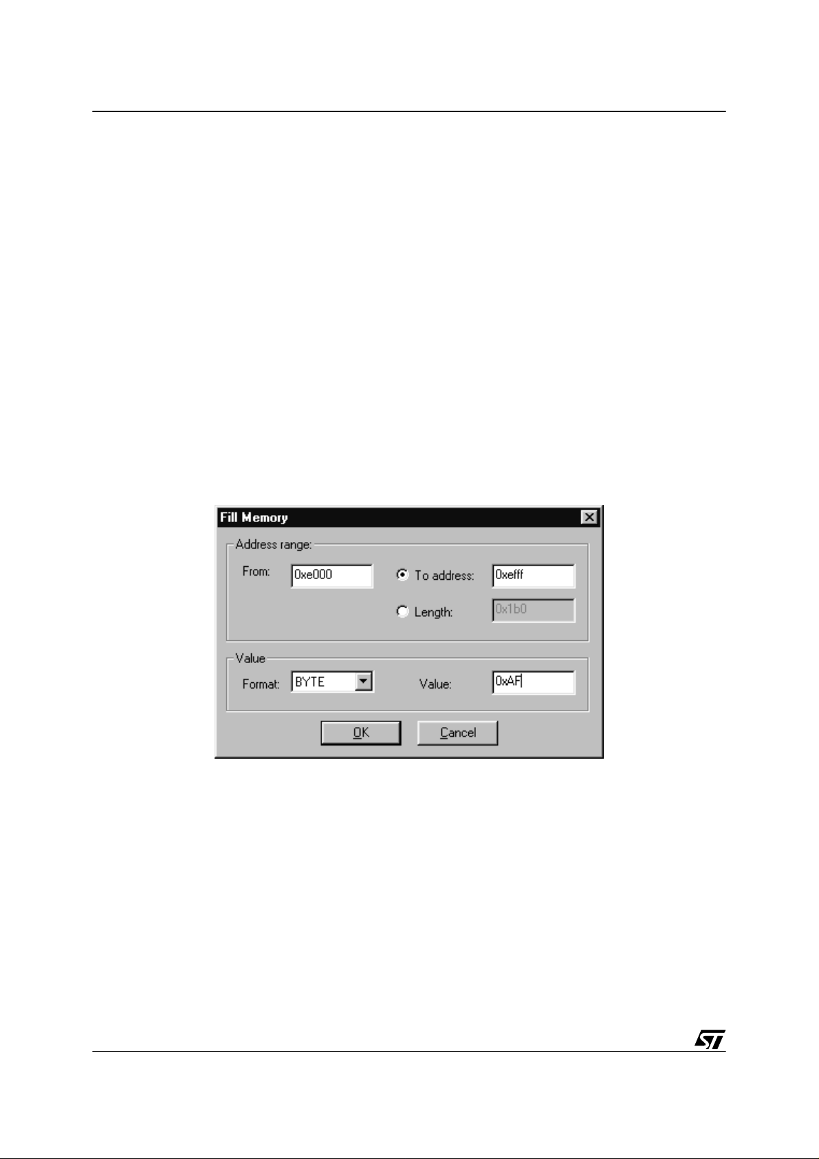
■ Use the emulator or the Development Kit with STVD7: first fill the emulator memory with $83
(for example): before opening the application workspace, go into Debug mode (without any
opened workspace), right-click on the Memory Window and select Fill Memory:
Fill the memory with 0x83 in 2 steps (because there are 2 sectors): first from 0xE000 to
0xEFFF, then from 0xF000 to 0xFFFF. You then just have to open your workspace and your
program will be written into the Flash area that has bee initialized with $83.
To calculate your application checksum:
■ Run the program the first time with the emulator in order to get the checksum: put a
breakpoint on the line after the “end1” label (see safe.asm in the zip file with this application
note).
■ Fill the CS0, CS1, CS2 variables (in constant.asm) with the obtained checksum value stored
in ch_sum (ch_sum, {ch_sum+1}, {ch_sum+2}).
4/10

ST7 CHECKSUM SELFCHECKING CAPABILITY
■ Generate the new .s19 file.
■ Program the FLASH using the EPB Programming Board and fill the unused memory with the
same opcode as before ($83 in our example) using the Edit, Fill area menu in STVisual
Programmer software (STVP7).
2.2 ROM
For the ROM, the principle is the same, but you have to specify the content of the unused
bytes in the program memory.
In order that the stored c hecksum matc hes the c alculated one, the un used bytes have to be
the same. Using the windows programmer (STVP7), fill the unused bytes with a particular opcode (the trap code for instance: 83h), and then save this new complete .s19 file, replacing the
previous one. Otherwise fill the unused bytes directly in the code with using assembly language REPEAT...UNTIL directives. Refer to the “ST7 Assembler-Linker user manual” for
more information on ST7 assembly directives.
5/10
ST7 CHECKSUM SELFCHECKING CAPABILITY
3 DESCRIP TION OF “SAFE” ROUTINE OPERATION
At each reset, the Safe routine calculates the checksum from E003h to FFFFh and compares
it to CS0, CS1 and CS2. If the comparison is OK, the user application (the main routine) will be
run and in our example, the PBDR register is set to FFh (all LEDS set). If the comparison isn’t
OK, the microcontroller is halted (only a reset can make it exit from this state and this means
the user application won’t be run). The halt state (please refer to AN980 for more details) puts
the MCU in its lowest power consumption mode. The internal oscillator is turned off, causing
all internal processing to be stopped, including the operation of the on-chip peripherals.
Note: During the execution of the Safe routine, the I/O lines will be in their reset state (generally floating input) because they won’t have been modified.
If the checksum comparison is not OK, the I/O lines remain unchanged in their reset state.
The main program in our application just switches all LEDs on and then waits in an infinite
loop. You can replace this by your own application.
4 FLOWCHARTS
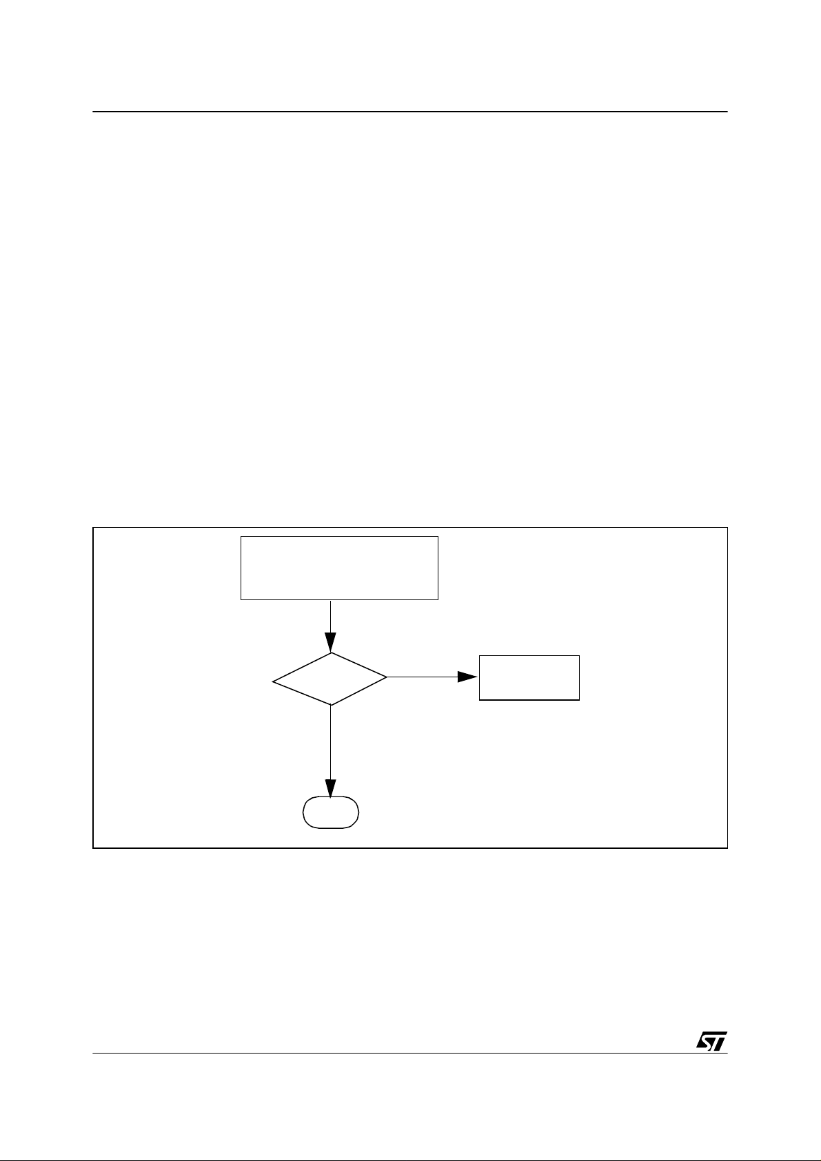
Figure 1. Safe routine (for ST72264G2)
calculate
the checksum
stored into ch_sum
from E003 to FFFF
ch_sum=CS?
no
yes
main
(in our application PBDR=FF
and a delay loop)
with:
■ CS means checksum stored in CSO, CS1 and C S2.
HALT
■ ch_sum is the three byte variable created to store the checksum calculated by the Safe
routine.
6/10
ST7 CHECKSUM SELFCHECKING CAPABILITY
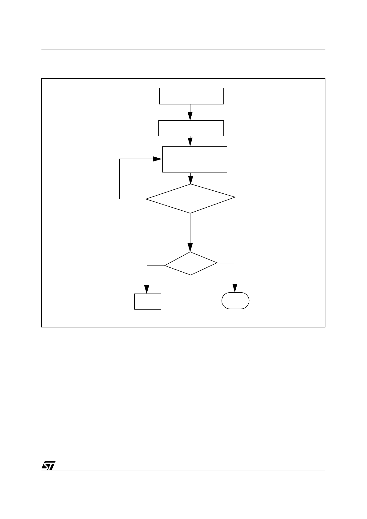
Figure 2. Calculation of the checksum (for ST72264G2)
start_page = E000
A = start_page+X
CALL add_byte
(CS+=current byte)
no
no
HALT
checksum calculated
till FFFF?
yes
yes
ch_sum=CS?
main
7/10

ST7 CHECKSUM SELFCHECKING CAPABILITY
Figure 3. Add_byte Routine
INC X
X = 0?
no
A+=start_page+X
C = 1?
no
RET
yes
yes
{ch_sum+1}+=1
start_page+=100
RET
yes
C = 1?
8/10
no
RET
ch_sum+=1
RET

ST7 CHECKSUM SELFCHECKING CAPABILITY
5 SOFTWARE
All the source files in assembly code are given in the zip file with this application note.
The source files are for guidance only. STMicroelectronics shall not be held liable for any di-
rect, indirect or consequential damages with respect to any claims arising from use of this s oftware.
9/10

ST7 CHECKSUM SELFCHECKING CAPABILITY
“THE PRESENT NOTE WHICH IS FOR GUIDANCE ONLY AIMS AT PROVIDING CUSTOMERS WITH INFORMATION
REGARDING THE IR PRO DUCT S IN OR DER FO R THEM TO SAV E TIME . AS A RES ULT, STMIC ROEL ECTR ONI CS
SHALL NOT BE HELD LIABLE FOR ANY DIRECT, INDIRECT OR CONSEQUENTIAL DAMAGES WITH RESPECT TO
ANY CL AIM S AR IS IN G FR OM T HE CO N TENT OF S UC H A NO TE A ND /O R T HE U SE M AD E BY C US TO ME RS O F
THE INFORMATION CONTAINED HEREIN IN CONNECTION WITH THEIR PRODUCTS.”
Information furnished is believed to be accurate and reliable. However, STMicroelectronics assumes no responsibility for the consequences
of use of such information nor for any infringement of patents or other rights of third parties which may result from its use. No license is granted
by implic ation or otherwise under any patent or patent ri ghts of STM i croelectr oni cs. Spec i fications mentioned i n this publication are subje ct
to change without notice. This publication supersedes and replaces all information previously supplied. STMicroelectronics products are not
authorized for use as cri tical comp onents in life support dev i ces or systems wi thout the express written approv al of STMicroel ectronics.
The ST logo is a registered trademark of STMicroelectronics
2002 STMicroelectronics - All Rights Reserved.
STMicroelectronics Group of Compan i es
http://www.s t. com
Purchase of I
2
C Components by STMicroelectronics conveys a license under the Philips I2C Patent. Rights to use the se components in an
2
I
C system i s granted pro vi ded that the sy stem conforms to the I2C Standard Specification as defined by Philips.
Australi a - B razil - Canada - China - Finl and - France - Germany - Hong Kong - Ind ia - Israel - Italy - Japan
Malaysi a - M al ta - Morocco - Singapore - Spain - Sw eden - Switz erland - United Kingdom - U.S.A.
10/10
 Loading...