

Page 1

AN1045
APPLICATION NOTE
ST7 S/W IMPLEMENTATION OF I2C BUS MASTER
by Microcontroller Division Applications Team
INTRODUCTION
The goal of this application note is to i mplement an I2C communications software interface for
devices which have no I2C perip heral. The software of this app lication perform s I2C master
transmitter and master receiver functions. The master chosen here is a ST72324 and the
slave is an EEPROM (M24C08).
The program described in this a pplication note is in C language, a program in assembly language is also available in the software library (see ST7 CD ROM on Internet).
1 CHARACTERISTICS
The main characteristics of this I2C software are:
■ bit addressing
■ Master Transmitter/Receiver
■ Several data bytes sent and received (3 in this application)
■ Fscl = 62.5 kHz
■ Acknowledge management
■ Error management (AF)
The I2C synchronous communication needs only two signals: SCL (Serial clock line) and SDA
(Serial data line). The corresponding port pins used are PA7 for SCL and PA6 for SDA.
These two pins are configured as floating input (to have a high level applied on the pin or to receive data) or as output open drain (to have a low level applied on the pin or to output data).
Please refer to the ST7 datasheet for more details about port configuration.
AN1045/0803 1/16
1
Page 2
ST7 S/W IMPLEMEN TATION OF I2C BU S MASTER
1.1 COMMUNICATION SPEED
The comm unic ation spee d is m odifiabl e by usin g the fun ction delay(t ime) w hich waits for a
given time period and then modifies the frequency of SCL.
Here Fscl is equal to 62.5 kHz. It can be easily reduced by increasing the period between two
clock cycles, but this speed is not far from the highest speed you can have (~70 kHz).
1.2 START, STOP CONDITION AND ACKNOWLEDGE GENERATION
The Start and Stop conditions are always generated by the master. In this software, there are
no bits to set to generate these conditions like in the real peripheral: you just have to call the
corresponding function (I2Cm_Start() and I2Cm_Stop()).
An Acknowledge is sent after an address or a data byte is received. When the master has to
receive an acknowledge from the slave, you have to call the function Wait_Ack() which reads
the SDA and SC L lines to reco gnize the acknowl edge condition (the S DA line put at the low
state by the one which sends the acknowledge during one clock pulse). And when the master
has to send an acknowledge after receiving data from the slave, you have to call the function
I2Cm_Ack().
2 ST7 I2C COMMUNICATION APPLICATION
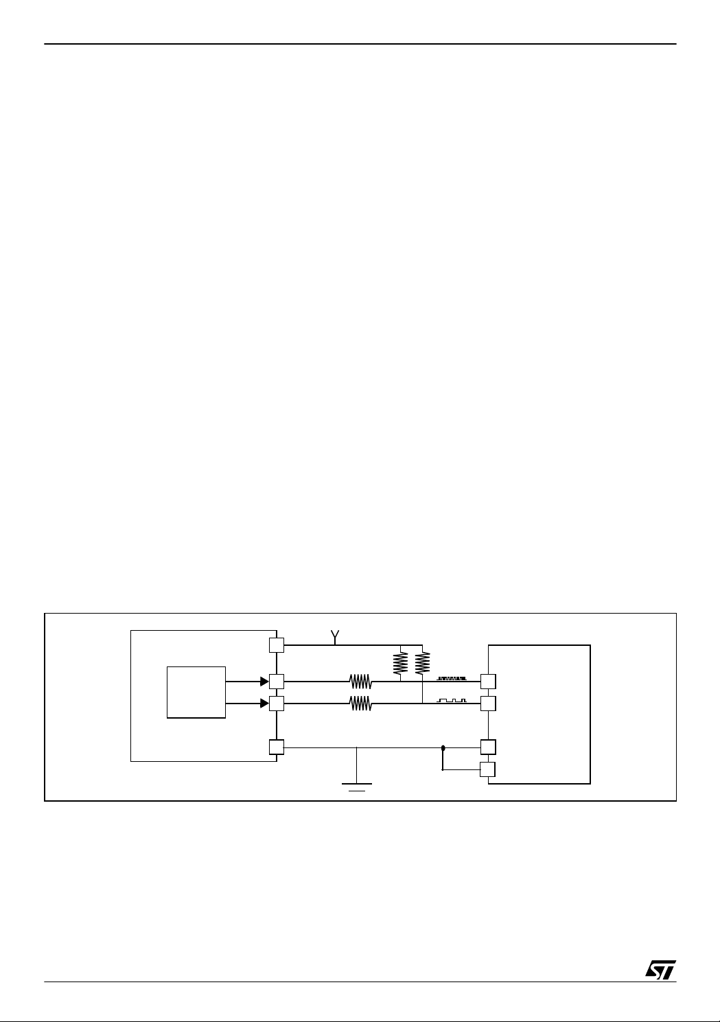
2.1 HARDWARE CONFIGURATION
The ST7 communication application hardware is composed of a ST72324 microcontroller
(which has no I2C peripheral) and any slave (an M24C08 EEPROM for example).
Figure 1. ST7 / E2PROM I2C Communication A pp lication
5V
SCL
SDA
Vdd
Vss
2x100W
2x12KW
M24C08
SCL
SDA
Vss
E
ST72324
I2C
2/16
2
Page 3

ST7 S/W IMPLEMENTATION OF I2C BUS MASTER
2.2 INITIATING A COM MUNICATION
To initiate an I2C communication, first a start condition has to be generated and then the selected slave address has to be sent, both by the master.
Here, this action i s don e b y calling the fun ction I2C m_S tart() fol lowed by th e sen din g of the
slave address with the least significant bit correctly set (0:transmission, 1:reception).
As the slave here is an EEPR OM, two addresses have to be sent by the master to the slave:
the address of the slave and the address w here y ou want to write or read into the EE PR OM
(refer to Section 3: Communication frames).
2.3 SENDING A DATA BYTE ON THE I2C BUS
To transmit a new data byte from the ST72324, the addresses or data bytes previously transmitted have to be completed correctly. This previous byte transmission check is done with the
reception of an acknowledge condition by the master. If an er ror is detected ( AF: Acknowledge
Failure), the AF bit of the created I2C_SR2 register is cleared and the transmission is restarted from the START condition.
When the prev ious dat a t ransmis sion is over, the app lication w rites the new data by te to be
transmitted. The d ata t o transm it is p ut on the created I2 C_ DR r egister an d is sent bi t by b it
through PADR (PA6=SDA), MSB first.
All the data to send to the slave (and the addresses too) are stored in a table.
2.4 RECEIVING A DATA BYTE ON THE I2C BUS
To receive a new data byte, the previous data byte to receive has to be c ompleted correctly.
This byte rece ption chec k is done with the send ing of an ackn owledge cond ition by the
master. An AF can’t occur on the master side because it’s the master that sends the acknowledge condition. If there is a problem with the reception of this acknowledge, it’s up to the slave
to manage this problem.
The frame in thi s case (m aster receiver ) is: the mas ter after sendin g th e first Start c ond ition
and the two addresses, has to resend a Start condition followed by the address of the
EEPROM, but this time with the least sign ificant bit at 1 to make the slave understand it’s
waiting for the data (refer to Section 3: Communication frames).
When the master is receiver, after receiving the last data, it has to generate a non acknowledge condition to be able to generate the STOP condition afterwards.
Note: There is no need to clear the ACK bit to disable acknowledgement before receiving the
second last byte or set the STOP bit before receiving the last byte (as is necessary in ST7
MCUs with a dedicated I2C peripheral), because here Acknowledgement and Stop condition
generation is under software control, while in the I2C Peripheral it is under hardware control.
3/16
Page 4
ST7 S/W IMPLEMEN TATION OF I2C BU S MASTER
3 COMMUNICATION FRAMES
The communication protocol between the master and the slave is given in Figure 2. For more
details, please refer to the ST7 datasheet.
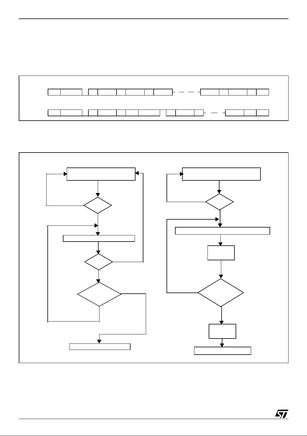
Figure 2. I2C Communication Protocol
Write data from ST7 to E2PROM
E2PROM @
START
ACK
SUB @ ACK DATA 1 ACK DATA 2 ACKDATA N-1 DATA N
Read data from E2PROM to ST7
E2PROM @
START
ACK
SUB @ ACK DATA 1 ACK DATA N NACK
START
E2PROM @
ACK
ACK
STOP
STOP
4 FLOWCHARTS
Figure 3. Communication Application Flowchart
Master transmitter Master receiver
INITIATE TRANSMIS SION
(START + addresses)
no
ACK?
yes
SEND NEXT TABLE DATA
ACK?
no
yes
END OF
yes
BUFFOUT?
no
INITIATE TRANSMISSION
(START+@+START+@lsb=1)
no
ACK?
yes
WAIT FOR NEXT DATA TO RECEIVE
ACK
no
LAST VALUE
TO RECEIVE?
yes
NON ACK
4/16
STOP CONDITIO N
STOP CONDITIO N
Page 5
ST7 S/W IMPLEMENTATION OF I2C BUS MASTER
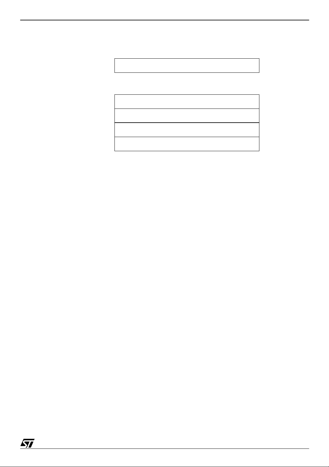
Figure 4. Buffer of transmission structure
0 data nb-2
|
|
nb-3 data2
nb-2 data1
nb-1 sub @
nb EEPROM @
|
|
The buffer of transmission contains the EEPROM address, the sub addr ess (the address
where you want to write into the EEPROM) and then the data to transmit.
In this application, a parameter called “n” allows you to modify the number of data to transm it
and then to receive. The number of data is “n-1”, that means that in this application, as 3 data
have to be sent, “n=4”.
The transm ission fu nction is base d on a double s hift: a shift of the “coun t” variabl e to call 8
times the function I2Cm_TxData (to send the 8 bits of one data byte) and a shift into the
I2Cm_TxData function to always send the MSB of the data (refer to Figure 5).
5/16
Page 6

ST7 S/W IMPLEMEN TATION OF I2C BU S MASTER
Figure 5. Flowchart of the transmission function
SDA configured as output
j=nb
count=1
I2C_DR=buffout[j]
shift of count
I2Cm_TxData
no
count overflows?
wait Acknowledge
ACK ok?
no
yes
yes
j--
j=FF?
yes
no
AF=1
END
The reception function is also based on a double shift: a s hift of the “count” va riable to call 8
times the function I2Cm_RxData (to receive the 8 bits of one data byte) and a shift of a buffer
into the I2Cm_RxData function to receive the data bit by bit on the LSB (refer to Figure 6).
6/16
Page 7

ST7 S/W IMPLEMENTATION OF I2C BUS MASTER
Figure 6. Flowchart of the reception function
RCPT=1
I2Cm_Tx for addresses
transmission
SDA configured as input
yes
AF?
no
count=1
j--
shift of count
I2Cm_RxData
no
no
count overflows?
yes
j=FF?
no
SDA configured as output
Acknowledge
END
buffin[j]=I2C_DR
7/16
Page 8

ST7 S/W IMPLEMEN TATION OF I2C BU S MASTER
5 SOFTWARE
The assembly code given below is for guidance only.
/**************** (c) 2003 STMicroelectronics ********************************
PROJECT : EVALUATION BOARD - ST7 I2C DEMO SYSTEM
COMPILERS : COSMIC AND METROWERKS
MODULE : i2cm_drv.c
REVISION DATE : 12/06/03
AUTHOR : Micro Controller Division Application Team
-*-*-*-*-*-*-*-*-*-*-*-*--*-*-*-*-*-*-*-*-*-*-*-*-*-*-*-*-*-*-*-*-*-*-*-*-*-
THE SOFTWARE INCLUDED IN THIS FILE IS FOR GUIDANCE ONLY. STMicroelectronics
SHALL NOT BE HELD LIABLE FOR ANY DIRECT, INDIRECT OR CONSEQUENTIAL
DAMAGES WITH RESPECT TO ANY CLAIMS ARISING FROM USE OF THIS SOFTWARE.
-*-*-*-*-*-*-*-*-*-*-*-*--*-*-*-*-*-*-*-*-*-*-*-*-*-*-*-*-*-*-*-*-*-*-*-*-*-
DESCRIPTION : ST7 I2C single master T/R peripheral software driver.
-*--*-*-*-*-*-*-*-*-*-*-*-*-*-*-*-*-*-*-*-*-*-*-*-*-*-*-*-*-*-*-*-*-*-*-*-*-
MODIFICATIONS :
27/08/98 - V1.0 - First version (error management:AF).
12/06/03 - V1.1 - 1) Compatibility With Cosmic And Metrowerks.
2) Generation Of Non - Ack.
3) Update for st72324
**************************************************************************/
#pragma NO_STRING_CONSTR
#define SDA 6
#define SCL 7
/* EXTERNAL DECLARATIONS ***************************************************/
/* List of all the variables defined in another module and used in this one. */
/* MODEL => #include {file_name}.h */
#include "map72324.h" /* Declaration of the I2C HW registers.*/
#include "lib_bits.h" /* Bit handling macro definitions.*/
#include "variable.h"
/* FUNCTIONDESCRIPTIONS ************************************************* /
/* Description of all the functions defined in this module. */
8/16
Page 9

ST7 S/W IMPLEMENTATION OF I2C BUS MASTER
/* MODEL => [static] type_name var_name; or #define */
void delay (unsigned char time)
{
#ifdef __HIWARE__
asm
{
nop /* Time is stored on the Accumulator automatically */
again: DEC A /* When the function is called. */
JRNE again /* (15+6*time) clock cycles */
}
#else
#ifdef __CSMC__
{
_asm ("nop");
_asm("again: DEC A");
_asm(" JRNE again");
}
#endif
#endif
}
/*-------------------------------------------------------------------------ROUTINE NAME : I2Cm_Start
INPUT/OUTPUT : None.
DESCRIPTION : Generates I2C-Bus Start Condition.
COMMENTS :
--------------------------------------------------------------------------*/
void I2Cm_Start (void)
{
ClrBit(PADDR,SDA);
/* Configure SDA and SCL as floating input to have a high state */
ClrBit(PADDR,SCL);
delay(10);
SetBit(PADDR,SDA);
/* Configure SDA as output open drain to have a low state */
delay(4);
/* Waits 39 cycles=4.875µs at a Fcpu=8MHz to keep the high state on SCL */
SetBit(PADDR,SCL);
/* Configure SCL as output open drain to have a low state */
delay(6); /* Delay to wait after a START */
}
/*-------------------------------------------------------------------------ROUTINE NAME : I2Cm_Stop
9/16
Page 10

ST7 S/W IMPLEMEN TATION OF I2C BU S MASTER
INPUT/OUTPUT : None.
DESCRIPTION : Generates I2C-Bus Stop Condition.
COMMENTS :
--------------------------------------------------------------------------*/
void I2Cm_Stop (void)
{
SetBit(PADDR,SDA);
/* Configure SDA and SCL as output open drain to have a low state */
SetBit(PADDR,SCL);
ClrBit(PADDR,SCL);
/* Configure SCL as floating input to have a high state */
delay(4); /* Macro delay with time=4 (4.875 µs) */
ClrBit(PADDR,SDA);
/* Configure SDA as floating input to have a high state */
/* Delay after the Stop did in main.c with Wait_1ms() */
}
/*-------------------------------------------------------------------------ROUTINE NAME : wait_Ack
INPUT/OUTPUT : None.
DESCRIPTION : Acknowledge received?
COMMENTS : Transfer sequence = DATA, ACK.
--------------------------------------------------------------------------*/
void wait_Ack (void)
{
SetBit(PADDR,SCL); /* Output open drain to have a low level */
ClrBit(PADDR,SDA); /* Floating input, the slave has to pull SDA low */
delay(1);
if (ValBit(PADR,SDA)) /* Test of SDA level, if high -> pb */
{
SetBit(I2C_SR2,AF);
ClrBit(I2C_SR1,ACK);
return;
}
delay(2);
if (ValBit(PADR,SDA)) /* Test of SDA level, if high -> pb */
{
SetBit(I2C_SR2,AF);
ClrBit(I2C_SR1,ACK);
return;
}
delay(5);
ClrBit(PADDR,SCL); /* Start of the generation of 1 clock pulse */
delay(1);
if (ValBit(PADR,SDA)) /* Test of SDA level, if high -> pb */
{
10/16
Page 11

ST7 S/W IMPLEMENTATION OF I2C BUS MASTER
SetBit(I2C_SR2,AF);
ClrBit(I2C_SR1,ACK);
return;
}
delay(1);
if (ValBit(PADR,SDA)) /* Test of SDA level, if high -> pb */
{
SetBit(I2C_SR2,AF);
ClrBit(I2C_SR1,ACK);
return;
}
delay(1);
SetBit(PADDR,SCL); /* End of the clock pulse */
SetBit(I2C_SR1,ACK);
delay(1);
ClrBit (PADR,SDA);
SetBit(PADDR,SDA);
/* Reconfigure SDA as output to proceed at the next transmission */
}
/*-------------------------------------------------------------------------ROUTINE NAME : I2C_nAck
INPUT/OUTPUT : None.
DESCRIPTION : Non acknoledge generation from now.
COMMENTS : Transfer sequence = DATA, NACK.
--------------------------------------------------------------------------*/
void I2C_nAck (void)
{
ClrBit(I2C_SR2,ACK); /* Non acknoledge when the master is receiver */
SetBit(PADR,SDA); /* The master pulls the SDA line high */
SetBit(PADDR,SCL); /* Output open drain to have a low level */
delay(10);
ClrBit(PADDR,SCL); /* The master generates a clock pulse */
delay(10);
SetBit(PADDR,SCL); /* Clock pulse complete */
ClrBit(PADR,SDA); /* The master pulls the SDA line high */
delay(3);
}
/*-------------------------------------------------------------------------ROUTINE NAME : I2Cm_Init
INPUT/OUTPUT : None.
DESCRIPTION : I2C peripheral initialisation routine.
COMMENTS : Contains inline assembler instructions in C like mode !
--------------------------------------------------------------------------*/
void I2Cm_Init (void)
11/16
Page 12

ST7 S/W IMPLEMEN TATION OF I2C BU S MASTER
{
count=0;
I2C_SR1=0;
I2C_SR2=0;
I2C_DR=0;
err_status=0;
t_count_err=0;
r_count_err=0;
SetBit(I2C_SR1,M_SL); /* Master mode: M_SL=1 */
}
/*-------------------------------------------------------------------------ROUTINE NAME : I2Cm_TxData
INPUT/OUTPUT : data byte to be transfered(MSB first) / None.
DESCRIPTION : Transmits a data bit.
COMMENTS : Transfer sequence = DATA, ACK, ...
--------------------------------------------------------------------------*/
void I2Cm_TxData (void)
{
SetBit(PADDR,SCL); /* Low level on SCL */
if (I2C_SR2) /* Check the communication error status */
{
err_status++;
t_count_err++;
if (t_count_err==0) t_count_err++;
}
else /* If no error */
{
if (ValBit(I2C_DR,7)) /* Send data bit per bit, MSB first */
SetBit(PADR,SDA); /* Send a one */
else
ClrBit(PADR,SDA); /* Send a zero */
I2C_DR*=2;
ClrBit(PADDR,SCL); /* High state on SCL */
delay(10);
}
}
/*-------------------------------------------------------------------------ROUTINE NAME : I2Cm_RxData
INPUT/OUTPUT : Last byte to receive flag (active high) / Received data bit.
DESCRIPTION : Receive a data byte.
COMMENTS : Transfer sequence = DATA, ACK, EV7...
--------------------------------------------------------------------------*/
void I2Cm_RxData (void)
12/16
Page 13

ST7 S/W IMPLEMENTATION OF I2C BUS MASTER
{
if (!I2C_SR2) /* No communication error detected */
{
buff*=2; /* Shift I2C_DR to receive next bit */
#ifdef __HIWARE__
asm
{
nop
nop
nop
}
#else
#ifdef __CSMC__
{
_asm("nop");
_asm("nop");
_asm("nop");
}
#endif
#endif
ClrBit(PADDR,SCL); /* Rise the SCL line */
do{
}while(ValBit(PADR,SCL)!=0); /* Wait SCL at a high state */
if(ValBit(PADR,SDA))
buff|=1; /* The received bit is 1 */
else
buff|=0; /* The received bit is 0 */
delay(10);
SetBit(PADDR,SCL); /* SCL at a low level */
}
else
r_count_err++;
}
/*-------------------------------------------------------------------------ROUTINE NAME : I2C_Ack
INPUT/OUTPUT : None.
DESCRIPTION : Send Ack to the slave.
COMMENTS :
--------------------------------------------------------------------------*/
void I2C_Ack(void)
{
ClrBit(PADR,SDA); /* The master pulls the SDA line low */
13/16
Page 14

ST7 S/W IMPLEMEN TATION OF I2C BU S MASTER
SetBit(PADDR,SDA);
delay(10);
ClrBit(PADDR,SCL); /* Waits the master takes the control of SDA */
delay(10);
SetBit(PADDR,SCL);
delay(5);
ClrBit(PADDR,SDA); /* The master releases the SDA line */
SetBit(I2C_SR1,ACK); /* ACK=1: Acknowledge sent by the master */
}
/*-------------------------------------------------------------------------ROUTINE NAME : I2Cm_Tx
INPUT/OUTPUT : send_tab and n, the number of data to transmit (with 2 addresses)
/ None.
DESCRIPTION : Transmit data buffer.
COMMENTS : Most significant bytes first.
--------------------------------------------------------------------------*/
void I2Cm_Tx (char * buffout,char nb)
{
SetBit(PADDR,SDA); /* Configure SDA as an output to send data */
for (j=nb;j!=0xFF;j--)
{ /* 2 addresses and 3 data to send: from X=n downto X=0 */
flag=0;
if ((j==(nb-2))&&(ValBit(I2C_SR1,RCPT)))
{
I2Cm_Start(); /* Start condition */
j=nb; /* EEPROM @ with the LSB at 1 to send */
flag=1;
}
count=1;
I2C_DR=buffout[j];
if (flag==1) I2C_DR=I2C_DR|1;
/* If master receiver, the address to send is A1 */
do
{
I2Cm_TxData(); /* Sending of data bit per bit, MSB first */
count*=2;
}while(count!=0);
wait_Ack(); /* Wait ACK from the slave */
if(!ValBit(I2C_SR1,ACK))
SetBit(I2C_SR2,AF);
14/16
Page 15

ST7 S/W IMPLEMENTATION OF I2C BUS MASTER
if (flag==1) return;
/* If master receiver, go back to I2Cm_Rx() to receive data */
}
}
/*-------------------------------------------------------------------------ROUTINE NAME : I2Cm_Rx
INPUT/OUTPUT : @ reception buffer + n-2 data/ None.
DESCRIPTION : Receive in data buffer via I2C.
COMMENTS : Most significant bytes first.
--------------------------------------------------------------------------*/
void I2Cm_Rx (char *buffin,char nb)
{
SetBit(I2C_SR1,RCPT); /* Master in receiver mode */
I2Cm_Tx(send_tab,nb); /* Send the addresses and wait ACK */
if (ValBit(I2C_SR2,AF)) return;
/* If AF -> go back to main and restart the reception */
for (j=nb-2;j!=0xFF;j--)
{
count=1;
buff=0;
ClrBit(PADDR,SDA);
/* SDA as floating input to read data from the EEPROM */
do
{
I2Cm_RxData(); /* Read data bit per bit, MSB first */
count*=2;
}while(count!=0);
I2C_DR=buff;
SetBit(PADDR,SDA); /* Configure SDA as output */
if (j==0)
I2C_nAck();
/* Non acknowledge to make the master generate the STOP */
else
I2C_Ack(); /* To acknowledge read data */
buffin[j]=I2C_DR; /* Store read data into buffin */
}
}
/******************* (c) 2003 STMicroelectronics ************ END OF FILE ***/
15/16
Page 16

ST7 S/W IMPLEMEN TATION OF I2C BU S MASTER
THE PRESENT NOTE WHICH IS FOR GUIDANCE ONLY AIMS AT PROVIDING CUSTOMERS WITH INFORMATION
REGARDING THE IR PRO DUCT S IN OR DER FO R THEM TO SAV E TIME . AS A RES ULT, STMIC ROEL ECTR ONI CS
SHALL NOT BE HELD LIABLE FOR ANY DIRECT, INDIRECT OR CONSEQUENTIAL DAMAGES WITH RESPECT TO
ANY CL AIM S AR IS IN G FR OM T HE CO N TENT OF S UC H A NO TE A ND /O R T HE U SE M AD E BY C US TO ME RS O F
THE INFORMATION CONTAINED HEREIN IN CONNECTION WITH THEIR PRODUCTS.
Information furnished is believed to be accurate and reliable. However, STMicroelectronics assumes no responsibility for the consequences
of use of such information nor for any infringement of patents or other rights of third parties which may result from its use. No license is granted
by implic ation or otherwise under any patent or p atent rights of STMi croelectroni cs. Specifications mentioned in thi s publicati on are subject
to change without notice. This publication supersedes and replaces all information previously supplied. STMicroelectronics products are not
authorized for use as cri tical comp onents in life support dev i ces or systems wi t hout the exp ress written approval of STM i croelectronics.
The ST logo is a registered trademark of STMicroelectronics
2003 STMicroelectronics - All Rights Reserved.
STMicroelectronics Group of Compan i es
http://www.s t. com
Purchase of I
2
C Components by STMicroelectronics conveys a license under the Philips I2C Patent. Rights to use the se components in an
2
I
C system i s granted pro vided that th e sy stem confo rm s to the I2C Standard Specification as defined by Philips.
Australi a - B razil - Canada - China - Finl and - France - Germany - Hong Kong - Ind i a - Is rael - Ital y - J apan
Malaysi a - M al ta - Morocco - Singapore - Spain - Sw eden - Switz erland - Unit ed Kingdom - U.S.A.
16/16
 Loading...