

Page 1
AN1012
Application note
Predicting the battery life and data
retention period of NVRAMs and serial RTCs
Introduction
Standard SRAM devices have the advantage, over EEPROM and Flash memory, of high
write-speed when used as main memory for a processor or microcontroller. Their
disadvantage is that they are volatile, and lose their contents as soon as the power supply is
removed (whether this is for a prolonged period due to being turned off, or due to an
unexpected glitch or loss of the power supply).
STMicroelectronics manufactures a line of non-volatile SRAMs (NVRAMs), known as
ZEROPOWER
best of both worlds: memory devices that are non-volatile like EEPROM, yet have the fast
access of SRAM. These devices consist of an array of low-power CMOS SRAM, plus a
small long-life lithium power cell (along with a high-accuracy quartz crystal, in the case of
the TIMEKEEPER). While the external power supply is within its specified limits, the
memory behaves as standard SRAM; but as soon as the external power supply strays out of
tolerance, the SRAM becomes write-protected, and its contents are preserved by a small
trickle current supplied by the internal power cell.
Unlike EEPROM, where the data contents are guaranteed to be preserved for 10 years (and
typically last for much longer), the contents of NVRAM will only be retained while the internal
cell is able to supply sufficient current to maintain the array. This document summarizes the
factors involved in predicting the battery life, and consequently data retention under various
operating conditions.
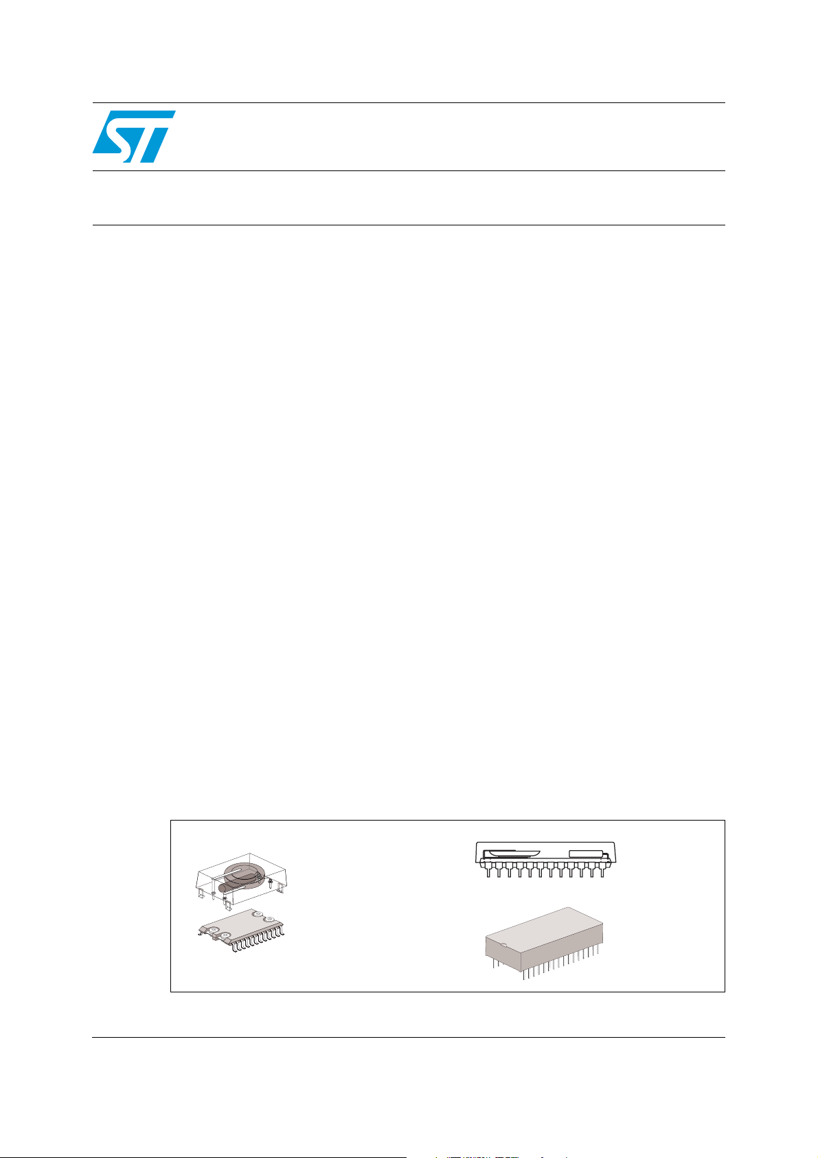
Many of the ZEROPOWER, TIMEKEEPER, supervisor, and serial RTC devices are
packaged in a 600 mil DIP CAPHAT™, a hybrid DIP, or a 330 mil SOIC SNAPHAT
SNAPHAT (shown in Figure 1) has a removable top that includes both the long-life lithium
cell and, in the case of the TIMEKEEPER, a high-accuracy crystal.
STMicroelectronics has shipped several million SNAPHATs that have been used in a broad
range of applications. From PC-based systems to high-end workstations,
telecommunications, consumer, and automotive applications, these products have provided
highly reliable data storage for the electronics industry.
®
or TIMEKEEPER® NVRAMs, supervisors, and serial RTCs which offer the
®
. The
Figure 1. Standard ZEROPOWER, TIMEKEEPER, supervisor, and serial RTC
packages
CAPHAT™
SOIC and SNAPHAT® To p
Hybrid DIP
September 2011 Doc ID 6395 Rev 4 1/33
www.st.com
Page 2

Contents AN1012
Contents
1 Process technology . . . . . . . . . . . . . . . . . . . . . . . . . . . . . . . . . . . . . . . . . 6
2 Battery technology . . . . . . . . . . . . . . . . . . . . . . . . . . . . . . . . . . . . . . . . . . 7
3 Battery backup current - predicting data retention time . . . . . . . . . . . . 8
3.1 Storage life . . . . . . . . . . . . . . . . . . . . . . . . . . . . . . . . . . . . . . . . . . . . . . . . . 8
3.2 Calculating storage life . . . . . . . . . . . . . . . . . . . . . . . . . . . . . . . . . . . . . . . . 9
3.3 Capacity consumption . . . . . . . . . . . . . . . . . . . . . . . . . . . . . . . . . . . . . . . 10
3.4 Calculating capacity consumption . . . . . . . . . . . . . . . . . . . . . . . . . . . . . . 10
4 4T cell devices . . . . . . . . . . . . . . . . . . . . . . . . . . . . . . . . . . . . . . . . . . . . . 11
5 TIMEKEEPER products . . . . . . . . . . . . . . . . . . . . . . . . . . . . . . . . . . . . . . 12
5.1 TIMEKEEPER® register map . . . . . . . . . . . . . . . . . . . . . . . . . . . . . . . . . . 13
5.2 TIMEKEEPER
5.2.1 M48T02 and M48T12 . . . . . . . . . . . . . . . . . . . . . . . . . . . . . . . . . . . . . . 14
5.2.2 M48T08 and M48T18 . . . . . . . . . . . . . . . . . . . . . . . . . . . . . . . . . . . . . . 15
5.2.3 M48T58 . . . . . . . . . . . . . . . . . . . . . . . . . . . . . . . . . . . . . . . . . . . . . . . . . 16
5.2.4 M48T35 and M48T37V/Y . . . . . . . . . . . . . . . . . . . . . . . . . . . . . . . . . . . . 17
®
evolution . . . . . . . . . . . . . . . . . . . . . . . . . . . . . . . . . . . . . 14
6 Supervisor products . . . . . . . . . . . . . . . . . . . . . . . . . . . . . . . . . . . . . . . . 19
7 Choosing SRAM . . . . . . . . . . . . . . . . . . . . . . . . . . . . . . . . . . . . . . . . . . . 20
8 Industrial temperature devices . . . . . . . . . . . . . . . . . . . . . . . . . . . . . . . 22
9 U.L. recognition and recycling . . . . . . . . . . . . . . . . . . . . . . . . . . . . . . . . 23
10 Summary . . . . . . . . . . . . . . . . . . . . . . . . . . . . . . . . . . . . . . . . . . . . . . . . . 24
Appendix A Product data. . . . . . . . . . . . . . . . . . . . . . . . . . . . . . . . . . . . . . . . . . . . 25
Appendix B ZEROPOWER products . . . . . . . . . . . . . . . . . . . . . . . . . . . . . . . . . . . 26
®
Appendix C TIMEKEEPER
2/33 Doc ID 6395 Rev 4
products . . . . . . . . . . . . . . . . . . . . . . . . . . . . . . . . . . 28
Page 3

AN1012 Contents
Appendix D Serial RTC products . . . . . . . . . . . . . . . . . . . . . . . . . . . . . . . . . . . . . 30
11 Revision history . . . . . . . . . . . . . . . . . . . . . . . . . . . . . . . . . . . . . . . . . . . 32
Doc ID 6395 Rev 4 3/33
Page 4

List of tables AN1012
List of tables
Table 1. ZEROPOWER and TIMEKEEPER® product categories . . . . . . . . . . . . . . . . . . . . . . . . . . . 6
Table 2. Typical TIMEKEEPER (M48T37V/Y) register map . . . . . . . . . . . . . . . . . . . . . . . . . . . . . . . 13
Table 3. Typical I
Table 4. SNAPHAT part numbers. . . . . . . . . . . . . . . . . . . . . . . . . . . . . . . . . . . . . . . . . . . . . . . . . . . 18
Table 5. M40Z300W (120mAh SNAPHAT) data retention life vs. SRAM type . . . . . . . . . . . . . . . . . 20
Table 6. M48T201V/Y (120 mAh SNAPHAT) data retention life vs. SRAM type . . . . . . . . . . . . . . . 21
Table 7. Data for ZEROPOWER
Table 8. Data from hybrid/module devices (V
Table 9. Data from M48Z02/12 devices (available only in CAPHAT™ - BR1225,
48 mAh) . . . . . . . . . . . . . . . . . . . . . . . . . . . . . . . . . . . . . . . . . . . . . . . . . . . . . . . . . . . . . . . 26
Table 10. Data from M48Z08/18, M48Z58, and M48Z58Y devices . . . . . . . . . . . . . . . . . . . . . . . . . . 26
Table 11. Data from M48Z35/Y/AV devices . . . . . . . . . . . . . . . . . . . . . . . . . . . . . . . . . . . . . . . . . . . . 27
Table 12. Data from M48T02/12 devices (available only in CAPHAT™ - BR1632,
120 mAh) . . . . . . . . . . . . . . . . . . . . . . . . . . . . . . . . . . . . . . . . . . . . . . . . . . . . . . . . . . . . . . 28
Table 13. Data from M48T08/Y/18 and M48T58/Y devices . . . . . . . . . . . . . . . . . . . . . . . . . . . . . . . . 28
Table 14. Data from M48T35/Y/AV and M48T37V/Y devices . . . . . . . . . . . . . . . . . . . . . . . . . . . . . . 29
Table 15. Data from M41T56/94, M41ST85W, M41ST87W/Y, and M41ST95W ind. temp. (MH6)
devices . . . . . . . . . . . . . . . . . . . . . . . . . . . . . . . . . . . . . . . . . . . . . . . . . . . . . . . . . . . . . . . . 30
Table 16. Data from M41T00/S, M41T11, and M41T81/S industrial temperature (MH6) devices . . . 31
Table 17. Document revision history . . . . . . . . . . . . . . . . . . . . . . . . . . . . . . . . . . . . . . . . . . . . . . . . . 32
current for TIMEKEEPER devices . . . . . . . . . . . . . . . . . . . . . . . . . . . . . . . . . 13
BAT
®
and TIMEKEEPER® devices . . . . . . . . . . . . . . . . . . . . . . . . . . . 25
duty cycle = 0%) . . . . . . . . . . . . . . . . . . . . . . . . . . 25
CC
4/33 Doc ID 6395 Rev 4
Page 5

AN1012 List of figures
List of figures
Figure 1. Standard ZEROPOWER, TIMEKEEPER, supervisor, and serial RTC packages. . . . . . . . . 1
Figure 2. Four-transistor (4T) SRAM cell . . . . . . . . . . . . . . . . . . . . . . . . . . . . . . . . . . . . . . . . . . . . . . . 6
Figure 3. (A) BR1225 discharge rate and (B) BR1632 discharge rate. . . . . . . . . . . . . . . . . . . . . . . . . 7
Figure 4. Predicted battery storage life versus temperature . . . . . . . . . . . . . . . . . . . . . . . . . . . . . . . . 9
Figure 5. Block diagram of a TIMEKEEPER
Figure 6. M48T02/12 data retention lifetime vs. temperature (120 mAh, 100% battery backup). . . . 14
Figure 7. M48T08/18 data retention lifetime vs. temperature (120 mAh, 100% battery backup). . . . 15
Figure 8. M48T58 data retention lifetime vs. temperature (48 mAh, 100% battery backup) . . . . . . . 16
Figure 9. M48T58 data retention lifetime vs. temperature (120 mAh, 100% battery backup) . . . . . . 16
Figure 10. M48T35/37V/37Y data retention lifetime vs. temperature (48 mAh, 100% battery backup)17
Figure 11. M48T35/37V/37Y data retention lifetime vs. temperature (120 mAh, 100% battery
backup) . . . . . . . . . . . . . . . . . . . . . . . . . . . . . . . . . . . . . . . . . . . . . . . . . . . . . . . . . . . . . . . . 17
®
device . . . . . . . . . . . . . . . . . . . . . . . . . . . . . . . . . . . . 12
Doc ID 6395 Rev 4 5/33
Page 6
Process technology AN1012
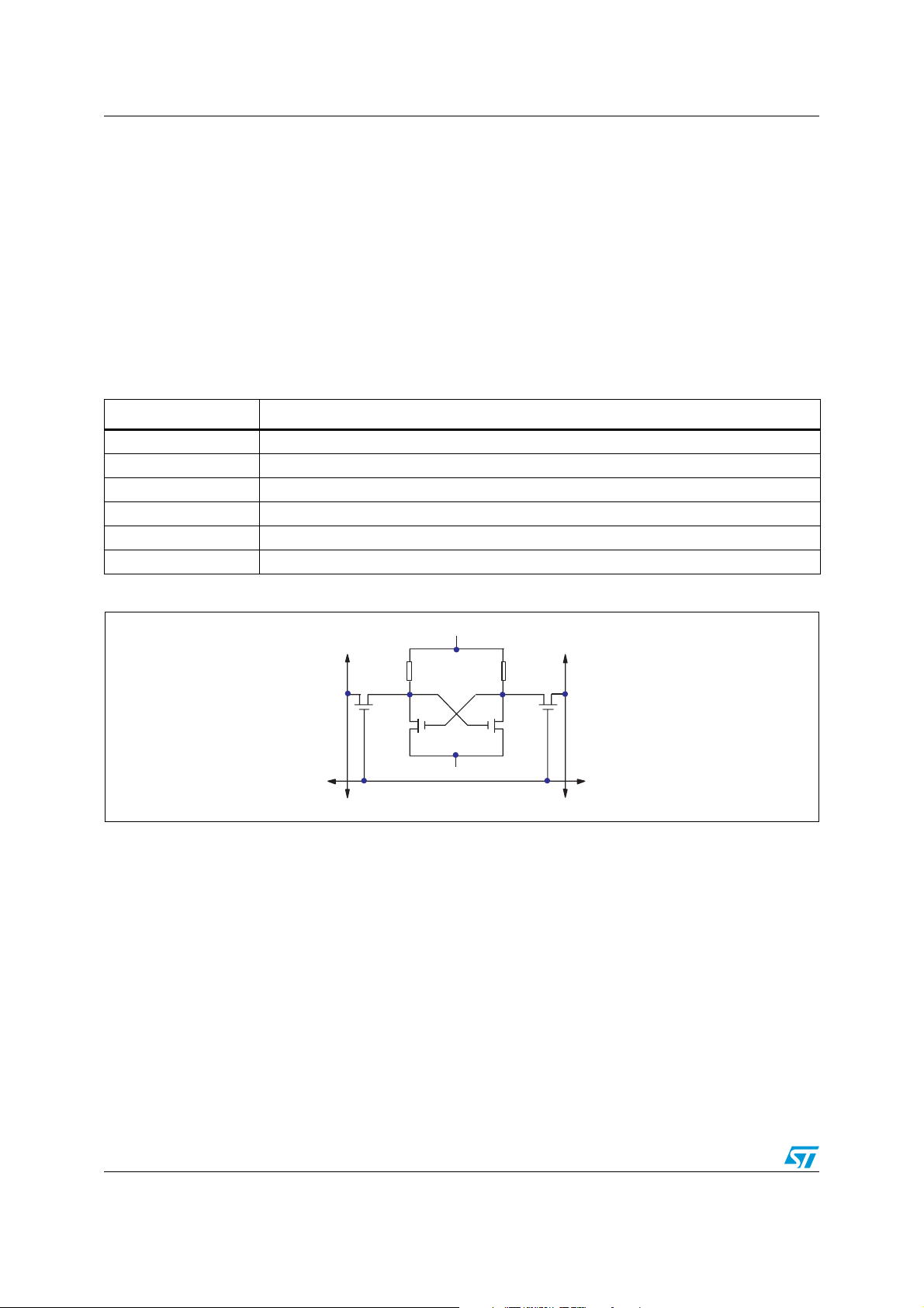
1 Process technology
The ZEROPOWER®, TIMEKEEPER®, supervisor, and serial RTC families consist of a
broad range of products that encompass various technologies. These products can be
divided into six categories, as shown in Ta bl e 1 . The SRAM array is generally based on a
6-transistor or 4-transistor cell, as indicated by the categories (6T and 4T). Figure 2
illustrates a one-bit storage cell from a 4-transistor SRAM cell.
The hybrid devices (also known as module devices) contain individually packaged analog
circuitry and SRAM. They are not covered in this document, except for the table of values for
typical battery lifetimes in Appendix A: Product data on page 25.
Table 1. ZEROPOWER and TIMEKEEPER
®
product categories
Category Devices
ZEROPOWER (4T cell) M48Z02, M48Z12, M48Z08, M48Z18, M48Z58/Y, M48Z35/Y/AV
ZEROPOWER Hybrid M48Z128/Y, M48Z129V, M48Z512A/AY, M48Z2M1V/Y
TIMEKEEPER (4T cell) M48T08/Y, M48T58/Y, M48T35/Y/AV, M48T37V/Y
TIMEKEEPER Hybrid M48T128Y, M48T129V, M48T512Y
Supervisors M40Z111/W, M40Z300W, M48T201V/Y
Serial RTCs (6T cell) M41T00/S, M41T11, M41T56, M41T81/S, M41T94, M41ST85W, M41ST87W
Figure 2. Four-transistor (4T) SRAM cell
SUPPLY VOLTAGE
POLY-LOAD
Q1
BIT-LINE
RESISTORS
Q3 Q4
GND
ROW SELECT
Q2
BIT-LINE
AI02457
The first devices, released in 1982, were based on a conventional 6T, full-CMOS, SRAM
design. These were specified for low-voltage data retention, and were built to stringent
manufacturing and test specifications. With data retention currents of less than 150 nA at
70 °C, these devices were designed to retain data in battery backup for at least 10 years
over the full commercial temperature range.
Newer devices have since been released. They use 4T, CMOS SRAM arrays. By using two
poly-R resistors in place of the pull-up transistors of full-CMOS design, the 4T cell is much
smaller than the 6T equivalent. Die size is dramatically reduced because the poly-R
resistors can be stacked on top of n-channel pull-down MOSFETs in the cell. This leads to a
net reduction in the device costs. Although the current drawn from the lithium cell is
increased, the devices have been specified to outlast the useful life of most equipment in
which they are used.
6/33 Doc ID 6395 Rev 4
Page 7
AN1012 Battery technology
2 Battery technology
STMicroelectronics uses both the BR1225 and the BR1632 lithium button cell batteries.
These have charge capacities of 48 mAh and 120 mAh, respectively. Their constituents
have non-toxic and non-corrosive characteristics, and are chemically and thermally stable
before, during, and after discharge. This makes these cells particularly attractive for use in
electrical components.
They contain a solid carbon cathode that is pressed into a tablet of predetermined weight
and height. The anode consists of high-purity lithium metal. The electrolyte is based on an
organic solvent instead of the corrosive alkaline or acidic solution found in most
conventional batteries. This greatly reduces the likelihood of internally-induced cell leakage,
and reduces the ill effects in cases of externally-induced cell leakage. The cell is then crimp-
sealed with a polypropylene grommet.
ST has conducted extensive tests on these cells, at temperatures up to 85 °C. Destructive
analysis was conducted (post-stress), in order to measure such factors as weight loss and
remaining charge capacity. The analysis determined that the cells were drying out, and that
the weight loss was due to electrolyte evaporation. Models were developed to predict the
nominal rate of electrolyte loss, and how this would be reduced by adding a second level of
encapsulation. This proprietary secondary seal encapsulation, adopted by ST, has been
found to provide up to a two-fold reduction of the electrolyte loss rate.
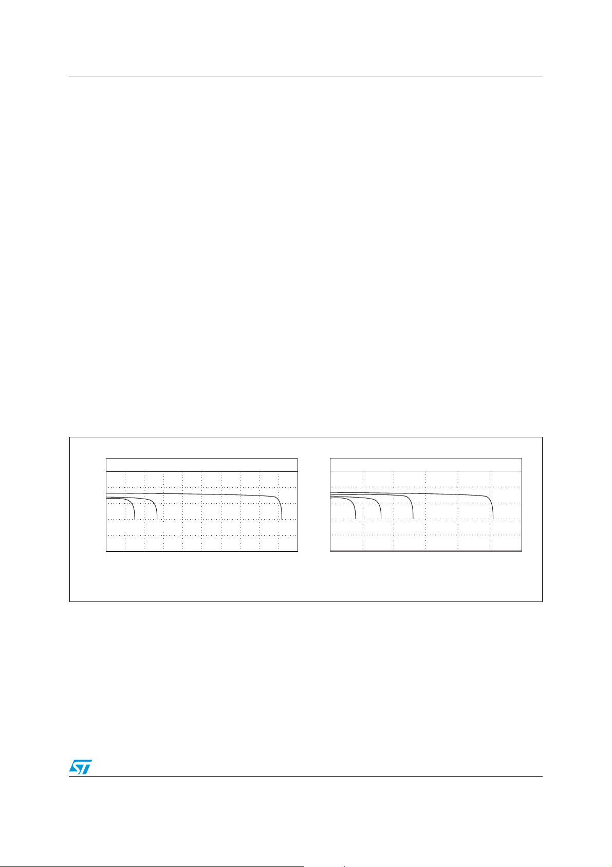
Both cells produce a nominal 2.9 V output with a flat discharge curve until the end of their
effective lives, and thus confirms that both are suitable for providing battery backup to low
leakage CMOS SRAMs (see Figure 3).
Figure 3. (A) BR1225 discharge rate and (B) BR1632 discharge rate
LOAD CHARACTERISTICS Temp: 20°C
3.5
3.0
2.5
2.0
Voltage (V)
15kΩ 30kΩ
1.5
1.0
0
200 400 600 1200 1600 1800
800 1000 1400 2000
Duration (Hrs.)
(A)
100kΩ
LOAD CHARACTERISTICS Temp: 20°C
3.5
3.0
2.5
2.0
Voltage (V)
15kΩ 30kΩ 50kΩ 100kΩ
1.5
1.0
1000 2000 3000 4000 5000 6000
0
Duration (Hrs.)
(B)
AI02519
Doc ID 6395 Rev 4 7/33
Page 8

Battery backup current - predicting data retention time AN1012
3 Battery backup current - predicting data retention
time
A ZEROPOWER®, TIMEKEEPER®, supervisor, or serial RTC device will reach the end of
its useful life for one of two reasons:
● Capacity consumption
It becomes discharged, having provided current to the SRAM (and to the oscillator in
the case of the TIMEKEEPER) in the battery backup mode.
● Storage life
The effects of aging will have rendered the cell inoperative before the stored charge
has been fully consumed by the application.
The two effects have very little influence on each other, allowing them to be treated as two
independent but simultaneous mechanisms. The data retention lifetime of the device is
determined by which ever failure mechanism occurs first.
3.1 Storage life
Storage life, resulting from electrolyte evaporation, is primarily a function of temperature.
Figure 4 illustrates the predicted storage life of the BR1225 battery versus temperature. The
results are derived from temperature-accelerated life test studies performed at
STMicroelectronics. For the purpose of testing, a cell failure is defined as the inability of a
cell, stabilized at 25 °C, to produce a 2.4 V closed-circuit voltage across a 250 kΩ load
resistor.
The two lines, SL
storage life. At 60 °C, for example, the SL
of failure 28 years into its life, and the SL
of failure at the 50 year mark. The SL
can be considered the worst case storage life for the cell. The SL
and SL
1%
, represent different failure rate distributions for the cell’s
50%
line indicates that the battery has a 1% chance
1%
line shows that the battery has a 50% chance
50%
line represents the practical onset of wear out, and
1%
line can be considered
50%
to be the normal, or average, life. As indicated by the curves in Figure 4 on page 9, storage
life does not become a limiting factor to overall battery life until temperatures in excess of
60 °C to 70 °C are involved.
As an approximation, SL
= 14270 x (0.91)T, and SL1% = 8107 x (0.91)T, when
50%
20 °C < T < 90 °C.
8/33 Doc ID 6395 Rev 4
Page 9
AN1012 Battery backup current - predicting data retention time
Figure 4. Predicted battery storage life versus temperature
50
40
30
SL
(AVERAGE)
20
SL
1%
10
8
6
5
4
STORAGE LIFE (Years)
3
2
1
20 30 40 50 60 70 80 90
TEMPERATURE (Degrees Celsius)
50%
AI01024b
3.2 Calculating storage life
Only the user can estimate predicted storage life in a given design because the ambient
temperature profile is dependent upon application-controlled variables. As long as the
ambient temperature is held reasonably constant, the expected storage life can be read
directly from Figure 4 on page 9. If the battery spends an appreciable amount of time at a
variety of temperatures, the following formula can be used to estimate predicted storage life:
t
⎛⎞
1
-----
×
⎜⎟
T
⎝⎠
t
⎛⎞
1
2
-----
---------SL
×
+++
⎜⎟
T
⎝⎠
1
1
---------SL
t
⎛⎞
n
-----
…
×
⎜⎟
T
2
⎝⎠
---------SL
1–
1
n
where,
● t
/T is the relative proportion (of the total time) during which the device is at ambient
i
temperature TA
● SL
● T is the total time = t
is the storage life at ambient temperature TAi as illustrated in Figure 4; and
i
;
i
1
+ t2 + ... + tn.
For example, consider a battery exposed to temperatures of up to 90 °C for 600 hrs/yr, and
temperatures of 60 °C or less for the remaining 8160 hrs/yr. Reading predicted t
values
1%
from Figure 4,
● SL
● SL
● T is 8760 hrs/yr;
● t
● t
is about 1.8 yrs;
1
is about 28 yrs;
2
is 600 hrs/yr; and
1
is 8160 hrs/yr.
2
The predicted storage life evaluates to:
600
1
⎛⎞
---------------
⎝⎠
8760
⎛⎞
---------
+
×
⎝⎠
1.8
8160
---------------
8760
1
------
×
28
1–
This predicts that the storage life, in this particular case, is at least 14 years. This is,
therefore, better than the normally accepted life time of 10 years.
Doc ID 6395 Rev 4 9/33
Page 10

Battery backup current - predicting data retention time AN1012
3.3 Capacity consumption
When VCC is being held by the external power supply within its specified range, the current
drawn from the battery is zero. When V
(V
), the device goes into battery backup mode and draws all of its current from the
SO
battery.
falls below the battery backup switchover voltage
CC
The V
duty cycle represents the proportion of time, expressed as a percentage, that the
CC
device is supplied with power from the external supply, and therefore not drawing current
from the battery.
In its battery backup mode, the array of SRAM cells can be characterized by its data
retention (I
) current, caused primarily by the current through the Poly-R load resistors
CCDR
in the 4T technology, as well as also by junction leakage, sub-threshold current, and gate-tosubstrate leakage. The total current is referred to as I
backup mode). For ZEROPOWER
®
devices, this is the sum of leakage currents plus the
current necessary to maintain the SRAM array. For TIMEKEEPER
the array current (including leakage) and the clock current:
I
BAT
= I
ARRAY
+ I
Many factors need to be taken into account when calculating the I
process parameters, working temperature, and the V
3.4 Calculating capacity consumption
Capacity consumption is simply calculated by:
-----------------------------------------------------------------------------------------------------
8760 1 V
where:
● Battery capacity is measured in ampere-hours;
● 8760 is the constant for the number of hours there are in a year;
● V
● I
duty cycle is measured as a percentage; and
CC
is measured in amperes.
BAT
For the M48T35Y, a 32K x 8 TIMEKEEPER
BR12SH1 battery, the typical battery current is approximately 2666 nA at 70 °C.
BatteryCapacity
×
CC
DutyCycle 100⁄–()I×
®
device with a 0.048 Ah (48 mAh) M4T28-
(the current drawn during battery
BAT
®
devices, it is the sum of
CLOCK
current, including
duty cycle.
CC
BAT
BAT
So, if the V
duty cycle is 50%, the predicted capacity life is:
CC
------------------------------------------------------------ -
8760 0.5 2666 10
0.048
and therefore is about 4.11 years at 70 °C.
10/33 Doc ID 6395 Rev 4
9–
×××
Page 11

AN1012 4T cell devices
4 4T cell devices
In moving to the newer process technologies (e.g., M48Z58 (8K x 8) device),
STMicroelectronics has chosen to reduce the active current as well as decrease the die
size. The STMicroelectronics HCMOS4PZ process is a 0.6 μm, double-level metal process.
In the standard SRAM memory cell, 6 transistors are formed into a pair of cross-coupled
inverters. In the 4T memory cell, the top two p-channel devices are replaced by poly-silicon
load resistors (poly-R). This combination allows for significant die size reduction because
the poly-R structures can be stacked on top of the active n-channel devices.
There is always at least one direct path constantly leaking current to ground in each cell
because of the poly-R structures in each SRAM cell. However, the value of the resistor is
extremely high (about 3TΩ at 25 °C), so at a cell voltage of 3 V, this leads to a leakage
current of 1 pA. Multiplying by the number of cells within the array, the array standby current
can be calculated (i.e. 65.5 nA for a 65536-cell array).
The poly-R structure values are dependent on temperature, so the entire array current is
very strongly temperature-dependent. Appendix B: ZEROPOWER products on page 26
shows the expected battery lifetime of an M48Z58 device versus working temperature with a
V
duty cycle of 0%.
CC
The original specification was an expected lifetime of greater than 10 years at 25 °C but, in
fact, this target is typically achieved even at 70 °C. By reducing the temperature, the
expected lifetime rises to greater than 20 years (i.e., when the device is operated at 50 °C).
This change is defined entirely by the temperature sensitivity of the poly-R structures within
each SRAM cell.
The M48Z35 also employs the STMicroelectronics HCMOS4PZ process, 4T SRAM cell
technology. Appendix B shows the expected battery lifetime of an M48Z35 device versus
working temperature with a V
lifetime is typically greater than 20 years when operated at 30 °C with no external V
duty cycle of 0%. From this we can see that expected
CC
CC
applied, and falls to approximately 2.6 years for continuous battery backup at 70 °C. This is
to be expected, due to the increased current consumption inherent in the 4T SRAM cell
architecture. It should be noted that this data is based on usage of the SNAPHAT
®
product
which includes a 48 mAh battery.
Doc ID 6395 Rev 4 11/33
Page 12

TIMEKEEPER products AN1012
5 TIMEKEEPER products
TIMEKEEPER® products are very similar in construction and operation to ZEROPOWER®
products. However, they must be evaluated separately. The current drawn is highly
dependent not only on the temperature, but also on whether the oscillator is active. The
main components of TIMEKEEPER devices are (see Figure 5):
● a CMOS RAM array;
● voltage sense and switching circuitry;
● an analog oscillator and clock chain;
● a lithium power cell; and
● a high-accuracy quartz crystal.
Figure 5. Block diagram of a TIMEKEEPER
IRQ/FT
OSCILLATOR AND
CLOCK CHAIN
32,768 Hz
CRYSTAL
POWER
LITHIUM
CELL
VOLTAGE SENSE
AND
SWITCHING
CIRCUITRY
CC
RSTV
V
PFD
®
device
16 x 8 BiPORT
SRAM ARRAY
8176 x 8
SRAM ARRAY
V
SS
A0-A12
DQ0-DQ7
E
W
G
AI01383D
12/33 Doc ID 6395 Rev 4
Page 13

AN1012 TIMEKEEPER products
5.1 TIMEKEEPER® register map
Ta bl e 2 shows a typical register map for the seconds, minutes, hours, date, day, month, and
year fields. This information is stored in Binary Coded Decimal (BCD) format. These basic
functions are available on all TIMEKEEPER devices. Additional features (e.g., watchdog
timer, alarms, battery low flag, and a wake-up function) have additional registers allocated to
them (such as those shown for the M48T37V/Y in Ta bl e 2 ). The TIMEKEEPER register
locations are constructed from BiPORT™ memory cells which allow data access from two
sides. The on-chip system clock connects to one side (the system side) and the user data is
output to connections on the other (the user’s side). At one-second intervals, clock pulses
are generated by the oscillator and clock chain structure. The system side updates the new
time in the TIMEKEEPER registers. Each TIMEKEEPER register location (e.g. minutes,
hours, day) is then updated as necessary. When the user wants to write a new time, the “W”
bit (the Write bit) of the control register is reset, causing the BiPORT cells to upload the new
system time. The user accesses the TIMEKEEPER and array data by executing standard
READ/WRITE cycles.
The oscillator and clock chain structure consists of a mixture of analog and digital circuitry,
and account for the majority of the I
currents drawn as a function of technology and working temperature.
Table 2. Typical TIMEKEEPER (M48T37V/Y) register map
Address
D7 D6 D5 D4 D3 D2 D1 D0
current. Ta bl e 3 gives conservative estimates of the
BAT
Data
Function
Range
(in BCD
format)
7FFFh 10 Years Year Year 00-99
7FFEh 0 0 0 10M Month Month 01-12
7FFDh 0 0 10 Date Date Date 01-31
7FFCh 0 FT 0 0 0 Day Day 01-7
7FFBh 0 0 10 Hours Hours Hours 00-23
7FFAh 0 10 Minutes 10 Minutes Minute 00-59
7FF9h ST 10 Seconds Seconds Second 00-59
7FF8h W R S Calibration Control
7FF7h WDS BMB4 BMB3 BMB2 BMB1 BMB0 RB1 RB0 Watch
7FF6h AFE 0 ABE 0 0 0 0 0 Interrupt
7FF5h RPT4 0 AI 10 Date Alarm Date A Date 01-31
7FF4h RPT3 0 AI 10 Hour Alarm Hour A Hour 00-23
7FF3h RPT2 Alarm 10 Minutes Alarm Minutes A Minute 00-59
7FF2h RPT1 Alarm 10 Seconds Alarm Seconds A Second 00-59
7FF1h 1000 Years 100 Years Century 00-99
7FF0h WDF AF 0 BL Z Z Z Z Flags
Table 3. Typical I
current for TIMEKEEPER devices
BAT
Typical at 20°C Typical at 70°C
Capacity Technology Array Clock Array Clock
64 Kbit 4T Cell 40 nA 497 nA 511 nA 619 nA
Doc ID 6395 Rev 4 13/33
Page 14

TIMEKEEPER products AN1012
5.2 TIMEKEEPER® evolution
TIMEKEEPER products have seen a continuous evolutionary cycle since their initial market
introduction in the 1990s.
5.2.1 M48T02 and M48T12
The first TIMEKEEPER products released were the MK48T02 and MK48T12 which offered
2K x 8 RAM and employed the STMicroelectronics 2.0 μm Spectrum™ CMOS technology.
When released, these products included a BR1225 lithium cell with a specified 39 mAh
capacity. This combination offered the user approximately 3.5 years of continuous battery
backup life. Since that time, the devices have been moved to the 4T cell technology
(HCMOS4PZ) and a CAPHAT™ package revision which includes a larger capacity lithium
cell (120 mAh BR1632) capacity, and new part numbers (M48T02/12). These changes
increased the expected battery life to 19 years at 60°C.
Figure 6 shows expected battery lifetime versus temperature with 100% battery backup. The
data shows that by operating the devices at various temperatures, designers can expect a
battery life approaching 20 years under most conditions.
Figure 6. M48T02/12 data retention lifetime vs. temperature (120 mAh, 100% battery
backup)
14/33 Doc ID 6395 Rev 4
Page 15

AN1012 TIMEKEEPER products
5.2.2 M48T08 and M48T18
The next TIMEKEEPER® to be released was the MK48T08/18 family, which has an 8K x 8
SRAM array. By using the more advanced 1.2 μm HCMOS3 process and refining the onboard oscillator, STMicroelectronics was able to offer a nearly three-fold increase in battery
lifetime, even though the array size had increased by a factor of four. This product was later
converted to the 0.6 µm, double-level metal HCMOS4PZ process for 4T SRAM cells. The
battery was then upgraded to 120 mAh for the CAPHAT™ package revision (part numbers
M48T08/18), which provides a battery life of at least 10 years across the commercial
temperature range (0 °C to 70 °C, see Figure 7).
In the M48T08/18 datasheet, the battery lifetime (t
specified as 10 years or greater across the commercial temperature range (for a 0% V
, data retention time) has been
DR
CC
duty cycle).
Figure 7. M48T08/18 data retention lifetime vs. temperature (120 mAh, 100% battery
backup)
Doc ID 6395 Rev 4 15/33
Page 16

TIMEKEEPER products AN1012
5.2.3 M48T58
The next TIMEKEEPER® product was the M48T58 which is fabricated on the 0.6 µm,
double-level metal HCMOS4PZ process for 4T SRAM cells.
Table 13 on page 28, Appendix C: TIMEKEEPER
Figure 9 on page 16 show the extent to which the data retention of these devices is more
dependent on temperature. Higher temperatures cause lower resistor values (and therefore,
higher currents) because of the negative temperature coefficient of the poly-R resistors.
Data retention lifetimes typically range from 8.6 years (at 30 °C) for devices in the
CAPHAT™ package, with a 48 mAh battery (see Figure 8), and up to 20 years (and more)
for the SNAPHAT package with a 120 mAh BR1632 battery (see Figure 9). As always,
several factors affect battery lifetime, including the V
Figure 8. M48T58 data retention lifetime vs. temperature (48 mAh, 100% battery
backup)
®
products on page 28, Figure 8, and
duty cycle and temperature.
CC
Figure 9. M48T58 data retention lifetime vs. temperature (120 mAh, 100% battery
backup)
16/33 Doc ID 6395 Rev 4
Page 17

AN1012 TIMEKEEPER products
5.2.4 M48T35 and M48T37V/Y
The M48T35 and M48T37V/Y families use the same technology as the M48T58 device, but
with a 32K x 8 SRAM array. Figure 10 and Figure 11 show the expected battery lifetime
versus temperature. The expected battery lifetime (at 30 °C with no periods of valid V
typically 6.8 years (this assumes that a 48 mAh battery is used, see Figure 10). Devices in
the larger M4T32-BR12SH SNAPHAT
®
package have a data retention lifetime of greater
than twice this (almost 17 years, see Figure 11).
Figure 10. M48T35/37V/37Y data retention lifetime vs. temperature (48 mAh, 100%
battery backup)
CC
) is
Figure 11. M48T35/37V/37Y data retention lifetime vs. temperature (120 mAh, 100%
battery backup)
Doc ID 6395 Rev 4 17/33
Page 18

TIMEKEEPER products AN1012
If data retention lifetimes greater than those shown are required, the user is advised to
choose the version of the device in a SNAPHAT
®
package. Then, as the battery starts to
reach the end of its useful life, it is possible to remove the SNAPHAT top containing the
nearly expended cell and replace it with a fresh SNAPHAT top. No data will be lost during
the process, provided that the board remains powered up during the operation (although
some time will be lost due to the momentary removal of the 32 kHz crystal). Ta bl e 4 shows
which SNAPHAT top part numbers are available.
Table 4. SNAPHAT part numbers
Part Number Description Package
M4Z28-BR00SH Li Battery (48mAh) for ZEROPOWER products and SUPERVISORS SNAPHAT
M4Z32-BR00SH Li Battery (120mAh) for ZEROPOWER products and SUPERVISORS SNAPHAT
M4T28-BR12SH Li Battery (48mAh) for TIMEKEEPER products and SUPERVISORS SNAPHAT
M4T32-BR12SH Li Battery (120mAh) for TIMEKEEPER products and SUPERVISORS SNAPHAT
18/33 Doc ID 6395 Rev 4
Page 19

AN1012 Supervisor products
6 Supervisor products
STMicroelectronics also has a family of ZEROPOWER® and TIMEKEEPER® supervisor
devices. Supervisors are self-contained units that allow standard low-power SRAMs to be
turned into non-volatile memory devices. They monitor and provide V
more external SRAMs the same way ZEROPOWER and TIMEKEEPER products do. They
use a precision voltage reference and comparator to monitor the V
tolerance.
input for one or
CC
input for going out-of-
CC
When V
becomes invalid, the supervisor’s conditioned chip-enable outputs (E
CC
CON
) are
forced to their “inactive” state, thereby putting each external SRAM into its own write-protect
state. During the power failure, the supervisor provides the power for the SRAM from the
lithium cell within its SNAPHAT top. The supervisor switches the power source back to the
V
supply as soon as the voltage returns to specified levels.
CC
Doc ID 6395 Rev 4 19/33
Page 20

Choosing SRAM AN1012
7 Choosing SRAM
Most low power SRAMs on the market today can be used with both ZEROPOWER® and
TIMEKEEPER
®
supervisors, although there are some issues that need addressing before
finally choosing which SRAM to use.
● The chip enable input, when taken inactive, must disable all the other inputs to the
SRAM. This allows inputs to the external SRAMs to be treated as “Don’t care” once
V
falls below V
CC
● The SRAM should guarantee data retention when working at V
● The chip-enable access time must be sufficient to meet the system needs, taking into
PFD
(min).
= 2.0 volts.
CC
account propagation delays on chip enable and output enable.
Most SRAMs specify a data retention current (I
) at 3.0 V. Manufacturers generally
CCDR
specify a typical condition for room temperature along with a worst case condition (generally
at elevated temperatures). The system level requirements will determine the choice of which
value to use. The data retention current value of the SRAMs can then be added to the I
value of the supervisor to determine the total current requirements for data retention. The
available battery capacity for the SNAPHAT
®
of your choice can then be divided by this
BAT
current to determine the data retention period (see Section 3.3: Capacity consumption on
page 10).
For example, the M48T201V/Y has an I
The M40Z300W has an I
value of 5 nA at 25 °C, and 100 nA at 70 °C. Ta bl e 5 indicates
BAT
value of 575 nA at 25 °C, and 800 nA at 70 °C.
BAT
typical data retention lifetimes for the M40Z300W ZEROPOWER supervisor when it is used
with a number of commercially available 1 Mbit and 4 Mbit SRAMs. Table6 on page21
shows the same kind of information for the M48T201V/Y TIMEKEEPER supervisors.
Table 5. M40Z300W (120mAh SNAPHAT) data retention life vs. SRAM type
I
(SRAM) (nA) I
Size
(Mbit)
Hynix
1
Renesas
4 Renesas
8
1. According to the respective manufacturer’s datasheets at the time of writing.
2. 3 V device
Renesas HM62V8100LTTI-5SL 500 10000 505 10100 > 20 1.4
Samsung K6X8008T2B-UF5500 N/A 15000 N/A 15100 N/A 0.9
Product
HY628100BLLT1-55 1000 10000 1005 10100 13.6 1.4
HY62V8100BLLT1-70
M5M51008DVP-55H 500 10000 505 10100 > 20 1.4
M5M5V108DVP-70H
R1LP0408CSB-5SC 800 8000 805 8100 17.0 1.7
R1LV0408CSB-5SC
(2)
(2)
(2)
BAT
25°C 70°C 25°C 70°C 25°C 70°C
1000 10000 1005 10100 13.6 1.4
1000 10000 1005 10100 13.6 1.4
500 8000 805 8100 > 20 1.7
(Total) (nA)
BAT
Lifetime in
(1)
years
20/33 Doc ID 6395 Rev 4
Page 21

AN1012 Choosing SRAM
Table 6. M48T201V/Y (120 mAh SNAPHAT) data retention life vs. SRAM type
Size
(Mbit)
Product
I
(SRAM) (nA) I
BAT
(Total) (nA) Lifetime in years
BAT
25°C 70°C 25°C 70°C 25°C 70°C
(1)
Hynix
1
Renesas
4
Renesas
Renesas HM62V8100LTTI-5SL 500 10000 1075 10800 12.7 1.3
8
HY628100BLLT1-55 1000 10000 1075 10800 8.7 1.3
HY62V8100BLLT1-70
(2)
1000 10000 1075 10800 8.7 1.3
M5M51008DVP-55H 500 10000 1075 10800 12.7 1.3
M5M5V108DVP-70H
(2)
1000 10000 1575 10800 8.7 1.3
R1LP0408CSB-5SC 800 8000 1375 8800 10.0 1.6
R1LV0408CSB-5SC
(2)
500 8000 1075 8800 12.7 1.6
Samsung K6X8008T2B-UF5500 N/A 15000 N/A 15800 N/A 0.9
1. According to the respective manufacturer’s datasheets at the time of writing.
2. 3 V device
Doc ID 6395 Rev 4 21/33
Page 22

Industrial temperature devices AN1012
8 Industrial temperature devices
Due to ever increasing requirements for portability and operation under extreme
environmental conditions, STMicroelectronics offers industrial temperature versions
(–40°C to +85°C) of our serial RTC devices. This expanded operating range allows these
products to perform under more extreme temperatures for applications such as:
● cell phone base stations;
● traffic control;
● portable equipment;
● land, water, and aircraft instrumentation; and
● industrial control equipment.
These products are indicated by the digit ‘6’ at the end of the sales-type. The industrial
temperature TIMEKEEPER
data retention lifetimes are listed in Appendix B: ZEROPOWER products on page 26 and
Appendix C: TIMEKEEPER
®
SNAPHAT® top is also designated by the suffix “6.” Predicted
®
products on page 28.
22/33 Doc ID 6395 Rev 4
Page 23

AN1012 U.L. recognition and recycling
9 U.L. recognition and recycling
While providing innovative, leading edge products, STMicroelectronics remains committed
to safety, including its products, its customers, and the environment. Each device contains
reverse-charge protection circuitry, and uses safe lithium mono-fluoride batteries. All
ZEROPOWER
Underwriter’s Laboratory under file number E89556, and are compliant to the LL-94-VO
flammability rating.
The unique SNAPHAT packaging consists of a 330 mil SOIC device and a separate, “snapon” SNAPHAT, which includes both the lithium power cell, and in the case of TIMEKEEPER
product, a high accuracy crystal. The SNAPHAT is removable and can be replaced,
providing the added benefit of proper disposal or recycling that has not been available
before with NVRAMs. Various companies offer recycling and safe disposal of scrap lithium
cells.
®
, TIMEKEEPER, supervisor, and serial RTC components are recognized by
Doc ID 6395 Rev 4 23/33
Page 24

Summary AN1012
10 Summary
Battery life and data retention for ZEROPOWER® and TIMEKEEPER® products are
primarily functions of two factors:
● Capacity consumption, and
● Storage life of the lithium button cell battery.
Due to the fact that storage life (caused by electrolyte evaporation) has little effect at
temperatures below 60 °C, the data retention of most applications will be dependent upon
the I
simple calculation (see Section 3.4: Calculating capacity consumption on page 10) to be
used to determine the lifetime.
All ST ZEROPOWER products are able to offer at least a 10 year data retention life, typically
at 40 °C. This may be increased by reducing the temperature, increasing the V
or in the case of the surface mount SNAPHAT
SNAPHAT top.
For the TIMEKEEPER family, battery lifetimes are also affected by the percentage of time
the oscillator is in operation. Commercial devices fabricated in 4T technologies provide
7 years of continuous operation at 20 °C using the 48 mAh M4T28-BR12SH SNAPHAT top,
and typically greater than 15 years with the 120 mAh M4T32-BR12SH SNAPHAT top.
of the SRAM being backed-up, as well as the VCC duty cycle. This allows a fairly
CCDR
®
products, using the larger 120 mAh
CC
duty cycle,
The ZEROPOWER and TIMEKEEPER supervisor families allow the user to purchase
commodity SRAMs at the best available market price. However, overall data retention life
will be determined by the I
of the SRAM selected.
CCDR
24/33 Doc ID 6395 Rev 4
Page 25

AN1012 Product data
Appendix A Product data
Note: The symbol “>>” means, “... much greater than...”
®
Table 7. Data for ZEROPOWER
Device Process technology
M48Z02/12 0.6 μm, HCMOS4PZ 4T n/a BR1225 9 10
M48Z08/18 0.6 μm, HCMOS4PZ 4T BR1225 BR1225 37 10
M48Z35/Y/AV 0.6 μm, HCMOS4PZ 4T BR1225 BR1225 148 10
M48Z58/Y 0.6 μm, HCMOS4PZ 4T BR1225 BR1225 37 10
M48T02/12 0.6 μm, HCMOS4PZ 4T N/A BR1632 506 10
M48T08/18 0.6 μm, HCMOS4PZ 4T BR1225 BR1632 535 10
M48T35/Y/AV 0.6 μm, HCMOS4PZ 4T BR1225 BR1632 646 7/10
M48T37Y 0.6 μm, HCMOS4PZ 4T BR1225 N/A 646 7
M48T58/Y 0.6 μm, HCMOS4PZ 4T BR1225 BR1225 535 7
1. The data retention lifetime can be significantly increased by using the SNAPHAT (ZEROPOWER or TIMEKEEPER, as
appropriate) with the higher capacity BR1632 battery.
2. The larger capacity BR1632 (120 mAh) battery is also available in the SNAPHAT package.
and TIMEKEEPER® devices
Battery type
SRAM
Cell
SNAPHAT
(2)
CAPHAT
I
BAT
(T = 20°C)
(nA)
Typical data
retention
lifetime
(1)
(years)
Table 8. Data from hybrid/module devices (V
Specification
Device
M48Z128/Y 10 >> 20 > 20 2.3
M48Z129V 10 >> 20 > 20 2.3
M48Z512A/AV/AY 10 >> 20 > 20 6.0
M48Z2M1V/Y 10 > 20 > 20 3.1
M48T128Y 10 > 20 16.6 2.0
M48T129V/Y 10 > 20 16.6 2.0
M48T512Y 10 > 20 19.4 4.8
at T = 25°C
(years)
duty cycle = 0%)
CC
Experimental conditions (years)
0°C 25°C 70°C
Note: These devices are not recommended for new design. Please contact local ST sales office
for availability.
Doc ID 6395 Rev 4 25/33
Page 26

ZEROPOWER products AN1012
Appendix B ZEROPOWER products
The tables in this appendix use the terms “typical” and “worst case” to indicate the “mean
value at the given temperature” and “mean value plus maximum expected deviation at the
given temperature.”
Note: The symbol “>>” means, “... much greater than...”
Table 9. Data from M48Z02/12 devices (available only in CAPHAT™ - BR1225,
48 mAh)
V
duty cycle = 0%
Tem peratu r e
(°C)
0 >> 20 >> 20 >> 20
10 >> 20 >> 20 >> 20
20 >> 20 >> 20 >> 20
25 >> 20 >> 20 >> 20
30 >> 20 >> 20 >> 20
40 >> 20 >> 20 >> 20
50 >> 20 >> 20 >> 20
60 > 20 > 20 > 20
70 11.0 11.0 11.0
Typical (years) Worst case (years)
CC
duty cycle = 100%,
V
CC
shelf life (years)
Table 10. Data from M48Z08/18, M48Z58, and M48Z58Y devices
CAPHAT or SNAPHAT
(BR1225, 48 mAh)
Temperature
(°C)
Typical
(years)
0 >> 20 >> 20 >> 20 >> 20 >> 20
10 >> 20 >> 20 >> 20 >> 20 >> 20
20 >> 20 >> 20 >> 20 >> 20 >> 20
25 >> 20 >> 20 >> 20 >> 20 >> 20
30 >> 20 >> 20 >> 20 >> 20 >> 20
40 >> 20 > 20 >> 20 >> 20 >> 20
50 > 20 16.4 >> 20 >> 20 >> 20
60 19.7 10.1 > 20 >20 > 20
70 11.0 5.8 11.0 11.0 11.0
VCC duty cycle = 0%
Worst case
(years)
SNAPHAT
(BR1632, 120 mAh)
Typical
(years)
Worst case
(years)
V
duty cycle = 100%,
CC
shelf life (years)
26/33 Doc ID 6395 Rev 4
Page 27

AN1012 ZEROPOWER products
Table 11. Data from M48Z35/Y/AV devices
CAPHAT or SNAPHAT
(BR1225, 48 mAh)
Tem peratu r e
(°C)
Typical
(years)
V
duty cycle = 0%
CC
Worst case
(years)
0 >> 20 >> 20 >> 20 >> 20 >> 20
10 >> 20 > 20 >> 20 >> 20 >> 20
20 >> 20 > 20 >> 20 >> 20 >> 20
25 > 20 17.2 >> 20 >> 20 >> 20
30 > 20 12.9 >> 20 > 20 >> 20
40 14.2 7.5 > 20 18.6 >> 20
50 7.4 3.8 18.4 9.5 >> 20
60 4.5 2.5 11.3 6.2 > 20
70 2.6 1.4 6.5 3.5 11.0
SNAPHAT
(BR1632, 120 mAh)
Typical
(years)
Worst case
(years)
V
duty cycle = 100%,
CC
shelf life (years)
Doc ID 6395 Rev 4 27/33
Page 28

TIMEKEEPER® products AN1012
Appendix C TIMEKEEPER® products
Table 12. Data from M48T02/12 devices (available only in CAPHAT™ - BR1632,
120 mAh)
V
duty cycle = 0%
Tem peratu r e
(°C)
0 > 20 > 20 >> 20
10 > 20 > 20 >> 20
20 > 20 > 20 >> 20
25 > 20 > 20 >> 20
30 > 20 > 20 >> 20
40 > 20 > 20 >> 20
50 > 20 18.5 >> 20
60 19.0 17.0 > 20
70 11.0 11.0 11.0
Typical (years) Worst case (years)
Table 13. Data from M48T08/Y/18 and M48T58/Y devices
CAPHAT or SNAPHAT
(BR1225, 48 mAh)
Temperature
(°C)
Typical
(years)
CC
CAPHAT
(BR1632, 120 mAh)
VCC duty cycle = 0%
Worst case
(years)
Typica l
(years)
(1)
or SNAPHAT
Worst case
(years)
duty cycle = 100%,
V
CC
shelf life (years)
VCC duty cycle = 100%,
shelf life (years)
0 11.0 10.0 > 20 > 20 >> 20
10 10.1 9.2 > 20 > 20 >> 20
20 9.4 8.5 > 20 > 20 >> 20
25 9.0 8.1 > 20 > 20 >> 20
30 8.6 7.6 > 20 19.0 >> 20
40 7.9 6.8 19.7 16.9 >> 20
50 6.9 5.6 17.1 13.9 >> 20
60 5.9 4.5 14.8 11.3 > 20
70 4.8 3.4 11.0 8.4 11.0
1. Only available in M48T08 and M48T18 CAPHAT™.
28/33 Doc ID 6395 Rev 4
Page 29

AN1012 TIMEKEEPER® products
Table 14. Data from M48T35/Y/AV and M48T37V/Y devices
SNAPHAT
(BR1225, 48 mAh)
Temperature
(°C)
Typica l
(years)
V
duty cycle = 0%
CC
Worst case
(years)
0 10.4 9.0 > 20 > 20 >> 20
10 9.0 7.6 > 20 19.1 >> 20
20 8.1 6.7 > 20 16.6 >> 20
25 7.4 6.0 18.6 14.9 >> 20
30 6.8 5.3 16.9 13.2 >> 20
40 5.5 4.0 13.8 10.0 >> 20
50 4.0 2.6 10.0 6.6 >> 20
60 2.9 1.9 7.4 4.8 > 20
70 2.0 1.2 5.0 3.0 11.0
CAPHAT or SNAPHAT
(BR1632, 120 mAh)
Typical
(years)
Worst case
(years)
V
duty cycle = 100%,
CC
shelf life (years)
Doc ID 6395 Rev 4 29/33
Page 30

Serial RTC products AN1012
Appendix D Serial RTC products
Table 15. Data from M41T56/94, M41ST85W, M41ST87W/Y, and M41ST95W ind.
temp. (MH6) devices
SNAPHAT (BR1632, 120 mAh)
Temperature
(°C)
–40 > 20 >> 20
–30 > 20 >> 20
–20 > 20 >> 20
–10 > 20 >> 20
0> 20 >> 20
10 > 20 >> 20
20 > 20 >> 20
25 > 20 >> 20
30 > 20 >> 20
40 > 20 >> 20
50 > 20 >> 20
60 > 20 > 20
70 11.0 11.0
80 4.3 4.3
85 2.7 2.7
VCC duty cycle = 0%
Typical (years)
V
duty cycle = 100%,
CC
shelf life (years)
30/33 Doc ID 6395 Rev 4
Page 31

AN1012 Serial RTC products
Table 16. Data from M41T00/S, M41T11, and M41T81/S industrial temperature (MH6)
devices
SNAPHAT (BR1632, 120 mAh)
Tem peratu r e
(°C)
VCC duty cycle = 0%
Typical (years)
–40 > 20 >> 20
–30 > 20 >> 20
–20 > 20 >> 20
–10 > 20 >> 20
0 > 20 >> 20
10 > 20 >> 20
20 > 20 >> 20
25 > 20 >> 20
30 > 20 >> 20
40 > 20 >> 20
50 > 20 >> 20
60 > 20 > 20
70 11.0 11.0
80 4.3 4.3
85 2.7 2.7
VCC duty cycle = 100%,
shelf life (years)
Doc ID 6395 Rev 4 31/33
Page 32

Revision history AN1012
11 Revision history
Table 17. Document revision history
Date Revision Changes
13-Oct-1998 0.0 Document written
14-Dec-1998 1.0 1st edition of ZEROPOWER and TIMEKEEPER application note book
07-Mar-2000 1.1
25-Apr-2000 1.2 Controllers renamed as supervisors
26-Jun-2000 1.3 M48T35 typ data retention lifetime changed to 7/10 years (Tab-7 on p15)
08-May-2001 2.0
15-May-2001 2.1 Change trend colors to black (Figure 6, 7, 8, 10)
31-May-2005 3.0
15-Sep-2011 4 Product updates; minor textual updates; revised document presentation.
Data changed from that of 49 mAh and 130 mAh batteries to that of
48 mAh and 120 mAh batteries
Reformatted, text, graphics, values updated (Figure 6, 7, 8, 10; Tab le 3 ,
5, 6, 7, 15, 13, 14, 16, 17)
Update information (Figure 1, 6, 7, 8, 9, 10; Ta b l e 1 , 3, 5, 6, 7, 8, 9, 11,
12, 13, 14, 15, 16)
32/33 Doc ID 6395 Rev 4
Page 33

AN1012
Please Read Carefully:
Information in this document is provided solely in connection with ST products. STMicroelectronics NV and its subsidiaries (“ST”) reserve the
right to make changes, corrections, modifications or improvements, to this document, and the products and services described herein at any
time, without notice.
All ST products are sold pursuant to ST’s terms and conditions of sale.
Purchasers are solely responsible for the choice, selection and use of the ST products and services described herein, and ST assumes no
liability whatsoever relating to the choice, selection or use of the ST products and services described herein.
No license, express or implied, by estoppel or otherwise, to any intellectual property rights is granted under this document. If any part of this
document refers to any third party products or services it shall not be deemed a license grant by ST for the use of such third party products
or services, or any intellectual property contained therein or considered as a warranty covering the use in any manner whatsoever of such
third party products or services or any intellectual property contained therein.
UNLESS OTHERWISE SET FORTH IN ST’S TERMS AND CONDITIONS OF SALE ST DISCLAIMS ANY EXPRESS OR IMPLIED
WARRANTY WITH RESPECT TO THE USE AND/OR SALE OF ST PRODUCTS INCLUDING WITHOUT LIMITATION IMPLIED
WARRANTIES OF MERCHANTABILITY, FITNESS FOR A PARTICULAR PURPOSE (AND THEIR EQUIVALENTS UNDER THE LAWS
OF ANY JURISDICTION), OR INFRINGEMENT OF ANY PATENT, COPYRIGHT OR OTHER INTELLECTUAL PROPERTY RIGHT.
UNLESS EXPRESSLY APPROVED IN WRITING BY TWO AUTHORIZED ST REPRESENTATIVES, ST PRODUCTS ARE NOT
RECOMMENDED, AUTHORIZED OR WARRANTED FOR USE IN MILITARY, AIR CRAFT, SPACE, LIFE SAVING, OR LIFE SUSTAINING
APPLICATIONS, NOR IN PRODUCTS OR SYSTEMS WHERE FAILURE OR MALFUNCTION MAY RESULT IN PERSONAL INJURY,
DEATH, OR SEVERE PROPERTY OR ENVIRONMENTAL DAMAGE. ST PRODUCTS WHICH ARE NOT SPECIFIED AS "AUTOMOTIVE
GRADE" MAY ONLY BE USED IN AUTOMOTIVE APPLICATIONS AT USER’S OWN RISK.
Resale of ST products with provisions different from the statements and/or technical features set forth in this document shall immediately void
any warranty granted by ST for the ST product or service described herein and shall not create or extend in any manner whatsoever, any
liability of ST.
ST and the ST logo are trademarks or registered trademarks of ST in various countries.
Information in this document supersedes and replaces all information previously supplied.
The ST logo is a registered trademark of STMicroelectronics. All other names are the property of their respective owners.
© 2011 STMicroelectronics - All rights reserved
STMicroelectronics group of companies
Australia - Belgium - Brazil - Canada - China - Czech Republic - Finland - France - Germany - Hong Kong - India - Israel - Italy - Japan -
Malaysia - Malta - Morocco - Philippines - Singapore - Spain - Sweden - Switzerland - United Kingdom - United States of America
www.st.com
Doc ID 6395 Rev 4 33/33
 Loading...