

Page 1
Introduction
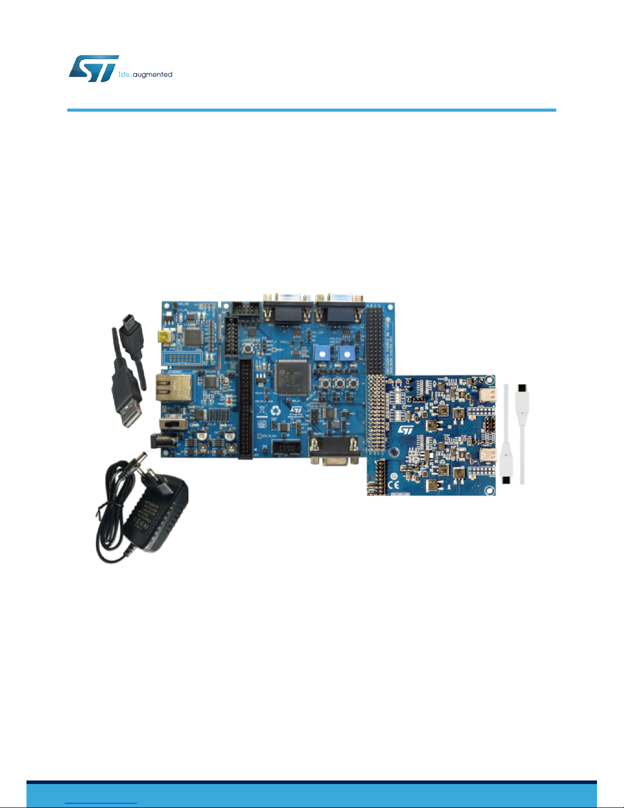
The USB Power Delivery evaluation kit is designed to help you evaluate the functions of the USB Power Delivery protocol stack
implemented on the SPC58EC80E5 Chorus line of 32-bit automotive microcontrollers based on Power Architecture®
technology
, with 4 MB of flash memory.
You can also use the AEKD-USBTYPEC1 to prototype USB Power Delivery solutions to power compatible consumer devices
via the USB Type-C™ ports.
Figure 1. AEKD-USBTYPEC1 USB Power Delivery evaluation kit
How to use the AEKD-USBTYPEC1 USB Power Delivery evaluation kit
UM2451
User manual
UM2451 - Rev 1 - August 2018
For further information contact your local STMicroelectronics sales of
fice.
www.st.com
Page 2
1 Evaluation kit overview
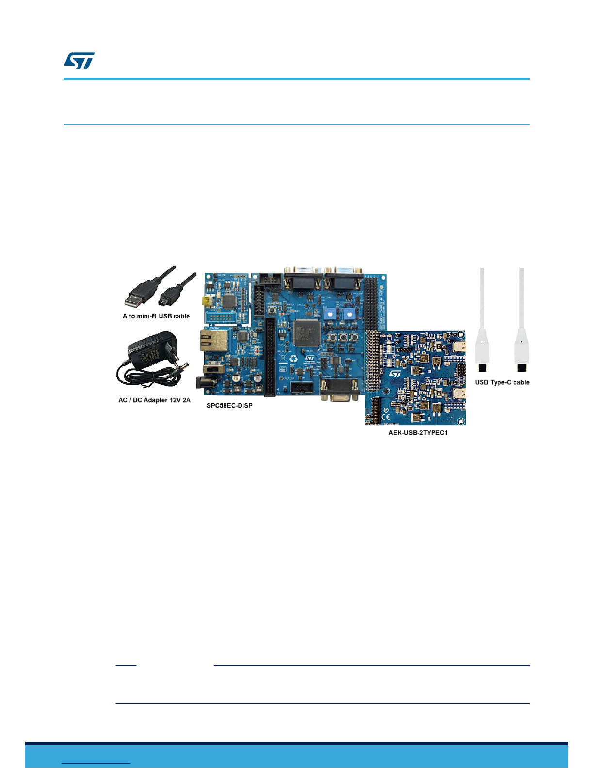
The AEKD-USBTYPEC1 kit consists of:
•
An AEK-USB-2TYPEC1 dual-port USB Type-C interface board.
• An SPC58EC-DISP discovery board hosting a SPC58EC80E5 Chorus line 4 MB flash memory, 32-bit
automotive microcontroller.
• A 1-Amp 12-Volt power supply for the SPC58EC-DISP board.
• A mini-B USB to USB Type-A cable to connect the MCU programmer.
• A USB Type-C to USB Type-C cable (not electronically marked).
• The STSW-USB2TYPEC1 flash image firmware and the related software package.
Figure 2. AEKD-USBTYPEC1 kit
The AEK-USB-2TYPEC1 interface board hosts a pair of STUSB1702Y automotive grade USB Type-C controllers;
one for each USB Type-C port. The board contains a dual Transil™ array ESDA25LY and very low capacitance
USBLC6-2SC6Y devices for ESD protection. The status of the ports is signaled on the board through a set of
LEDs for each port. The board includes about 20 test points.
The main devices on the board are the STUSB1702Y USB Type-C controller with Tx/Rx line driver and bi-phase
marked coding (BMC), and the physical layer (PHY) protocol for USB Power Delivery stack.
The AEKD-USBTYPEC1 kit supports a 5 V, 500 mA PDO based on the electrical characteristics of the SPC58EC-
DISP. To extend the range of PDOs, you can add an external power board, not included in the kit.
The software package contains the following elements:
• The firmware for the SPC58EC-DISP discovery board (already pre-loaded on the board).
• A complex driver for the STUSB1702Y USB Type-C controller.
• An SPC5-STUDIO library plugin with the USB Power Delivery software stack.
• A demo application with predefined 5 V 500 mA PDO.
The standard USB Type-C cable provided in the kit is not electronically marked. It is not suitable for currents
above 3 A and does not support USB 3.1 Gen1 or Gen2 signaling.
The USB Power Delivery Consumer role device may be a compatible mobile phone or a tablet accepting a 5 V,
500 mA PDO. You can add an external Power Board to increase the range of available PDOs. Alternatively, you
can use the P-NUCLEO-USB002 demo kit as a consumer device.
RELATED LINKS
3 Software package with firmware and USB PD project on page 10
http://www
.usb.org/home
UM2451
Evaluation kit overview
UM2451 - Rev 1
page 2/22
Page 3
1.1 LED signals
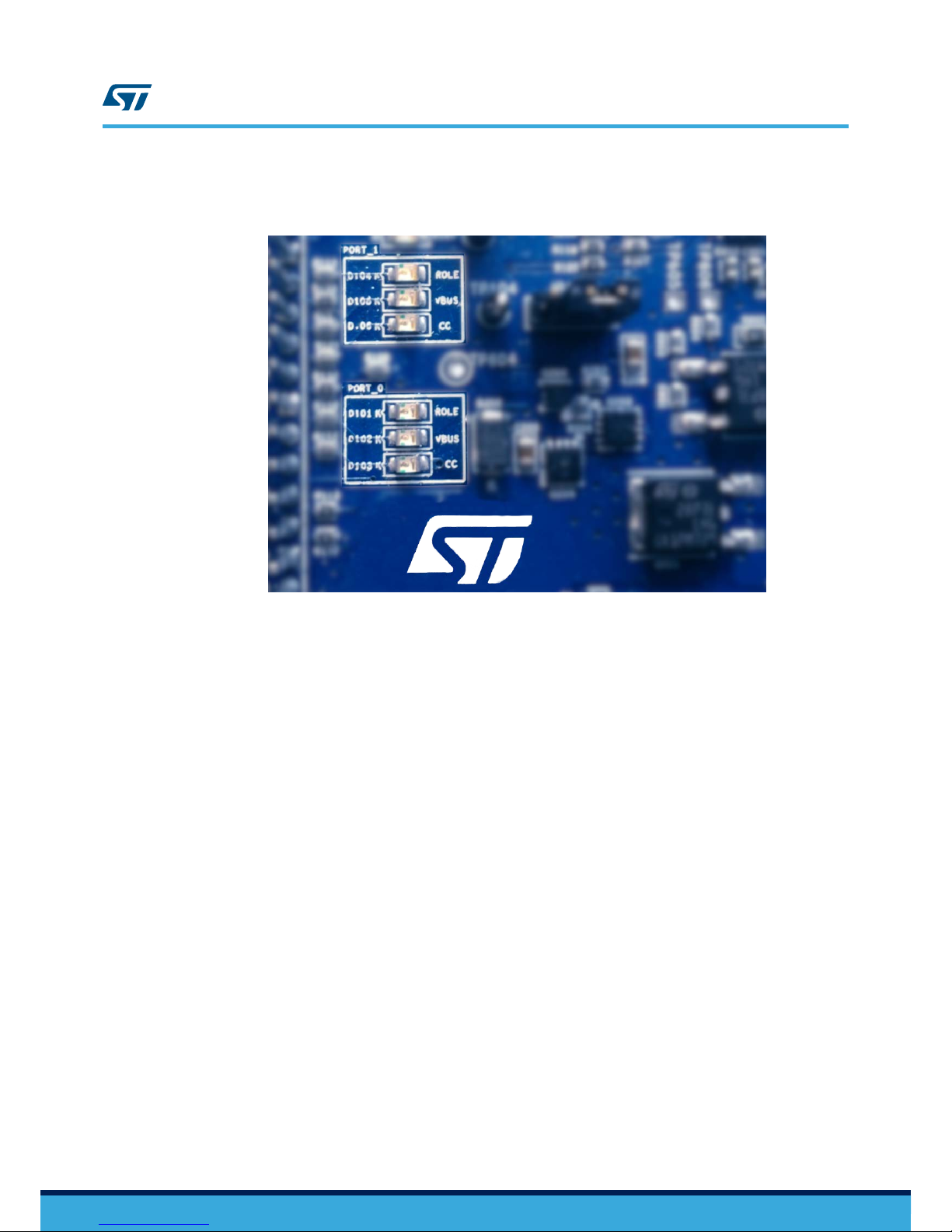
Figure 3. Port status LEDs on the AEK-USB-2TYPEC1
The AEK-USB-2TYPEC1
interface board has the following status LEDs for each port:
1. Role: emits a continuous variable blue flashing light at about 1Hz indicating the device is a provider.
2. VBUS: emits a constant green light when the power negotiation has completed (i.e., the Explicit condition is
reached). The provider can now begin to supply the negotiated power to the consumer.
3. CC: emits different orange flashing sequences to indicate the following conditions:
a. flashes at about 1Hz: CC1 line is connected.
b. flashes twice followed by a pause: CC2 line is connected.
Note: The connected Configuration Channel (CC) indicates the direction of the USB cable connection, given the cable
reversibility allowed by the USB Type-C standard.
UM2451
LED signals
UM2451 - Rev 1
page 3/22
Page 4
2 How to use the AEKD-USBTYPEC1 kit
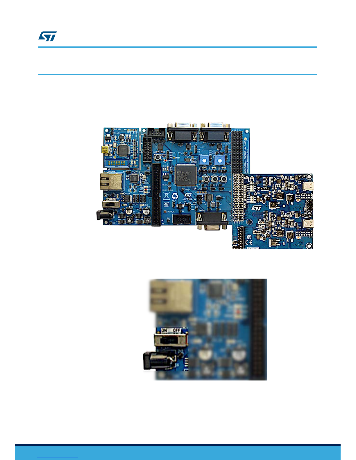
Step 1. Plug the AEK-USB-2TYPEC1 board on the SPC58EC-DISP
The AEK-USB-2TYPEC1 is plugged into the 4x37 male pin connector of the SPC58EC-DISP
board via
the 4x20 female pin connector from pins A18 to D37 (refer to pin numbering indications on the board).
Figure 4. AEKD-USBTYPEC1 plugged on SPC58EC-DISP
Step 2. Connect the 1-Amp 12-V
olt power supply plug into the socket located on the SPC58EC-DISP and then
turn on the board.
Figure 5. Voltage supply socket and power switch on SPC58EC-DISP
After about 5 seconds, the ROLE LED on the AEK-USB-2TYPEC1 board should start blinking at rate of
1 Hz to indicate the board is a provider.
Step 3. Connect a consumer to a USB Type-C port
You can connect one or two consumers to one or both USB Type-C ports. The USB Type-C ports
supply 5 V each and 500 mA in total for both ports.
UM2451
How to use the AEKD-USBTYPEC1 kit
UM2451 - Rev 1
page 4/22
Page 5

Power negotiation begins when the consumer is connected. If the negotiation concludes successfully (i.e., the
“Explicit” condition is reached), the VBUS LED VBUS emits a green light.
If the consumer has a compatible PDO but it is not able to reach the “Explicit” condition, try to:
•
Use another USB Type-C port on the consumer device, if available.
• Disconnect and reconnect the USB Type-C cable.
• Switch the SPC58EC-DISP board off and on and try to connect the Consumer device again.
• Try a different USB Type-C cable.
2.1 Pin mappings for an external power board
The power negotiation protocol between consumer and provider agrees on a PDO that is actuated on a power
board (not included in the kit).
The microcontroller on the SPC58EC80E5 board can direct the power supplied by an external power board
through GPIOs on the male connector on the AEK-USB-2TYPEC1 interface board.
Note:
The external power board you use must be compatible with the consumer power requirements.
If the desired voltage is not provided within the time-out interval specified in the USB Power Delivery protocol, the
STUSB1702Y informs the microcontroller that the voltage output in the port is not actuated and the
microcontroller resets the system and starts power negotiation again.
Note: The connection of the external power board may require modifications in the software stack.
Communication between the STUSB1702Y and microcontroller is based on SPI protocol, where the
STUSB1702Y has the master role in the communication.
The following figure shows the 4x37 connector on the SPC58EC-DISP board. The portion occupied by the AEK-
USB-2TYPEC1 is zoomed to show the pins for the external power board (in green) and for the interface board (in
blue).
UM2451
Pin mappings for an external power board
UM2451 - Rev 1
page 5/22
Page 6
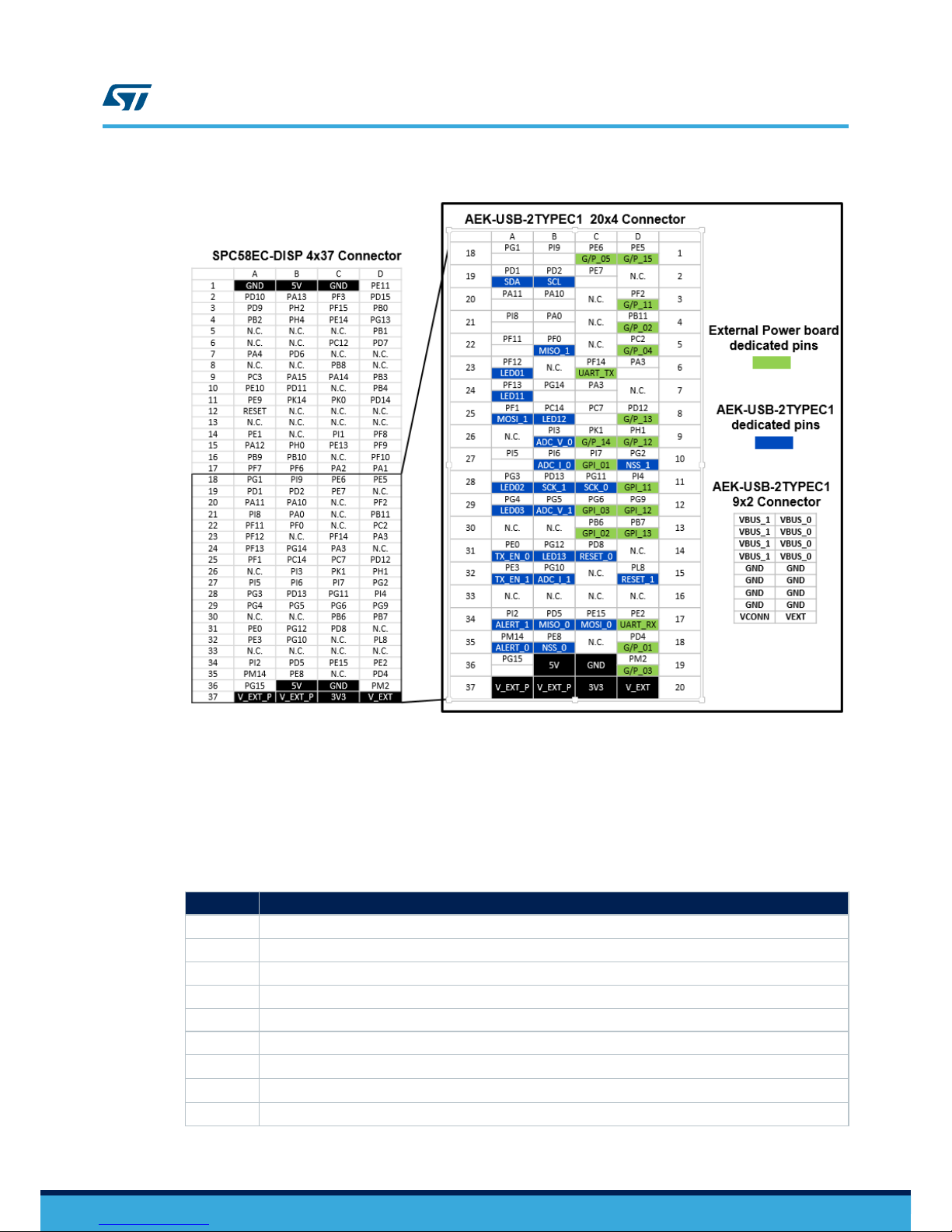
Figure 6. Pin mapping of the AEK-USB-2TYPEC1 connectors
Connectors CN1 (4x20 male pin connector) and CN2 (2x9 male pin connector) are located on the opposite side of
the USB T
ype-C ports. CN1 is for the control signals and CN2 is for the power supply. In the figure, the green
cells in CN1 represent the pins to drive the external power board. The cell labels starting with “Pxx” represent the
microcontroller ports mapped to the 4x37 connector. The microcontroller ports can assume different functions
depending on the register settings of a specific microcontroller.
The following table contains the descriptions of the interface board pins.
Table 1. AEK-USB-2TYPEC1 4x20 connector interface board pin descriptions
Pin Name Description
ADC_I_0 ADC channel to convert the current value provided by VBUS on to port 0.
ADC_I_1 ADC channel to convert the current value provided by VBUS on to port 1.
ADC_V_0 ADC channel to convert the voltage value (VBUS) applied to port 0.
ADC_V_1 ADC channel to convert the voltage value (VBUS) applied to port 1.
ALERT_0 Alert pin of STUSB1702Y device managing port 0
ALERT_1 Alert pin of STUSB1702Y device managing port 1
LED01
(1)
To command the LED “ROLE” for port0
LED11
(2)
To command the LED “ROLE” for port1
LED02 To command the LED “VBUS” for port0
UM2451
Pin mappings for an external power board
UM2451 - Rev 1
page 6/22
Page 7
Pin Name Description
LED12 To command the LED “VBUS” for port1
LED03 To command the LED “CC” for port0
LED13 To command the LED “CC” for port1
MISO_0 Master Input Slave Output (MISO) of SPI protocol for port 0
MISO_1 Master Input Slave Output (MISO) of SPI protocol for port 1
MOSI_0 Master Output Slave Input (MOSI) of SPI protocol for port 0
MOSI_1 Master Output Slave Input (MOSI) of SPI protocol for port 1
NSS_0 Slave Select (NSS) of SPI protocol for port 0
NSS_1 Slave Select (NSS) of SPI protocol for port 1
SCK_0 Serial Clock (SCK) of SPI protocol for port 0
SCK_1 Serial Clock (SCK) of SPI protocol for port 1
SCL
Serial Clock of I2C
SDA
Serial Data of I2C
RESET 0 Used to reset the STUSB1702Y for port 0
RESET 1 Used to reset the STUSB1702Y for port 1
TX_EN_0 Used by slave to ask master to start the SPI communication for port 0 by resetting the NSS pin
TX_EN_1 Used by slave to ask master to start the SPI communication for port 1 by resetting the NSS pin
1.
It is recommended to remove the jumper from the jumper pins JP46 on the SPC58EC_DISP board.
2. It is recommended to remove the jumper from the jumper pins JP48 on the SPC58EC_DISP board.
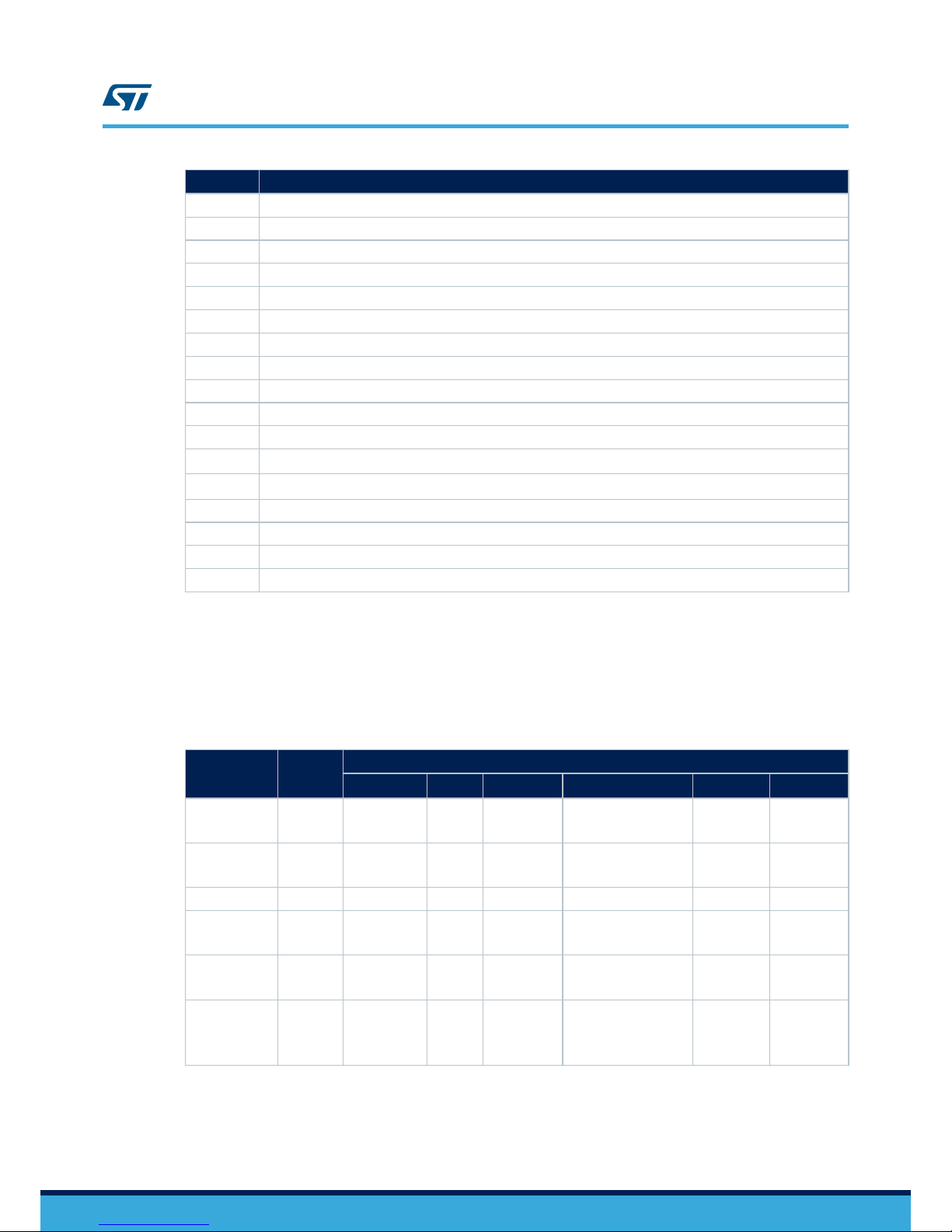
The following table shows the mapping between the external power board pins and the microcontroller ports. The
table also shows the functions that can be assigned to each pin. Only one function can be mapped to a single
microcontroller port at a time.
Table 2. AEK-USB-2TYPEC1 4x20 connector power board pin description
Pin name Port #
Function[module instance]
GPIO
(1)
CAN SPI
ADC (12 bit)
(2)
LIN
Timer
(3)
G/P_01 PD[4] GPIO52
RX[1]
RX[3]
SCK[0]
SCK[7]
- TXD[3]
UC6
UC4
G/P_02 PB[11] GPIO27 -
CS0[0]
CS2[2]
- RXD[2]
UC24
UC5
G/P_03 PM[2] GPIO194 RX[6] SOUT[1] - - UC9
G/P_04 PC[2]
GPIO34
EIRQ10
- - - TXD[15]
UC8
UC10
G/P_05 PE[6] GPIO70 RX[0]
CS1[0]
CS1[1]
- RXD[1]
UC4
UC2
G/P_11 PF[2]
GPIO82
EIRQ6
RX[6]
CS2[1]
SOUT[1]
SOUT[3]
INJ_TRG
NOR_TRG
RXD[2]
RXD[8]
UC20
UC12
UM2451
Pin mappings for an external power board
UM2451 - Rev 1
page 7/22
Page 8

Pin name Port #
Function[module instance]
GPIO
(1)
CAN SPI
ADC (12 bit)
(2)
LIN
Timer
(3)
G/P_12 PH[1] GPIO113 RX[3]
SCK[2]
CS0[6]
SOUT[6]
SIN[6]
- RXD[6] UC15
G/P_13 PD[12] GPIO60 -
CS7[0]
SIN[3]
SOUT[3]
SIN[4]
SOUT[4]
SIN[6]
EXT_DEC0
ANS[15]
ANF[15]
TXD[14]
UC14
UC16
G/P_14 PK[1] GPIO161 - SCK[4] - - UC24
G/P_15 PE[5] GPIO69 TX[0]
CS0[0]
CS0[1]
CS0[7]
- RXD[15]
UC3
UC1
GPI_01 PI[7] GPIO135 - -
ANS[50]
ANF[50]
- -
GPI_02 PB[6] GPIO22 - -
ANS[48]
ANF[48]
- -
GPI_03 PG[6] GPIO102 - -
ANS[44]
ANF[44]
- -
GPI_11 PI[4] GPIO132 - -
ANS[40]
ANF[40]
- -
GPI_12 PG[9] GPIO105 - -
ANS[53]
ANF[53]
- -
GPI_13 PB[7] GPIO23 - -
ANS[47]
ANF[47]
- -
UART_TX PF[14]
GPIO94
EIRQ17
- - -
TXD[5]
TXD[14]
UC26
UART_RX PE[2]
GPIO66
EIRQ1
1
-
CS3[3]
SIN[3]
SIN[4]
SOUT[3]
SOUT[4]
ANS[13]
ANF[13]
RXD[5]
UC13
UC15
1.
GPIO = General Purpose I/O; EIRQ = External interrupt.
2. INJ_TRG = Injected Conversion Trigger; NOR_TRG = Normal Conversion Trigger; EXT_DEC = External Decoder Address;
ANS[x] = Standard Analog Channel x; ANF[x] = Fast Analog Channel x
3. Enhanced Modular IO Subsystem (eMIOS) provides functionality to generate or measure time events on up to 32 unified
channels (UCs).
RELATED LINKS
3.3 Configuration of the USB-PD library through SPC5-Studio on page 11
UM2451
Pin mappings for an external power board
UM2451 - Rev 1
page 8/22
Page 9

2.1.1 Output voltage selection
The following table shows the 3-bit binary combinations to select specific output voltage levels for USB Type-C
port0 and USB T
ype-C port1.
The pins in the table are relative to the AEK-USB-2TYPEC1 board. The pins are digital inputs, so “L” represents
0 V and “H” represents 3.3 V.
Table 3. Output voltage selection
Output Voltage
USB Type-C port0 USB Type-C port1
Pin D18 Pin C9 Pin D9 Pin D5 Pin D4 Pin D3
5 V L L L L L L
9 V H L L H L L
15 V H H L H H L
20 V H H H H H H
The table represents the default settings provided in the STSW
-USB2TYPEC1 software. You can change these
settings in SPC5-STUDIO.
2.1.2 Connection of an external power board (not included in the kit)
The following figure shows the connection of an external power board to the CN1 and CN2 connectors on the
AEK-USB-2TYPEC1 board.
Figure 7. Connection of an external power board
UM2451
Pin mappings for an external power board
UM2451 - Rev 1
page 9/22
Page 10

3 Software package with firmware and USB PD project
The software package for the kit is composed of the following parts:
1. STSW
-USB2TYPEC1 firmware: a zip file containing the flash image of the USB Power Delivery demo
firmware already loaded on the SPC58 microcontroller. You can download updates from the STSW-
USB2TYPEC1 page on www.st.com.
2. USB Power Delivery SPC5-STUDIO project: contains the complex driver for STUSB1702Y device, the USB
Power Delivery stack, and a demo application.
RELATED LINKS
1 Evaluation kit overview on page 2
3.1 How to program SPC58 microcontroller present on SPC58EC-DISP
The firmware STSW
-USB2TYPEC1 is pre-loaded on the discovery board SPC58EC-DISP. In the zip file, the
“.wsx” represents the hook file for the Universal Debug Engine® (UDE) to burn the USB-PD code onto the SPC58
microcontroller flash memory. Follow the procedure below to burn the code onto the flash memory of SPC58:
Step 1. Download and install SPC5-UDESTK-SW USB/JTAG debugger from www.st.com
Step 2. Connect the mini-B USB cable between your PC and the SPC58EC-DISP discovery board
Step 3. Turn-on the discovery board
Step 4. Run the UDE application on your PC
Step 5. In the UDE program, [Open] file st_usbpd.wsx
You will find the .wsx file in the zip in the UDE directory.
A window appears.
Step 6. In the new window, press [Program All]
A confirmation message appears in the same window when the operation is complete. At this point, the
firmware is flashed to the microcontroller memory.
Step 7. Exit the window
Step 8. Reset the SPC58EC-DISP discovery board to run the updated firmware
3.2 How to open the SPC5 Studio project
The SPC5 Studio project gives you access to the USBPD library plugin source code. Follow the procedure below
to open the project:
Step 1. Obtain a valid username and password: send an email to credentials@spc5studio.com and specify the
following information:
–
your company name
– your project
– project target run-rate
– the date
Step 2. Open SPC5 Studio
Step 3. Go to [Help]>[Install new Software] and then click the [Add] button
UM2451
Software package with firmware and USB PD project
UM2451 - Rev 1
page 10/22
Page 11

Figure 8. Help menu in SPC5-Studio
Step 4. Enter the text “USBPD” in the name field
Step 5. Enter “usbpd.spc5studio.com” in the location field
Figure 9. Install window in SPC5-Studio
Step 6. Confirm the form
Step 7. Enter the username and password
UM2451
How to open the SPC5 Studio project
UM2451 - Rev 1
page 11/22
Page 12
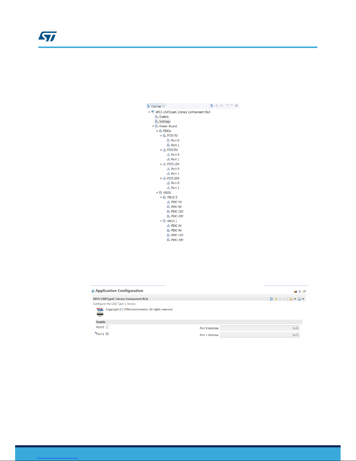
3.3 Configuration of the USB-PD library through SPC5-Studio
After you download the package, you can open the project in SPC5-Studio and configure certain settings before
you flash the firmware to the discovery board:
Figure 10. USB-PD Library structure
• Enable or disable Port 1 (enabled by default).
Note:
Port 0 is always enabled.
Figure 11. USB Type-C Port 1 toggle
UM2451
Configuration of the USB-PD library through SPC5-Studio
UM2451 - Rev 1
page 12/22
Page 13

• Enable or disable hardware CRC (enabled by default). If it is disabled, a software version is used.
Figure 12. Hardware CRC, LED signals, and T
est mode toggles
• Enable or disable LED signals (enabled by default).
•
Enable or disable hardware Test mode (disabled by default), to check the hardware.
• Enable or disable additional PDOs. The PDOs must be compliant with the external power board connected.
You can define the current capability and the port for each PDO.
Figure 13. PDO togles and output voltage selection table settings
• Configure a logic table to determine the microcontroller pin combinations required to switch between
dif
ferent power profiles.
UM2451
Configuration of the USB-PD library through SPC5-Studio
UM2451 - Rev 1
page 13/22
Page 14

Table 4. Default logic table for Port 0 and Port1
Vout_x [V] Port_sig1 Port_sig2 Port_sig3
5V L L L
9V H L L
15V H H L
20V H H H
If Test mode is enabled, you must connect a USB cable between the SPC58EC-DISP discovery board and your
PC to print debug messages to a terminal window on your PC. Configure the corresponding COM port with 38400
baud and N81.
Figure 14. SPC58EC-DISP connected to computer via USB cable
RELATED LINKS
2.1 Pin mappings for an external power board on page 5
UM2451
Configuration of the USB-PD library through SPC5-Studio
UM2451 - Rev 1
page 14/22
Page 15

4 USB Power Delivery overview
The USB Type-C and USB Power Delivery specifications allow smarter connectivity with fewer cables, less
connectors and universal chargers. The T
ype-C connector supports all the features of previous standards, and
ports can be configured to only supply power in a Provider role, only sink power in a Consumer role, or be able to
switch between both in a Dual role.
Both data and power roles can be independently and dynamically swapped using the USB Power Delivery
protocol.
Most automotive applications require support for the Provider role only. When a USB device is connected, the
Provider and the device (Consumer) negotiate a contract for the power objects through configuration channels.
The message exchange between Provider and Consumer are listed below:
1. The Provider sends a Source Capabilities message to the Consumer, advertising its power
capabilities.
2. The device then sends a Request for one of the advertised power profiles.
3. The provider accepts or rejects this request according to its power balance
4. If confirmed, provider sends as an Accept message to the device
5. The provider then switches to the requested power profile and sends a PS_Ready confirmation message
Each received message is acknowledged with a GoodCRC to confirm correct reception. Incorrect receptions are
ignored and persistent communication errors should trigger a soft reset to re-establish communication. If the error
persists, a hard reset is performed.
UM2451
USB Power Delivery overview
UM2451 - Rev 1
page 15/22
Page 16

5 ST’s AutoDevKit development initiative
AutoDevKit governs the hardware and software connection between micro discovery boards and specific function
boards for applications like stepper motor control, led control, etc.
Each function board has a dedicated driver with abstractions for the specific microcontroller peripherals to ensure
portability between platforms. The drivers are SPC5 Studio plugins that are instantiated dynamically by the tool
according to the microcontroller used for the development. The instantiation process generates the appropriate
source code and indicates how a function board should be connected to the chosen discovery board.
5.1 AutoDevKit for AEKD-USBTYPEC1
The AEKD-USBTYPEC1 evaluation kit consists of a discovery board (SPC58EC-DISP) and a USB T
ype-C dual
port interface function board (AEK-USB-2TYPEC1).
The 20x4 function board female connector on the function board is connected to the 4x37 male connector on the
discovery board from the 18th pin to 37th pin. These pins cover the following purposes:
1. The connection between the USB function board and the discovery board.
2. The connection of a power board (not included in the demo kit) and the discovery board to be plugged on
top of the function board 4x20 male connector.
Lines 1 to 17 on the discovery board 4x37 connector can be used to connect additional function boards according
to the AutoDevKit development initiative.
UM2451
ST’s AutoDevKit development initiative
UM2451 - Rev 1
page 16/22
Page 17

Revision history
T
able 5. Document revision history
Date Version Changes
26-Jul-2018 1 Initial release.
UM2451
UM2451 - Rev 1
page 17/22
Page 18

Contents
1 Evaluation kit overview ............................................................2
1.1 LED signals ...................................................................2
2 How to use the AEKD-USBTYPEC1 kit .............................................4
2.1 Pin mappings for an external power board .........................................5
2.1.1 Output voltage selection ...................................................8
2.1.2 Connection of an external power board (not included in the kit) .....................9
3 Software package with firmware and USB PD project ..............................10
3.1 How to use STSW
-USBTYPEC1 firmware.........................................10
3.2 How to open the SPC5 Studio project ............................................10
3.3 Configuration of the USB-PD library through SPC5-Studio ...........................11
4 USB Power Delivery overview.....................................................15
5 ST’s AutoDevKit development initiative ...........................................16
5.1 AutoDevKit for AEKD-USBTYPEC1 ..............................................16
Revision history .......................................................................17
UM2451
Contents
UM2451 - Rev 1
page 18/22
Page 19

List of figures
Figure 1. AEKD-USBTYPEC1 USB Power Delivery evaluation kit ........................................1
Figure 2. AEKD-USBTYPEC1 kit ..............................................................2
Figure 3. Port status LEDs on the AEK-USB-2TYPEC1 ...............................................3
Figure 4. AEKD-USBTYPEC1 plugged on SPC58EC-DISP ............................................4
Figure 5. V
oltage supply socket and power switch on SPC58EC-DISP ....................................4
Figure 6. Pin mapping of the AEK-USB-2TYPEC1 connectors ..........................................6
Figure 7. Connection of an external power board ...................................................9
Figure 8. Help menu in SPC5-Studio........................................................... 11
Figure 9. Install window in SPC5-Studio ........................................................ 11
Figure 10. USB-PD Library structure............................................................ 12
Figure 11. USB Type-C Port 1 toggle ........................................................... 12
Figure 12. Hardware CRC, LED signals, and Test mode toggles......................................... 13
Figure 13. PDO togles and output voltage selection table settings ....................................... 13
Figure 14. SPC58EC-DISP connected to computer via USB cable ....................................... 14
UM2451
List of figures
UM2451 - Rev 1
page 19/22
Page 20

List of tables
T
able 1. AEK-USB-2TYPEC1 4x20 connector interface board pin descriptions................................ 6
Table 2. AEK-USB-2TYPEC1 4x20 connector power board pin description ..................................7
Table 3. Output voltage selection ............................................................... 9
Table 4. Default logic table for Port 0 and Port1 .................................................... 14
Table 5. Document revision history .............................................................17
Table 6. AEKD-USBTYPEC1 kit terminology ...................................................... 21
UM2451
List of tables
UM2451 - Rev 1
page 20/22
Page 21

Glossary
T
able 6. AEKD-USBTYPEC1 kit terminology
Term Definition
Power-data
object (PDO)
As per USB Power Delivery Specification, the PDO represents the format of data exchanged between
provider and consumer to define the power capability in terms of output voltage and maximum current.
SPC5-STUDIO
It is a software development tool built on Eclipse Plug-in Development Environment (PDE). With an intuitive
look-
and-feel, it provides all the features to design, build and deploy automotive embedded applications for
SPC5 32-bit Power Architecture® microcontrollers.
Eclipse
It is an integrated development environment (IDE) used primary for developing Java applications, but also to
develop applications in other programming languages using plug-ins.
Universal Serial
Bus (USB)
T
ype-C
It is the latest interface built on USB technology to serve newer computing platforms and devices as they
trend toward smaller
, thinner and lighter form-factors.
It is a 24-pin double-sided USB connector system.
A new USB connector ecosystem is necessary to address the evolving needs of platforms and devices
maintaining a sort of compatibility with the existing connector form-factors. The standard USB Type-C
provide up to 15W.
USB Power
Delivery
The USB Power Delivery specification defines a power delivery system covering all elements of a USB
system.
This
specification describes the architecture, protocols, power supply behaviour, connectors and cabling
necessary for managing power delivery over USB up to 100W. This specification is intended to be fully
compatible and extend the existing USB infrastructure.
Complex driver
It is a software written to implement functionalities related to a specific hardware. The peculiar point is that
the
software does not directly access hardware functions (e.g. registers, pins, etc.), but takes advantage of
platform specific libraries. With this approach, the software is portable across various platforms.
UM2451
UM2451 - Rev 1
page 21/22
Page 22

IMPORTANT NOTICE – PLEASE READ CAREFULLY
STMicroelectronics NV and its subsidiaries (“ST”) reserve the right to make changes, corrections, enhancements, modifications, and improvements to ST
products and/or to this document at any time without notice. Purchasers should obtain the latest relevant information on ST products before placing orders. ST
products are sold pursuant to ST’
s terms and conditions of sale in place at the time of order acknowledgement.
Purchasers are solely responsible for the choice, selection, and use of ST products and ST assumes no liability for application assistance or the design of
Purchasers’ products.
No license, express or implied, to any intellectual property right is granted by ST herein.
Resale of ST products with provisions different from the information set forth herein shall void any warranty granted by ST for such product.
ST and the ST logo are trademarks of ST. All other product or service names are the property of their respective owners.
Information in this document supersedes and replaces information previously supplied in any prior versions of this document.
© 2018 STMicroelectronics – All rights reserved
UM2451
UM2451 - Rev 1
page 22/22
 Loading...