

Page 1
Schrift 310 650 – 2012/02/06 Print 330 650 – 2012/02/06 1
ASV Stübbe GmbH & Co. KG • Hollwieser Straße 5 • D-32602 Vlotho • Fon +49(0) 57 33 - 7 99-0 • Fax +49 (0)57 33 - 799-50 00 • www.asv-stuebbe.de • contact@asv-stuebbe.de
Mounting and Instruction Manual
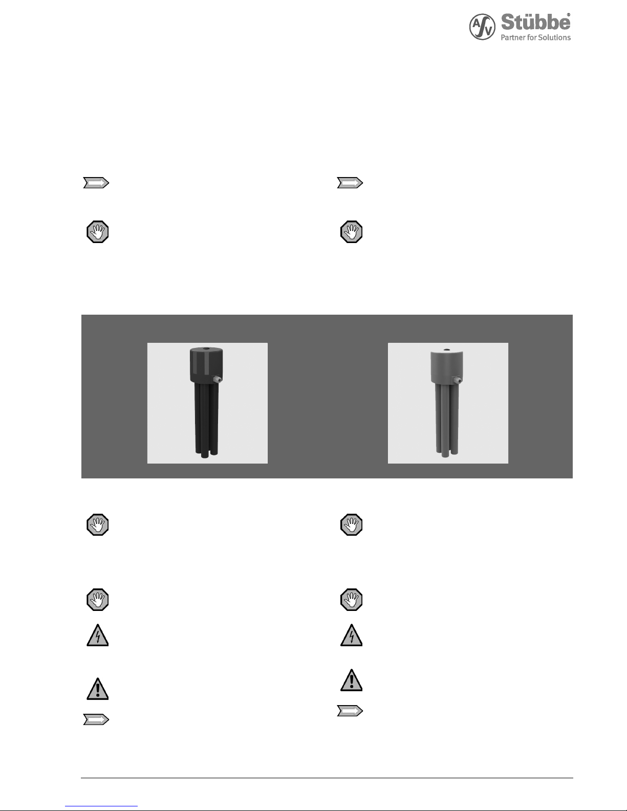
Level switch
NIS
The NIS is not approved as an overfill
prevention system as per §19 WHG
(Federal Water Act)!
ATTENTION
Before installing and commissioning it is
imperative to read these instructions.
It is prohibited to perform alterations to the
level switch that have an effect on the specified
technical data and mode of operation.
Montage- und Betriebsanleitung
Niveauschalter
NIS
Der NIS ist nicht als Überfüllsicherung
gemäß §19 WHG zugelassen!
ACHTUNG
Diese Anweisung unbedingt vor der Installation
und Inbetriebnahme lesen!
Änderungen am Niveauschalter, die
Auswirkungen auf die angegebenen
technischen Daten und die Funktionsweise
haben, sind verboten!
NIS NIS
1. Sicherheitshinweise
Lesen Sie unbedingt diese Anweisungen vor
Beginn aller Arbeiten. Sie dienen zu Ihrer
Sicherheit und einer korrekten Funktionsweise
der zu installierenden Armatur. Bei Nichtbeachtung können schwerste Verletzungen
oder Sachschäden an der Anlage entstehen.
1.1 Sicherheitssymbole und Bedeutung
Unmittelb a r drohende G e f a hr!
Bei Nichtbeachtung drohen Tod oder schwerste
Verletzungen.
Unmittelbar drohende Gefahr!
Bezeichnet eine mögliche Gefährdung durch
elektrische Spannung. Bei Nichtbeachtung des
Hinweises können Tod oder schwerste
Verletzungen eintreten.
Möglicherweise drohende Gefahr!
Bei Nichtbeachtung drohen schwere
Verletzungen und/oder Sachschäden.
Wichtige In f o rmat i o n!
Bei Nichtbeachtung können Verletzungen und/
oder Sachschäden entstehen.
1. Safety instructions
It is imperative to read these instructions prior
to starting any work. They are intended to
ensure your safety and the correct mode of
operation of the valve to be installed. Nonobservance of this information can lead to most
severe injuries of damage to plant assets.
1.1 Safety symbols and meaning
Imminent danger
Non-observance can lead to death or most
severe injuries.
Imminent danger
Indicates a possible hazard emanating from
electrical voltage. Non-observance of this note
can lead to death or most severe injuries.
Possible danger
Non-observance can lead to severe injury and/
or damage to assets.
Important information
Non-observance can lead to personnel injury
and/or damage to assets.
Page 2
2
ASV Stübbe GmbH & Co. KG • Hollwieser Straße 5 • D-32602 Vlotho • Fon +49(0) 57 33 - 7 99-0 • Fax +49 (0) 57 33 - 7 99-50 00 • www.asv-stuebbe.de • contact@asv-stuebbe.de
1.2 Installation und Inbetriebnahme
Ein sicherer Betrieb des Niveauschalters setzt
voraus, dass der Monteur für die Installation
und Inbetriebnahme folgende Qualifikationen
besitzt bzw. sicherheitsbewusste
Arbeitsabläufe berücksichtigt!
1.2.1 Der Monteur muss eine fachbezogene Qualifikation im Kunststoffrohrleitungsbau besitzen.
1.2.2 Der Monteur hat sich vor Beginn aller Arbeiten
bei dem Betreiber der Anlage über die
Gefahren, die von Anlage/Medium ausgehen
können, zu informieren und hat diesbezügliche
Schutz- und Sicherheitsmaßnahmen zu
befolgen.
1.2.3 Der Monteur hat sicherzustellen, dass das
Einschalten/Anfahren der Anlage bei der
Installation, Wartung oder Instandsetzung
nicht möglich ist. Strom- und Druckluftversorgung sind sicher vom Netz zu trennen
und gegen unbefugtes Einschalten zu sichern.
1.2.4 Der Monteur hat sicherzustellen, dass die
Rohrleitungskomponenten unter Beachtung der
Sicherheitsvorschriften drucklos sind, entleert
und dekontaminiert wurden. Nachlaufende
Mediumreste sind aufzufangen.
1.3 Bestimmungsgemäße Verwendung
Zur Überwachung von Flüssigkeitsständen in
drucklosen Behältern oder offenen Gruben.
Als Signalgeber bei Unterschreitung sowie bei
Überschreitung einer festgelegten
Füllstandshöhe.
Infolge der Luftabsorptionsfähigkeit der
meisten Flüssigkeiten sind die Tauchrohre in
gewissen Zeitabständen zu belüften, um
Schaltpunktverschiebungen zu vermeiden!
1.3.1 Arbeitsweise
Der Niveauschalter NIS enthält 1 bis 4
Membrandruckschalter und die gleiche Anzahl
mit ihnen verbundener Tauchrohre.
Steigt das Flüssigkeitsniveau, wird die in den
Tauchrohren befindliche Luft komprimiert.
Bei einer Druckerhöhung von max. 10 mbar
(Niveauunterschied von 100 mm H2O), wird
über die Membrane ein Sprungschalter
betätigt.
Sinkt das Niveau um max. 50 mm, entspannt
sich die im Tauchrohr befindliche Luft und es
erfolgt die Rückschaltung.
1.3.2 Beständigkeitsprüfung
Alle mediumberührten Bauteile des
Niveauschalters müssen nach der ASV
Beständigkeitsliste für das verwendete Medium
»beständig« sein.
ASV-Beständigkeitsliste beachten!
1.3.3 Temperaturprüfung
PVC-U: bis max. 60°C
PP: bis max. 80°C
1.3.4 Typenschildangabe
Die Typenschildangaben müssen mit den
Bestell-/Auslegungsdaten übereinstimmen.
2. Installationshinweise
Beachten Sie die Sicherheitshinweise!
Des Weiteren sind zu beachten:
DIN, DIN/ISO, DVS, nationale und
internationale Normen, die Verkleberichtlinien
(PVC-U, PVC-C) bzw. die Schweißrichtlinien
(PP, PVDF) für Kunststoffarmaturen.
1.2 Installation and commisioning
Safe operation of the level switch requires that
the fitter carrying out installation and start-up
has the following qualifications and takes into
account safety relevant operating sequences.
1.2.1 The fitter must have expert qualifications in
plastic pipework construction.
1.2.2 Prior to starting any work, the fitter must
obtain information from the user/owner of the
system regarding any potential hazards
emanating from the system/medium and must
observe all pertinent protection and safety
measures accordingly.
1.2.3 The fitter must make sure that switching on/
starting up of the system is impossible during
installation, maintenance or repairs. Reliably
disconnect the power supply as well as the
compressed air supply from the networks and
prevent unauthorised activation.
1.2.4 The fitter must ensure that the pipework
components are depressurised, emptied and
decontaminated while taking the safety
instructions into account. Collect any residual
fluid accordingly.
1.3 Intended use
For monitoring fluid levels in pressureless
containers or open pits.
For signalling if the level exceeds or falls below
a set filling level
Due to the air absorption properties of most
fluids, aerate the immersion tubes at regular
intervals to prevent any displacement of the
switching points.
1.3.1 Operating principle
The level switch NIS contains 1 to 4 diaphragm
pressure switches and the same number of
immersion tubes connected to them.
When the fluid level rises, the air in the
immersion tubes is compressed.
At a pressure increase of max. 10 mbar (level
difference of 100 mm H2O), the diaphragm
activates a snap-action switch.
If the level drops by a maximum of 50 mm, the
air pressure in the immersion tube drops and a
reset occurs.
1.3.2 Resistance test
All components of the level switch getting into
contact with the medium must be »resistant«
according to the ASV resistance guide.
1.3.3 Temperature test
PVC-U: up to max. 60°C
PP: up to max. 80°C
1.3.4 Identification plate
The information on the identification plate must
coincide with the order/design data.
2. Installation notes
Adhere to the safety instructions.
In addition observe:
DIN, DIN/ISO, DVS*, national and international
standards, the regulations for solvent welding
(PVC-U, PVC-C) or fusion welding (PP, PVDF) of
thermoplastic valves.
*DVS = German Welding Society
Page 3
3
ASV Stübbe GmbH & Co. KG • Hollwieser Straße 5 • D-32602 Vlotho • Fon +49(0) 57 33 - 7 99-0 • Fax +49 (0) 57 33 - 7 99-50 00 • www.asv-stuebbe.de • contact@asv-stuebbe.de
2.1 Abmessungen
Siehe Datenblatt:
Niveauschalter NIS »310074«.
2.2 Einbaurichtung
Senkrecht, von oben nach unten.
2.3 Anschluss der Tauchrohre
2.3.1 PVC-Klebemuffen nach DIN ISO.
2.3.2 PP-Schweißmuffen nach DIN ISO.
Für die Gehäuse/Tauchrohrverbindung aus PP
bei den Varianten (NIS 2, NIS 3, NIS 4) ist
Spezialwerkzeug notwendig.
Bestellen Sie diese Varianten stets bei ASV.
2.4 Schaltpunkte »Abb. 1«
Für den jeweiligen Schaltpunkt muss der
Monteur eine 8 mm Bohrung, die 100 mm unter
dem gewünschten Schaltpunkt liegt, in das
Tauchrohr bohren.
2.5 Installation »Abb. 2«
Der Niveauschalter kann durch Gewindeensate
am Gehäuseunterteil, oder als Zubehör
erhältlich, durch Flansch oder Halteplatte, auf
den drucklosen Behälter montiert werden.
2.6 Elektrischer Anschluss »Abb. 3«
Die Installation des Niveauschalters an das
Strom-/Steuernetz ist nur von autorisierten
und qualifizierten Monteuren vorzunehmen!
2.6.1 Elektrische Schaltleistung
max. Werte bei ohmscher Belastung
• AgNi-Kontakte: 6(1,5)A / 250 VAC
• AgNi-Kontakte: 2A / 24 VDC
• Vergoldeter Kontakt: 100 mA / 24 VAC
• Vergoldeter Kontakt: 30 mA / 24 VDC
2.6.2 Elektrischer Anschluss
• AMP-Flachstecker 6,3 x 0,8 nach DIN 46244
• Kabelverschraubung PG 16
• Schutzart IP 65
2.7 Technische Daten
2.7.1 Membrandruckschalter
• Membrane: EPDM oder FPM
• Schaltdruck: 100 mm WS = ca. 10 mbar
• Rückschaltdruck: 50 mm WS = ca. 5 mbar
• Druckbelastung der Schalter: max. 0,5 bar
• Schalttoleranz: ±10% vom jeweiligen
Schaltdruck, jedoch min. ±7,5 mm WS = ca.
0,75 mbar
Die Druckeinstellschrauben auf dem
Membrandruckschalter dürfen nicht verstellt
werden.
Eine Verstellung der Schrauben verursacht
undefinierte Schaltpunktverschiebungen!
3. Wartung und Instandsetzung
Die Schaltfunktion sollte in gewissen
Zeitintervallen, die vom Betreiber festzulegen
ist, geprüft werden.
Ist eine Verschiebung der Schaltpunkte zu
erkennen, muss das Tauchrohr belüftet
werden. Hierzu ziehen Sie bitte den
Niveauschalter aus dem Behälter und setzen
ihn anschließend senkrecht wieder ein.
2.1 Dimensions
See data sheet:
Level switch NIS »330074«.
2.2 Installation direction
Vertically, from top to bottom.
2.3 Connection of the immersion tubes
2.3.1 PVC socket ends for solvent welding acc. to DIN
ISO.
2.3.2 PP socket ends for fusion welding acc. to DIN
ISO.
For the version NIS 2, NIS 3 and NIS 4, made
out of PP, you need for the connection from
housing and immersion tubes special tools.
Please order this veriants by ASV.
2.4 Switching points »Abb. 1«
The switching points can be determined by
drilling an 8 mm hole into the tube which needs
to be 100mm lower on the tube as the required
switching level. These holes have to be drilled
by the installing assembly worker.
2.5 Installation »Abb. 2«
The level switch can be installed onto the nonpressurised container by means of female
threads or optionally by a flange or fixation
plate, both of which are available as accessory.
2.6 Electrical Connection »Abb. 3«
Installation of level switch units to the power
supply/control network is exclusively reserved
for authorised and qualified technicians.
2.6.1 Electric Switching Capacity
max. values at resistive load
• AgNi contacts: 6A(1,5) / 250 VAC
• AgNi contacts: 2A / 24 VDC
• Gold-plated contact: 100 mA / 24 VAC
• Gold-plated contact: 30 mA / 24 VDC
2.6.2 Electrical Connection
• AMP flat plug 6.3 x 0.8 according to DIN 46244
• cable screw connection PG 16
• protection type IP 65
2.7 Technical data
2.7.1 Diaphragm Pressure Switch
•Diaphragm: EPDM or FPM
• Switching pressure: 100 mm WC = approx. 10
mbar
• Reset pressure: 50 mm WC = approx. 5 mbar
• Pressure load of switches: max. 0.5 bar
• Switching tolerance: ±10% of respective
switching pressure, but min. ±7.5 mm WC =
approx. 0.75 mbar
Please do not adjust the set screws on the
diaphragm pressure switch.
An adjustment of the screws causes undefined
switching offsets!
3. Maintenance and repair
The switching function should be checked at
certain time intervals (set by the operator).
Is a shift of the switching points to recognize
the immersions tube must be vented. To do
this, pull out the level switch from the container
and then put into a vertical back.
Page 4

4
ASV Stübbe GmbH & Co. KG • Hollwieser Straße 5 • D-32602 Vlotho • Fon +49(0) 57 33 - 7 99-0 • Fax +49 (0) 57 33 - 7 99-50 00 • www.asv-stuebbe.de • contact@asv-stuebbe.de
»Abb. 1«
»fig. 1«
Festlegung der Schaltpunkte / Setting of the switching point
ps = Schaltpunkt bei Befüllung / Switching point at filling
pr = Schaltpunkt bei Entleerung / Switching point at discharge
Page 5

5
ASV Stübbe GmbH & Co. KG • Hollwieser Straße 5 • D-32602 Vlotho • Fon +49(0) 57 33 - 7 99-0 • Fax +49 (0) 57 33 - 7 99-50 00 • www.asv-stuebbe.de • contact@asv-stuebbe.de
»Abb. 2«
»fig. 2«
Installation / / Installation
Zubehör / accessories
Montageflansch / mounting flange
Standardversion
Zubehör / accessories
Montageplatte / mounting plate
Page 6

6
ASV Stübbe GmbH & Co. KG • Hollwieser Straße 5 • D-32602 Vlotho • Fon +49(0) 57 33 - 7 99-0 • Fax +49 (0) 57 33 - 7 99-50 00 • www.asv-stuebbe.de • contact@asv-stuebbe.de
Technische Änderungen vorbehalten / Subject to technical modifications
»Abb. 3«
»fig. 3«
Elektrischer Anschluss / / Electrical Connection
»Abb. 4«
»fig. 4«
Failures, possible causes and repair
Failure Possible causes Repair
1. Diaphragm pressure switch is
not switched.
Housing bore to the diaphragm
pressure switch clogged or missing.
Switching pressure in the immersion
tube is too small (<10 mbar or <100
mm).
Medium has absorbed the air in the
immersion tube.
No pressure build-up in the
immersion tube is possible.
Clean the bore and contribute.
Switching point hole at least 100 mm
below the switching level are!
Vent the immersion tube!
Diaphragm of the diaphragm
pressure switch is defective! Replace
the switch!
2. Diaphragm pressure switch is
not switched
see point 1!
Check the electrical connection.
Check power supply, replace if
necessary pin assignment.
Betriebsstörungen, mögliche Ursachen und deren Behebung
Störung Ursache Behebung
schaltet nicht
Gehäusebohrung zum
Membrandruckschalter verstopft
oder nicht vorhanden.
Schaltdruck im Tauchrohr zu gering
(<10 mbar oder <100 mm).
Medium hat die Luft im Tauchrohr
absorbiert.
Kein Druckaufbau im Tauchrohr
möglich.
Bohrung säubern bzw. einbringen.
Schaltpunktbohrung muss
mindestens 100 mm unter dem
Schaltniveau liegen!
Tauchrohre belüften!
Membrane des Membrandruckschalters ist defekt!
Bitte austauschen!
schaltet keinen Verbraucher
siehe Punkt 1.
Elektrischen Anschluss prüfen.
Spannungsversorgung prüfen, ggf.
Anschlussbelegung tauschen.
Page 7

7
ASV Stübbe GmbH & Co. KG • Hollwieser Straße 5 • D-32602 Vlotho • Fon +49(0) 57 33 - 7 99-0 • Fax +49 (0) 57 33 - 7 99-50 00 • www.asv-stuebbe.de • contact@asv-stuebbe.de
Page 8

8
ASV Stübbe GmbH & Co. KG • Hollwieser Straße 5 • D-32602 Vlotho • Fon +49(0) 57 33 - 7 99-0 • Fax +49 (0) 57 33 - 7 99-50 00 • www.asv-stuebbe.de • contact@asv-stuebbe.de
Technische Änderungen vorbehalten / Subject to technical modifications
 Loading...