

Page 1
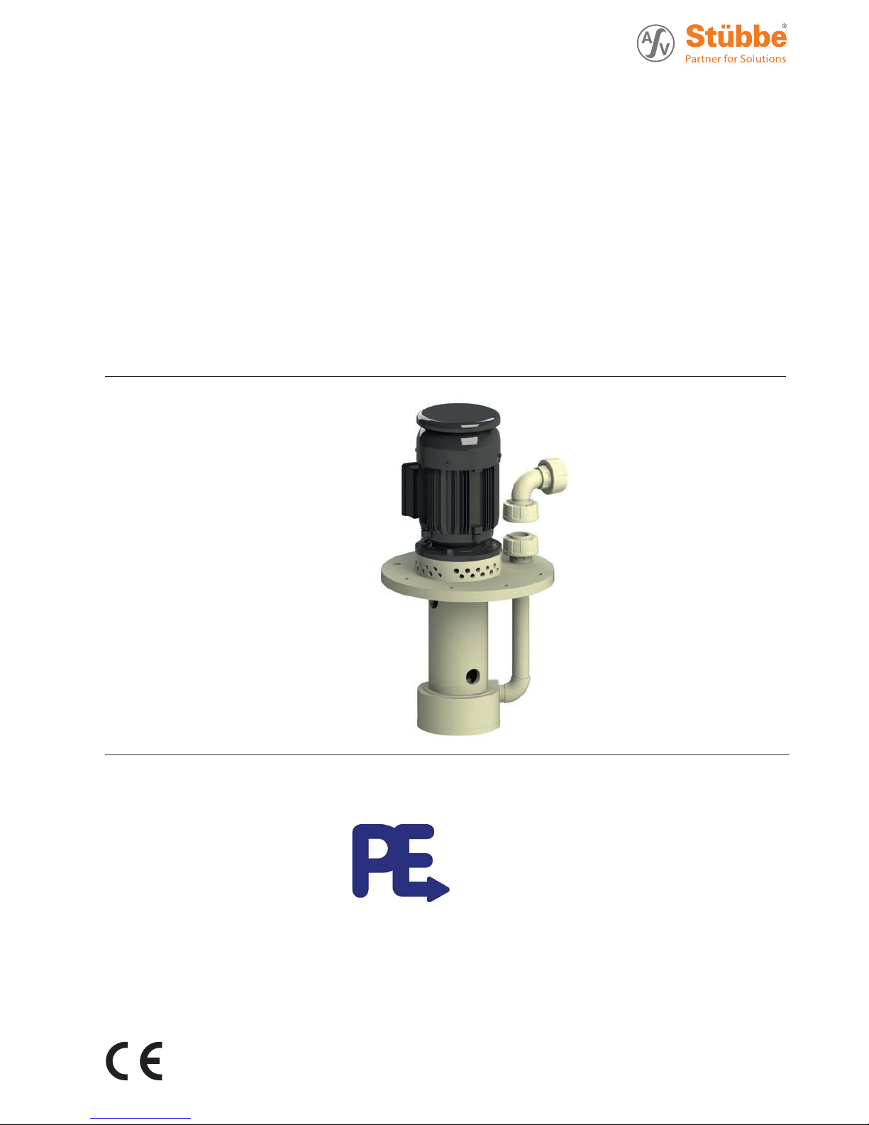
Plastic
Sump Pump
Original operating manual Series
ETLB-S
ETLB-ST
Version BA-2018.01.25 EN
Print-No. 301 356
TR MA DE Rev001
Subject to technical modi¿cations.
Read carefully before use.
Save for future use.
Distributed in the UK by.....
Pump Engineering Limited.Unit B1, Riverside Industrial Estate,
Littlehampton, West Sussex, BN17 5DF, United Kingdom
Tel: 01903 730900 Fax: 01903 730234
email: sales@pumpeng.co.uk Web: www.pumpeng.co.uk
Page 2

Table of contents
Table of contents
1 About this document ............................... 4
1.1 Target groups ............................... .. 4
1.2 Other applicable documents ................ 4
1.3 Warnings and symbols ....................... 5
2 Safety .................... ............................. 6
2.1 Intended use .................................. 6
2.2 General safety instructions .................. 6
2.2.1 Product safety .............. .................. 6
2.2.2 Obligations of the operating company . .. .. . 7
2.2.3 Obligations of personnel ........ ............. 7
2.3 Speci¿c hazards .............................. 7
2.3.1 Hazardous pumped liquids .................. 7
3 Layout and function ......... ....................... 8
3.1 Marking ....................................... 8
3.1.1 Name plate ...................... ............. 8
3.2 Description .................................. .. 8
3.3 Assembly ..... ................................ 8
4 Transport, storage and disposal .................. 9
4.1 Transport . ..................................... 9
4.1.1 Unpacking and inspection on delivery ...... 9
4.1.2 Lifting .... ..................................... 9
4.2 Storage .................. ..................... 10
4.3 Disposal ................ ....................... 10
5 Setup and connection .............................. 11
5.1 Preparing for installation .................... 11
5.1.1 Checking the operating conditions for the
ETLB-S ....................................... 11
5.1.2 Checking the operating conditions for the
ETLB-ST ...................................... 11
5.1.3 Preparing the installation site ............... 12
5.1.4 Surface preparation .......................... 12
5.2 Setting up .............................. ....... 12
5.3 Planning pipelines ............................ 12
5.3.1 Specifying supports and Àange
connections ................................... 12
5.3.2 Specifying nominal widths ................... 12
5.3.3 Optimizing changes of cross section and
direction ..................................... .. 12
5.3.4 Providing sa fety and control devices
(recommended) ............... ............... 12
5.4 Fitting the accessory part ............. ....... 13
5.4.1 Preparing the accessory part ................ 13
5.4.2 Checking the operating conditions for the
accessory part ...... .......................... 13
5.4.3 Fitting the accessory part .................... 13
5.5 Connecting the pipes ......... ............... 14
5.5.1 Keeping the piping clean .................... 14
5.5.2 Installing the pressure pipe ..... ............. 14
5.5.3 Inspection for stress-free pipe
connections ................................... 14
5.6 Electrical connection ....... .................. 15
5.6.1 Connecting the motor ........................ 15
5.6.2 Connecting the thermistor ................... 15
5.6.3 Check direction of rotation ................. .. 15
5.7 Performing the hydrostatic test .............. 15
6Operation ............... ............................. 16
6.1 Preparing for commissioning ................ 16
6.1.1 Check downtimes ............................ 16
6.1.2 Filling and bleeding .......................... 16
6.2 Commissioning ............................... 16
6.2.1 Switching on ........ .......................... 16
6.2.2 Switching off .............................. .... 17
6.3 Shutting down the pump ........ ............. 17
6.4 Restoring the pump to service .... .......... 18
6.5 Operating the stand-by pump ............... 18
7 Maintenance .................. ....................... 19
7.1 Inspections . .................................. 19
7.2 Servicing ...................................... 19
7.2.1 Maintenance in accordance with maintenance
schedule ...................................... 19
7.2.2 Cleaning the pump ......... .................. 19
7.3 Dismounting .................................. 20
7.3.1 Preparations for dismounting ................ 20
7.3.2 Disassembly of spiral casing ................ 21
7.4 Replacement parts and return .............. 21
7.5 Installing ................. ..................... 22
8Troubleshooting ................................ .... 23
9Appendix............................................. 25
9.1 Replacement parts ........................... 25
9.1.1 Part numbers and designations . . . . . . . . . . . . . 25
9.1.2 Sectional drawings ........................... 26
9.2 Technical speci¿cations ...................... 31
9.2.1 Ambient conditions ................. .......... 31
9.2.2 Sole plate tightening torques . . . . . . . . . . . . . . . . 31
9.2.3 Tightening torques of casing screws . . . . . . . . 31
9.2.4 Filling heights and installation
dimensions .................... ............... 31
9.2.5 Flange tightening torques ...... ............. 31
9.2.6 Permissible forces at the pressure
socket ......... ................................ 31
9.2.7 Sound pressure level ...... .................. 32
9.3 Maintenance schedule ....................... 32
9.4 Declaration of conformity in accor
dance with
EC machinery directive ...................... 33
2 ETLB-S, ETLB-ST BA-2018.01.25 EN 301 356
Page 3

Table of contents
List of ¿gures
Fig. 1 Name plate (example) ....................... 8
Fig. 2 Assembly .......................... ........... 8
Fig. 3 Attaching lifting gear to the pump unit ...... 9
Fig. 4 Mounting the ETLB-S pump on containers
(example with suction extension) ........... 11
Fig. 5 Mount the ETLB-ST pump on a supporting
structure ........... ........................... 11
Fig. 6 Installation of accessory parts ............... 13
Fig. 7 Sectional view 1 ...... ........................ 26
Fig. 8 Sectional view 2 ...... ........................ 26
Fig. 9 Exploded drawing ............ ................ 26
Fig. 10 Sectional view 1 ...... ........................ 27
Fig. 11 Sectional view 2 .............................. 27
Fig. 12 Exploded drawing ............ ................ 27
Fig. 13 Sectional view 1 ...... ........................ 28
Fig. 14 Sectional view 2 ...... ........................ 28
Fig. 15 Exploded drawing ............ ................ 28
Fig. 16 Sectional view 1 ...... ........................ 29
Fig. 17 Sectional view 2 ...... ........................ 29
Fig. 18 Exploded drawing ............ ................ 29
Fig. 19 Sectional view 1 ...... ........................ 30
Fig. 20 Sectional view 2 ...... ........................ 30
Fig. 21 Exploded drawing ............ ................ 30
Fig. 22 Permissible forces at the pressure
socket ........ ................................. 31
List of tables
Tab. 1 Other application documents, purpose and
where found ..................... ............. 4
Tab. 2 Warnings and symbols . ...................... 5
Tab.3 Measurestobetakenifthepumpisshut
down ............ .............................. 17
Tab. 4 Measures depending on the behavior of the
pumped liquid ................................ 17
Tab. 5 Fault/number assignment ................... 23
Tab. 6 Troubleshooting list .... ...................... 24
Tab. 7 Designation of co mponents according to part
numbers ... ................................... 25
Tab. 8 Ambient conditions ........................... 31
Tab. 9 Sole plate tightening torques ................ 31
Tab. 10 Tightening torques of casing screws . . . . . . . . 31
Tab. 11 Tightening torques ........................... 31
Tab. 12 Noise level LpA to DIN EN ISO 11203 .. . . . . 32
Tab. 13 Maintenance schedule ............ ........... 32
301 356 BA-2018.01.25 EN ETLB-S, ETLB-ST 3
Page 4

About this document
1 About this document
This manual:
• is part of the equipment
• applies to all series referred to
• describes safe and proper operation during all operating
phases
1.1 Target gro ups
Operating company
• Responsibilities:
– Always keep this manual accessible where the d evice
is used on the system.
– Ensure that employees read and observe this docu-
ment, particularly the safety instructions and warnings,
and the docume nts which also apply.
– Observe any additional country-speci¿c rules and reg-
ulations that relate to the system.
Quali¿ed personnel, ¿tter
• Mechanics quali¿cation:
–Quali¿ed employees with additional training for ¿tting
therespectivepipework
• Electrical quali¿cation:
–Quali¿ed electrician
• Transport quali¿cation:
–Quali¿ed transport specialist
• Responsibility:
– Read, observe and follow this manual and the other
applicable documents, especially all safety instructions
and warnings.
1.2 Other applicable documents
To download:
Resistance lists
Resistance of materials used to
chemicals
www.asv-stuebbe.de/pdf_resistance/300051.pdf
To download:
Data sheet
Technical data and conditions of
operation
www.asv-stuebbe.de/pdf_datasheets/300209.pdf
To download:
CE declaration of conformity
Conformity with standards
www.asv-stuebbe.de/pdf_DOC/300145.pdf
Supplier documentation
• Technical documentation for parts
supplied by subcontractors
Documentation
included
Tab. 1 Other application documents, purpose
and where found
4 ETLB-S, ETLB-ST BA-2018.01.25 EN 301 356
Page 5
About this document
1.3 Warnings and symbols
Symbol
Meaning
• Immediate acute risk
• Death, serious bodily harm
• Potentially acute risk
• Death, serious bodily harm
• Potentially hazardous situation
• Minor injury
• Potentially hazardous situation
• Material damage
Safety warning sign
Take note of all information
highlighted by the safety warning
sign and follow the instructions to
avoid injury or death.
Instruction
1., 2., ... Multiple-step instructions
9
Precondition
ĺ
Cross reference
Information, notes
Tab. 2 Warnings and symbols
301 356 BA-2018.01.25 EN ETLB-S, ETLB-ST 5
Page 6

Safety
2 Safety
The manufacturer accepts no liability for damage caused
by disregarding any of the documentation.
2.1 Intended use
• Only use the pump with suitable media (ĺ resistance lists).
• When using the pumps for solid particles, agree use in
advance with the manufacturer.
• Do not use pump for combustible or explosive Àuids.
• Adhere to the operating limits and size-dependent minimum Àow rates.
• Avoid cavitation:
– Open the suction-side ¿tting and do not use it to regu-
late the Àow.
– Do not open the pressure-side ¿tting beyond the
agreed operating point.
• Avoid overheating:
– Do not operate the pump while the pressure-side ¿tting
is closed.
• Avoid damage to the motor:
– Do not open the pressure-side ¿tting beyond the
agreed operating point.
– Note the maximum permissible number of times the
motor can be switched on per hour (ĺ manufacturer's
speci¿cations).
• Only use the pump as part of large systems/tools.
• Consult with the manufacturer regarding any other use of
the device.
Prevention of obvious misuse (examples)
• Observe pump limits of use regarding temperature, pressure, Àow and speed (ĺ data sheet).
• The power consumption of the pump increases as the speci¿c gravity of the pumped Àuid increases. Adhere to th
e
permissible speci¿c gravity in ord er to eliminate th
epos-
sibility that the pump, coupling and motor become o
verloaded (ĺ data sheet).
A lo wer speci¿c gravity is permissible. Adapt
the auxiliary
systems accordingly.
• Pumps used with water as the pumped liquid must not be
used for foodstuffs o r drinking water. Use for food or drinking water only if speci¿ed in the data sheet.
• The type of installation should be selected only in accordance with these operating instructions. For example, the
following are not allowed:
– Hanging base plate pumps in the p ipe
– Overhead installation
– Installation in the immediate vicinity of extreme heat or
cold sources
– Installation too close to a wall
2.2 General safety instructions
Observe the following regulations before carrying out any
work.
2.2.1 Product safety
The pump has been built according to state-of-the-art technology and the recognized technical safety regulations. Nevertheless, operation of the pump can still put the life and health
of the user or third parties at risk or damage the pump or other
property.
• Operate the pump only if it is in perfect technical condition
and use it only as intended, staying aware of safety and
risks, and in adherence to the in structions in this manual.
• Keep this manual and all other applicable documents complete, legible and accessible to personnel at all times.
• Refrain from any procedures and actions that would pose
a risk to personnel or third parties.
• In the event of any safety-relevant faults, shut down the
pump immediately and have the fault corrected b y appropriate personnel.
• In addition to the entire documentation for the product,
comply with statutory or other safety and accident-prevention regulations and the applicable standards and guidelines in the country where the pump is operated.
6 ETLB-S, ETLB-ST BA-2018.01.25 EN 301 356
Page 7

Safety
2.2.2 Obligations of the operating company
Safety-conscious working
• Operate the pump only if it is in perfect technical condition
and use it only as intended, staying aware of safety and
risks, and in adherence to the instructions in this manual.
• Ensure that the following safety aspects are observed and
monitored:
– Intended use
– Statutory or other safety and accident-prevention reg-
ulations
– Safety regulations governing the handling of haz-
ardous substances
– Applicable standards and guidelines in the country
where the pump is operated
– Applicable guidelines of the operator
• Make personal protective equipment available.
Quali¿ed personnel
• Make sure a ll personnel tasked with work on the pump
have read and understood this manual and all other applicable documents, espe c ially the safety, maintenance and
repair informatio n, before they start any work.
• Organize res ponsibilities, areas of competence and the
supervision of personnel.
• Ensure that all work is carried out by specialist technicians
only:
– Installation, repair and maintenance work
– Transportation
– Work on the electrical system
• Make sure that trainee personnel only work on the pump
under supervision of specialist technician s.
Safety equipment
• Provide the following safety equipment and verify its functionality:
– For hot, cold and moving parts: pump safety guarding
provided by the customer
– For pumps without capability to run dry: Dry run pro-
tection
– For potential electrostatic charging: provide suitable
grounding
Warranty
• Obtain the manufacturer's approval prior to carrying out
any modi¿cations, repairs or alterations during the warranty
period.
• Only use genuine parts or parts that have been approved
by the manufacturer.
2.2.3 Obligations of personnel
• All directions given on the pump must be followed (and kept
legible), e.g. the arrow indicating the sense of rotation and
the markings for Àuid connections.
• Pump, coupling guard a nd com ponents:
– Do not step on them or use as a climbing aid
– Do not use them to support boards, ramps or beams
– Donotusethemasa¿xing point for winches or sup-
ports
– Do not use them for storing paper or similar materials
– Do not use the hot pump or motor components as a
heating point
– Do not de-ice the pump using gas burners or similar
tools
• Do not remove the safety guarding for hot, cold or moving
parts during operation.
• Use personal protective equipment if necessary.
• Only carry out work on the pump while it is not running.
• Before all installation and maintenance work, disconnect
the motor from the mains and secure it against being
switched back on again.
• Never reach into the suction or discharge Àange.
• Following all work on the pump, re¿t safety devices in
accordance with the instructions and bring into service.
• Do not make any modi¿cations to the device.
2.3 Speci¿chazards
2.3.1 Hazardous pumped liquids
• When handling hazardous Àuids, observe the safety regulations for the handling of hazardous substances.
• Use personal protective equipment when carrying out any
work on the pump.
• Collect leaking pumped liquid and residues in a safe manner and damage them in accordance with environmental
regulations.
301 356 BA-2018.01.25 EN ETLB-S, ETLB-ST 7
Page 8
Layout and function
3 Layout and function
3.1 Marking
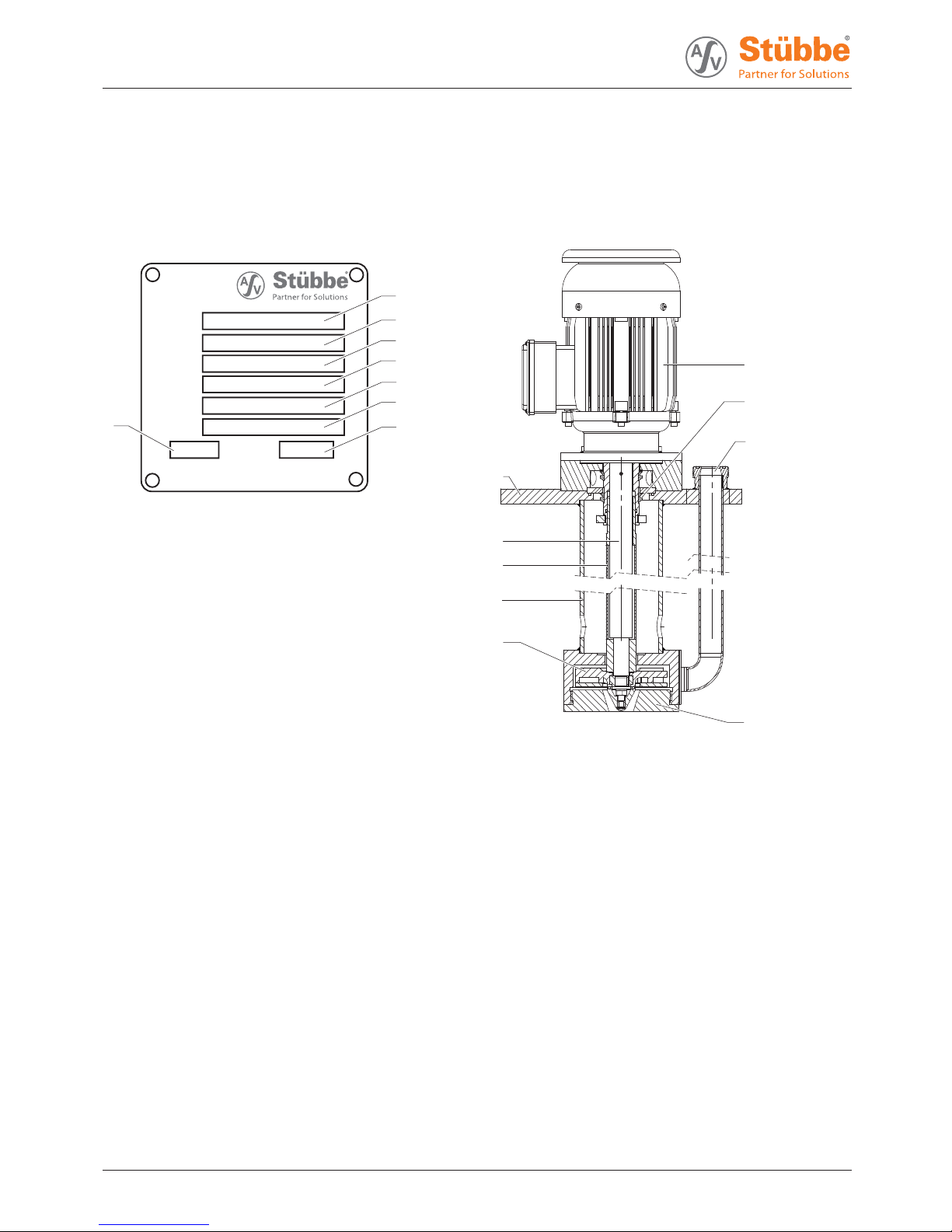
3.1.1 Name plate
Typ:
Ser. NO.:
ID. NO.:
M. Seal:
Imp. Ø:
m
3
/h
H:
m
Q:
Mat.:
Hollwieser Str. 5
D-32602 Vlotho
1
2
3
4
5
6
8
7
Fig. 1 Name plate (example)
1Pumptype
2 Serial number
3 Ident. number
4 Housing / sealing material
5 Shaft seal information
6 Impeller diameter [mm]
7 Differential head
8Flow
3.2 Description
Non self-priming, vertical centrifugal pump in modular design .
Useinopenorclosedunpressuredcontainersorpits/trenches.
The pump is dry-running safe.
3.3 Assembly
1
9
8
7
6
5
2
3
4
Fig. 2 Assembly
1 Motor
2 V-ring
3 Discharge Àange
4 Volute casing
5Impeller
6 Immersion tube
7Protectiontube
8Shaft
9Soleplate
8 ETLB-S, ETLB-ST BA-2018.01.25 EN 301 356
Page 9
Transport, storage and disposal
4 Transport, storage and disposal
4.1 Transport
The user/owner is responsible for the transport of the
pump.
Weight speci¿cations (ĺ documents for the particular
order)
4.1.1 Unpacking a nd inspection on delivery
1. Unpack the pump/pump assembly upon delivery and
inspect it for transport damage.
2. Check completeness and accuracy of delivery.
3. Ensure that the information on the name plate agrees with
the order/design data.
4. Report any transportation damage to the manufacturer
immediately.
5. Dispose of packaging material according to loc al regulations.
Retain the transport frame for horizontal storage (recommended).
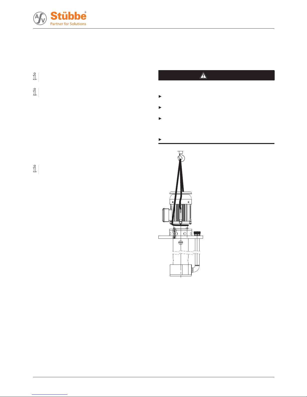
4.1.2 Lifting
DANGER
Death or limbs crushed as a result transported items
falling over!
Use lifting gear appropriate for the total weight to be transported.
Attach lifting gear in accordance with the following diagrams.
Never u se the lifting eye of the motor as the attachment
point for lifting the entire pump (the lifting eye of the motor
may be used f or securing a pump assembly with a high
center of gravity against being knocked over).
Do not stand under suspended loads.
Fig. 3 Attaching lifting gear to the pump unit
1. Attach lifting gear in accordance with the above diagram.
2. Lift the pump/pump assembly appropriately.
301 356 BA-2018.01.25 EN ETLB-S, ETLB-ST 9
Page 10

Transport, storage and d isposal
4.2 Storage
DANGER
Death or limbs crushed as a result of the pump overturning!
For vertical storage:
– Place pump on a horizontal underground and secure
against overturning.
NOTE
Material damage due to inappropriate storage!
Store the pump properly.
1. Seal all open ings with blind Àanges, blind plugs or plastic
covers.
2. Make sure the storage room meets the following conditions:
–Dry
– Frost-free
– Vibration-free
–UVprotected
3. For horizontal storage:
– Protect pump against sagging by means of proper sup-
port.
4. Rotate the pump shaft twice a month.
5. Make sure the shaft and bearing change their rotational
position in the process.
4.3 Disposal
Plastic parts can be contaminated by poisonous or radioactive pumpe d liquids to such an extent tha t cleaning will be
insuf¿cient.
WARNING
Risk of poisoning and environmental damage by the
pumped liquid or oil!
Use person al protective equipment when carrying out any
work on the pump.
Prior to the disposal of the pump:
– Collect and damage any escaping pumped liquid or oil
in accordance with local regulations.
– Neutralize residues of pumped liquid in the pump.
Remove plastic parts and damage them in accordance with
local regulations.
Dispose of the pump in accordance with local regulations.
10 ETLB-S, ETLB-ST BA-2018.01.25 EN 301 356
Page 11

Setup and connection
5 Setup and connection
NOTE
Material damage due to distortion or passage of electrical
current in the bearing!
Do not make any structural modi¿cations to the pump
assembly or pump casing.
Do not carry out any welding work on the pump assembly
or pump casing.
NOTE
Material damage caused by dirt!
Do not remove the transport seals until immediately before
installing the pump.
Do not remove any covers or transport and sealing covers
until immediately before connecting the pipes to the pump.
5.1 Preparing for installation
5.1.1 Checking the operating conditions for the ETLB-S
Fig. 4 Mounting the ETLB-S pump on container
s
(example with suction extension)
1. Ensure the required operating conditions are met:
– Resistance of b ody and seal material to the m edium
(ĺ Resistance lists).
– Required ambient conditions
(ĺ 9.2.1 Amb ient conditions, Page 31).
2. Ensure necessary dimensions for tank cut-out (ĺ data
sheet).
3. Ensure safe aeration and
venting of the container in all
operating phases.
4. Ensure the required installation dimensions and ¿lling levels are satis¿ed (ĺ data sheet).
– Minimum distances
–Maximum¿lling height
–Minimum¿lling height
5.1.2 Checking the operating conditions for
the ETLB-ST
1
3
2
4
Fig. 5 Mount the ETLB-ST pump on a supporting structure
1 Process connector on the pressure side
2 Supporting structure
3 Overrun/return of rising medium in the suspension pipe
4 Suction pipe/inlet to pump
1. Ensure the required operating conditions are met:
– Resistance of b ody and seal material to the medium
(ĺ resistance lists).
– Required ambient conditions
(ĺ 9.2.1 Amb ient conditions, Page 31).
2. Provide an appropriate supporting structure with the
required dimensions for the pump support
(ĺ data sheet). Guarantee the following conditions for t
he
supporting structure:
– Level and horizontal
– Clean (no oil, dust or other impurities)
– Capable of bearing the weight of the pump assembl
y
and all operating forces
– Stability of the pump ensured
– Resonance-free
3. Ensure safe aeration and venting of the container in all
operating phases.
4. Ensure the required installation dimensions and ¿lling levels are satis¿ed (ĺ data sheet).
– Minimum distances
–Maximum¿lling height
–Minimum¿lling height
5. Clean containers, basins or pits carefully and protect from
further contamination, e.g. by installing an overÀow containment wall in front of the container or pit inlet.
301 356 BA-2018.01.25 EN ETLB-S, ETLB-ST 11
Page 12

Setup and connection
5.1.3 Prepa ring the installation site
Ensure the installation site meets the following conditions:
– Pump is freely accessible from all sides
–Suf¿cient space for the installation/removal of the pipes
and for maintenance and repair work, especially for the
removal and installation of the pump and the motor
– Pump not exposed to external vibration (damage to
bearings)
– No corrosive exposure
– Frost protection
5.1.4 Surface preparation
Aids, tools, materials:
– Spirit level
1. Make sure the surface meets the following conditions:
– Level and horizontal
– Clean (no oil, dust or other impurities)
– Capable of bearing the weigh t of the pump assembly
and all operating forces
– Stability of the pump ensured
– Resonance-free
2. Clean containers, basins or pits carefully and protect from
further contamination, e.g. by installing overÀow wall in
front of the container or pit inlet.
5.2 Setting up
1. Remove the suction-side cover if present.
2. Lift pump/pump assembly (ĺ 4.1 Transport, Page 9 ).
3. Place pump/pump assembly on the contact surface of the
container/pit.
4. Attach sole plate to the contact surface.
– Pump must not be mechanically under stress as a
result of being attached
5. Screw on the sole plate (ĺ 9.2.2 Sole plate tightening
torques, Page 31).
5.3 Planning pipelines
Water hammer may damage the pump or the system. Plan
the pipes and ¿ttings as far as possible to prevent water
hammer occurring.
5.3.1 Specifying supports and Àange connections
NOTE
Material damage du e to excessive forces and torques on
the pump.
Ensure pipe connection without stress.
1. Plan pipes safely:
– No pulling or thrusting forces
– No bending moments
– Adjust for changes in length due to temperature
changes (compensators, expansion shanks)
– Optional installation position
2. Support pipes in front of the pump.
3. Ensure the pipe supports have permanent low-friction
properties an d do not seize up due to corrosion.
5.3.2 Specifying nominal widths
Keep the Àow resistance in the pipes as low as possible.
1. Make sure the suction extension is not smalle r than the
nominal width of the suction branch.
2. Make sure the nominal pressure line width is not smaller
than the nominal discharge Àange width.
–EnsuretheÀow velocity is less than 3 m/s.
5.3.3 Optimizing changes of cross section and
direction
1. Avoid radii of curvature of less than 1.5 times the nominal
pipe diameter.
2. Avoid abrupt changes of cross-section along the piping.
5.3.4 Providing safety and control d evices
(recommended)
Avoid reverse running
1. Install a non-return valve between the discharge Àange and
stop valve, to ensure that the medium does not Àow back
after the pump is switched off.
2. In order to enable venting, include vent connection
between discharge Àanges and non-return valve.
Make prov isions for isolating and shutting off the pipes
For maintenance and repair work.
Provide sh ut-off devices in the pressure pipe.
Allow measurements of the operating conditions
1. Provide a pressure gauge in the pressure line for pressure
measurement.
2. Provide pressure measurement on the pump side.
12 ETLB-S, ETLB-ST BA-2018.01.25 EN 301 356
Page 13

Setup and connection
5.4 Fitting the accessory part
5.4.1 Preparing the accessory part
1. Unpack the accessory part when received and inspect it for
transportation damage.
2. Report any transportation damage to the manufacturer
immediately.
3. For immediate installation, damage packaging material
according to local regulations. If installation is not to be
performed until a later time, leave the accessory part in its
original packaging.
5.4.2 Checking the operating conditions for
the accessory part
1. Ensure the necessary installation dimensions and ¿lling
level of the pump with the accessory part installed (ĺ data
sheet):
– Minimum distances
–Maximum¿lling height
–Minimum¿lling height
2. Ensure that the substrate or container can take the weight
of the pump bearing the accessory part.
5.4.3 Fittin g the accessory part
1
2
3
4
5
6
7
8
Fig. 6 Installation of accessory parts
1 Discharge elb ow / Àange adapter
2 Union nut
3 Union nut
4 Discharge Àange
5 Volute casing
6 Adapter
7 Suction strainer
8 Suction extension
301 356 BA-2018.01.25 EN ETLB-S, ETLB-ST 13
Page 14

Setup and connection
Installing a suction extension and suction strainer
If required the suction extension or the suction strainer can
be installed in the adap ter. Optionally the suction strainer
can b e installed in the suction extension.
Accessory part prepared
Operating conditions for the accessory part checked
Tool and material:
– Face wrench (125/6 AF)
1. Using the face wrench, unscrew the volute casing cover
clockwise from the volute casing (5). Note this is a left-hand
thread.
2. Using the face wrench, screw the a dapter (6) ¿nger-tight
into the left-hand thread of the volute casing (5 ). In doing
so, ensure the following:
– The sealing ring is positioned correctly
– Do not install the sealing ring dry
3. Depending on the installation situation, proceed as follows:
– When installing the suction extension (8): screw the
suction extension (8) ¿nger-tight into the adapter (6).
Note this is a right-ha nd thread.
– If necessary, screw the suction strainer (7) ¿nger-tight
into the suction extension (8).
–OR–
– When installing the suction strainer (7): screw the suc-
tion strainer (7) ¿nger-tight into the adapter (6). Note
this is a right-hand thread.
Installing the discharge elbow / Àange adapter
Accessory part prepared
Operating conditions for the accessory part checked
1. Unscrew the union nut (3) from the discharge Àange (4). If
necessary, remove the insert from the discharge Àange (4).
2. Position the discharge elbow / Àange adapter (1) on the
discharge Àange (4) and align it.
3. Using the union nuts (2), bolt the discharge elbow / Àange
adapter (1) ¿nger-tight to the discharge Àange (4).
5.5 Connecting the pipes
NOTE
Material damage du e to excessive forces and torques on
the pump.
Ensure pipe connection without stress.
5.5.1 Keeping the piping clean
NOTE
Material damage due to impurities in the pump!
Make sure no impurities can enter the pump.
1. Clean all piping parts and ¿ttings prior to assembly.
2. Flush all pipes carefully with neutral medium.
3. Ensure no Àange seals protrude inwards.
4. Remove any blind Àanges, plugs, protective foils and/or
protective paint from the Àanges.
5.5.2 Installing the pressure pipe
1. Remove the transport and sealing covers from the pump.
2. Fit the pressure line stress-free and sealed
3. Ensure no seals protrude inwards.
5.5.3 Inspe ction for stress-free pipe connections
Piping installed and cooled down
1. Disconnect the pipe connecting Àanges fro m the pump.
2. Check whether the pipes can be moved freely in all directions within the expected range of expansion:
– Nominal width < 150 mm: by hand
– Nominal width > 150 mm: with a small lever
3. Make sure the Àange surfaces are parallel.
4. Reconnect the pipe connecting Àanges to the pump.
5. If present, check support foot for stress.
14 ETLB-S, ETLB-ST BA-2018.01.25 EN 301 356
Page 15

Setup and connection
5.6 Electrical connectio n
DANGER
Risk of electrocution!
All electrical work must be carried out only by quali¿ed electricians.
Before all work on the electrical system, disconnect the
motor from the mains and secure against being switched
back on again.
5.6.1 Connecting the motor
Follow the instructions of the motor manufactu rer.
1. Connect the motor according to the connection diagram.
2. Make sure no danger arises due to electric power.
3. Install an EMERGENCY STOP switch.
5.6.2 Connecting the thermistor
2TP1
2TP2
2TP1 2TP2
Connect the PTC thermistor to the motor protector.
– Activation temperature 155°C
– Test voltage 2.5 V
5.6.3 Check direction of rotation
DANGER
Danger to life from rotating parts.
Use perso nal protective equipment when carrying out any
work on the pump.
Maintain an adequate distance from rotating parts.
1. Switch on motor for max. 2 seconds and switch it off again
immediately.
2. Check whether the sense of rotation of the motor matches
the direction of rotation on the fan impeller.
3. If the sense of rotation is different: Change over any two
phases.
5.7 Performing the hydrostatic test
Only necessary if the entire system needs to be tested
under pressure.
NOTE
Material damage due to bursting of pump casing.
Testing pressure must not exceed the permissible pump
pressure (ĺ documents for the particular order).
Make sure the testing pressure does not exceed the permissible pump pressure.
– If necessary, do not perform pressure test on the pump.
301 356 BA-2018.01.25 EN ETLB-S, ETLB-ST 15
Page 16

Operation
6Operation
6.1 Preparing for commissioning
6.1.1 Check dow ntime s
Check downtimes (ĺ 6.4 Restoring the pump to service,
Page 18).
6.1.2 Filling and bleeding
WARNING
Risk of injury and poisoning due to hazardous pumped
liquids!
Use protective equipment for any work on the pump.
Collect leaking liquid safely and damage ¿tting in accor-
dance with local regulations.
1. Close the pressure-side ¿tting.
2. Fill pump and, if present, suction pipe with Àuid.
Ensure minimum ¿lling height when doing so
3. Verify that no pipe connections are leaking.
6.2 Commissioning
6.2.1 Switching on
Pump set up and connected properly
Motor set up and connected properly
All connections stress-free and se aled
All safety equipment installed and tested for functionality
Pump prepared, ¿lled and vented correctly
Container is ¿lled suf¿ciently up to minimum height “Z”
(ĺ 9.2.4 F illing heights and in s tallation dimensions,
Page 31).
DANGER
Risk of injury due to running pump!
Do no t touch the pump when it is running.
Do not carry out any work on the pump when it is running.
Allow the pump to cool down comp letely before starting any
work.
DANGER
Risk of injury and poisoning due to pumped liquid spraying out!
Use person al protective equipment when carrying out any
work on the pump.
NOTE
Risk of cavitation if suction Àow is restricted!
Open the suction-side ¿tting and do not use it to regulate
the Àow.
Do not open the pressure-side ¿tting beyond the operating
point.
NOTE
Material damage due to overheating.
Do not operate the pump for long periods with the pressureside ¿tting closed.
Observe minimum Àow (ĺ order data sheet).
1. Open the suction-side ¿tting.
2. Close the pressure-side ¿tting.
3. Switch on the motor and check it for smooth running.
4. Once the motor has reach
ed its nominal speed, open
the pressure-side ¿tt
ing slowly until the operating point is
reached.
5. Make sure temperatur e change is smaller than 5 K/min for
pumps with hot Àuids.
6. After the initial stress due to the pressure and operating
temperature, check that the pump is not leaking.
16 ETLB-S, ETLB-ST BA-2018.01.25 EN 301 356
Page 17

Operation
6.2.2 Switching off
Pressure-side ¿tting closed (recommended)
WARNING
Risk of injury due to hot pump parts!
Use perso nal protective equipment when carrying out any
work on the pump.
1. Switch off motor.
2. Check all connecting bolts and tighten the m if necessary
(only a fter initial commissioning).
6.3 Shutting down the pump
DANGER
Risk of injury due to running pump!
Do not touch the pump when it is running.
Do not carry out any work on the pump when it is running.
Before all installation and maintenance work, disconnect
the motor from the mains and secure it against being
switched back on again.
DANGER
Risk of electrocution!
All electrical work must be carried out only by quali¿ed electricians.
Before all work on the electrical system, disconnect the
motor from the mains and secure against being switched
back on again.
WARNING
Risk of injury and poisoning due to hazardous pumped
liquids!
Use protective equipment for any work on the pump.
Collect leaking liquid safely and damage ¿tting in accor-
dance with local regulations.
Take the following measures whenever the pump is shut
down:
Pump is Action
shut down
Take measures appropriate for
the Àuid (ĺ Table 4 Measures
depending on the behavior of
the pumped liquid, Page 17).
…emptied
Close suction and pressure-side
¿tting.
…dismounted
Isolate the motor from its power
supply and secure it again st
unauthorized switch-on.
…put into
storage
Note measures for storage.
Tab. 3 Measures to be taken if the pump is shut down
Duration of shutdown (depending
on process)
Behavior of the
pumped liquid
Short
Long
Crystallized or
polymerized,
solids
sedimenting
Flush the
pump.
Flush the
pump.
Solidifying/
freezing,
non-corrosive
Heat up or
empty the
pump and
containers.
Empty the
pump and
containers.
Solidifying/
freezing,
corrosive
Heat up or
empty the
pump and
containers.
Empty the
pump and
containers.
Remains liquid,
non-corrosive
––
Remains liquid,
corrosive
–
Empty the
pump and
containers.
Tab. 4 Measures depending on the behavior
of the pumped liquid
301 356 BA-2018.01.25 EN ETLB-S, ETLB-ST 17
Page 18

Operation
6.4 Restoring the pump to service
1. Complete all steps as for commissioning
(ĺ 6.2 Commissioning, Page 16).
2. If the pump is shut down for over 1 year, replace elastomer
seals (O-rings, shaft sealing rings).
6.5 Operating the stand-by pump
Stand-by pump ¿lled and bled
Operate the stand-by pump at least once a week.
Open pressure-side ¿tting far enough so that the stand-by
pump operating temperature is achieved and heating is
even (ĺ 6.2.1 S witching on, Page 16).
18 ETLB-S, ETLB-ST BA-2018.01.25 EN 301 356
Page 19

Maintenance
7 Maintenance
Trained service technicians are available for ¿tting and
repair work. Submit evidence of conveyed medium on
request (DIN safety data sheet or safety certi¿cate).
7.1 Inspections
The inspection intervals depend on the o perational strain
on the pump.
DANGER
Risk of injury due to running pump!
Do not touch the pump when it is running.
Do not carry out any work on the pump when it is running.
WARNING
Risk of injury and poisoning due to hazardous pumped
liquids!
Use protective equipment for any work on the pump.
1. Check at appropriate intervals:
– Adherence to the m inimum Àow rate
– Normal operating conditions unchanged
– Filling level of the container
2. For trouble-free operation, always ensure the following:
–Noleaks
– No cavitation
– Free and clean ¿lters
– No unusual running noises or vibrations
– No inadmissible leaks on the shaft seal
7.2 S ervicing
Operating life of antifriction bearings in operation are within
permissible range: >2 years.
Intermittent operation, high temperatures, low viscosities
and aggressive ambient and process conditions reduce the
service life of antifriction bearings.
Plain bearings are subject to natural wear and tear which
is heavily dependent on the respective op erating conditions. It is therefore not possible to make general statements about the operating life.
DANGER
Risk of injury due to running pump!
Do not touch the pump when it is running.
Do not carry out any work on the pump when it is running.
Before all installation and maintenance work, d isconnect
the motor from the mains and secure it against being
switched back on again.
DANGER
Risk of electrocution!
All electrical work must be carried out only by quali¿ed electricians.
Before all work on the electrical system, disconnect the
motor from the mains and secure against being switched
back on again.
WARNING
Risk of injury and poisoning due to hazardous or hot Àuid!
Use protective equipment for any work on the pump.
Allow the pump to cool down co mpletely before comme
nc-
ing any work.
Make sure the pump is depressurized.
Empty the pump, safely collect the pumped liquid and dam-
age it in accordance with environmental rules and requirements.
7.2.1 Maintenance in accorda nce with maintenance schedule
Perform maintenance work in accordance with the maintenance schedule (ĺ 9.3 Maintenance schedule, Page 32).
7.2.2 Cleaning the pump
NOTE
High water pressure or spray water can damage bearings!
Do not clean bearing areas with a water or steam jet.
Clean large-sca
le grime from the pump.
301 356 BA-2018.01.25 EN ETLB-S, ETLB-ST 19
Page 20

Maintenance
7.3 Dismounting
DANGER
Risk of injury due to running pump!
Do no t touch the pump when it is running.
Do not carry out any work on the pump when it is running.
Before all installation and maintenance work, disconnect
the motor from the mains and secure it against being
switched back on again.
DANGER
Risk of electrocution!
All electrical work must be carried out only by quali¿ed electricians.
Before all work on the electrical system, disconnect the
motor from th e mains and secure against being switched
back on again.
DANGER
Death or limbs crushed as a result of the pump overturning.
Place pump on a horizontal underground and secure
against overturning.
WARNING
Risk of injury and poisoning due to hazardous or hot Àuid!
Use protective equipment for any work on the pump.
Allow the pump to cool down completely before commenc-
ing any work.
Make sure the pump is depressurized.
Empty the pump, safely collect the pumped liquid and dam-
age it in accordance with environmental rules and requirements.
WARNING
Risk of injury due to heavy components!
Pay attention to the c omponent we ight. Lift and transport
heavy components using suitable lifting gear.
Set down components safely and secure them against
overturning or rolling away.
WARNING
Risk of injury during disassemb ly!
Secure the pressure-side gate valve against accidental
opening.
Depressurize the blocking pressure system, if available.
Wear protective gloves, components can become very
sharp-edged due to wear or damage.
Remove spring-loaded components carefully (e.g.
mechanical seal, stressed bearing, valves etc.), as components can be ejected by the spring stress.
Observe the manufacturer's speci¿cations (e.g. for the
motor, coupling, mechanical seal, blocking pressure system, cardan shaft, drives, belt drive etc.).
NOTE
Material damage due to incorrect dismounting/installation
of the pump.
Only specialist mechanics should complete dismounting/
installation work.
7.3.1 Prepa rations for dismounting
Pump is depressurized
Pump completely empty, Àushed and decontaminated
Electrical connections disconnected and motor secured
against switch-on
Pump cooled down
Pressure gauge lines, pressure gauge and ¿xtures dis-
mounted
When dismounting, observe the fo llowing:
– Mark the precise orientation and position of all compo-
nents before dismounting them.
– Dismount comp onents concentrically without c anting.
– Dismount pump (ĺ sectional drawing).
20 ETLB-S, ETLB-ST BA-2018.01.25 EN 301 356
Page 21

Maintenance
7.3.2 Disassembly of spiral casing
Removal of the hydraulic system, size 15–60
1. Undo the housing cover (16 1.01) with left-hand threa d.
2. Undo the impeller cap (260.01).
3. Undo the hexagon screw (914.01).
4. Pull the impeller with shaft protection tube (230.0 1) off the
motor shaft.
Removal of the hydr aulic system, other sizes
1. Undo the housing cover (16 1.01) with left-hand threa d.
2. Undo the impeller cap (260.01).
3. Undo the nut (920.02) with circlip (934.01) and washer
(550.01).
4. Remove the impeller together with shaft protection tube
(230.01) from the motor shaft a nd keep key (940.01).
Removal of the V-rings, one sealing washer
Sizes 15-60; 20-100; 25-125S; 25-125L; 32-125; 40-125;
32-125
1. Complete steps 1- 4 of hydraulic system disassembly.
2. Undo hexagon nut (920.01) with washer (554.01).
3. Pull the suspension pipe (713.01) to the bottom.
4. Remove the centrifugal disk (558.01) if ava ilable.
5. Undo the V rings (507.01) and sealing washer (444.01).
Removal of the V-rings, two sealing washers
Sizes 32-160 5,5/7,5kW; 40-160 5,5/7,5kW; 50-125
5,5/7,5kW; 32-160 4,0kW; 40-160 4,0kW; 50-125 4,0kW;
80-200
1. Complete steps 1- 4 of hydraulic system disassembly.
2. Undo the screw (901.01) with washer (554.02).
3. Pull the suspension pipe (713.01) to the bottom.
4. Undo the hexagon screws (914.04).
5. Undo the lower sealing washer (444.01), the lower V-ring
(507.01) and the intermediate ring (509.01).
6. Pull off downwards the sealing Àange (490.01) with upper
sealing washer (444.02).
7. Undo the upp er V-ring (507.01).
7.4 R eplacement parts and return
1. Have the following information ready to hand when ordering spare parts
–Devicetype
–IDnumber
– Nominal pressure and diameter
– Connection and gasket material
2. Please complete and enclose the document of compliance
for returns
(ĺ w ww.asv-stuebbe.de/pdf_DOC/300359.pdf).
301 356 BA-2018.01.25 EN ETLB-S, ETLB-ST 21
Page 22

Maintenance
7.5 Installing
Install components concentrically and without tilting in
accordance with the m arkings applied.
WARNING
Risk of injury due to heavy components!
Pay attention to the c omponent we ight. Lift and transport
heavy components using suitable lifting gear.
Set down components safely and secure them against
overturning or rolling away.
WARNING
Risk of injury during assembly!
Install spring-loaded components carefully (e.g. mechanical seal, stressed bearing, valves etc.), as components can
be ejected by the spring stress.
Observe the manufacturer's speci¿cations (e.g. for the
motor, coupling, mechanical seal, blocking pressure system, cardan shaft, drives, belt drive etc.).
NOTE
Material damage due to incorrect dismounting/installation
of the pump.
Only specialist mechanics should complete dismounting/
installation work.
NOTE
Material damage due to unsuitable components!
Always replace lost or damaged screws with screws of the
same strength where required.
Only replace seals with seals of the same material.
NOTE
Material damage, fragile components.
Install ceramic parts of the plain bearing and magnets of the
magnetic coupling with care, do not strike them or knock
them.
1. When in stalling please obser
ve:
– Replace worn parts with gen
uine spare parts.
– Replace seals, inserting
them in such a way that they
are unable to rotate.
–Donot
apply synthetic or mineral oil, grease or cleaning
agen
ts to elastomer components.
–Ad
here to the prescribed tightening torques
(
ĺ 9.2.3 Tightening torques of casing screws,
Page 31).
2. Installing the pump:
– in reverse order to the dismounting
(ĺ 7.3 Dismounting, Page 20).
– ĺ sectional drawing
3. Installing the pump in the system (ĺ 5 Setup and connec-
tion, Page 11).
22 ETLB-S, ETLB-ST BA-2018.01.25 EN 301 356
Page 23

Troubleshooting
8 Troubleshooting
If faults occur which are not speci¿ed in the following table or
cannot be traced back to the sp eci¿ed causes, please consult
the manufacturer.
Possible faults are identi¿ed by a fault number in the table
below. This number identi¿es the respective cause and remedy in the troubleshooting list.
Fault Number
Pump not pumping 1
Pumpingrateinsuf¿cient
2
Pumping rate excessive 3
Pumping pressure insuf¿cient
4
Pumping pressure excessive
5
Pump running roughly 6
Pump leaks
7
Excessive motor power uptake 8
Tab. 5 Fault/number assignment
Fault number
12 3456
7
8
Cause
Remedy
X
–––––––
Pressure pipe close d by ¿tting
Open the ¿tting.
XX–X
–
X
––
Pump or suction strainer blocked or
encrusted
Clean intake/suction pipe, pump or
suction strainer.
X
–––––––
Transport and sealing cover still in place Remove the transport and sealing cover.
—
X
—
X
—
X
——
Back pressure of the system is too high,
pump selected is too small.
Consult the manufacturer.
–
X
–
X
–
X
––
Suction head too large: NPSH
pump
is larger
than NPSH
system
Increase pump inlet pressure.
Consult the manufacture
r.
X
––––X––
Intake/suction pipe and pump not correctly
vented or not completely ¿lled
Completely ¿ll and vent pump and/or
pipe.
XX–X
–
X
––
Air is sucked in
Check the ¿lling level of the containe r.
XX–X
–
X
––
Proportion of gas too high: pump is
cavitating
Consult the manufacturer.
–
X
–
X
–
X
––
Temperature of Àuid is too high: pump is
cavitating
Increase pump inlet pressure.
Lower temperature.
Contact the manufacturer.
–
X
–
X
–––
X
Viscosity or speci¿c gravity of the pumped
liquid outside the range speci¿ed for the
pump
Consult the manufacturer.
XX–X
––––
Geodetic differential head and/or pipe Àow
resistances too high
Remove sediments from the pump
and/or pressure pipe.
Install a larger impeller and consult the
manufacturer.
–
X
––
XX
––
Pressure-side ¿tting not opened wide
enough
Open the pressure-side ¿tting.
XX
––
XX
––
Pressure pipe blocked
Clean the pressure pipe.
301 356 BA-2018.01.25 EN ETLB-S, ETLB-ST 23
Page 24

Troubleshooting
Fault number
12 3456
7
8
Cause
Remedy
XX–X
–
X
––
Pump runnin g in the wrong direction
Check s ense of rotation and correct it if
necessary (ĺ 5.6.3 Check d irection of
rotation, Page 15).
XX–X
––––
Motor speed too low
Compare the required motor speed with
the speci¿cations on the pump type
plate. Replace the motor if necessary.
Increase the motor speed if speed
control is available.
–
X
–
X
–
X
––
Pump parts worn
Replace the worn pump parts.
––
XX–X
–
X
Pressure-side ¿tting opened too wide
Throttle down at the pressure-side ¿tting.
Machine the impeller down. Consult the
manufacturer and adjust the impeller
diameter.
––X––X–
X
Geodetic di fferential head, pipe Àow
resistances and/or other resistances lower
than speci¿ed
Throttle down the Àow rate at the
pressure-side ¿tting. Observe the
minimum Àow rate.
Machine the impeller down. Consult the
manufacturer and adjust the impeller
diameter.
––X–
X
–––
Viscosity lower than expected
Machine the impeller down. Consult the
manufacturer and adjust the impeller
diameter.
––X–
XX–X Motor speed too high
Compare the required motor speed with
the speci¿cations on the pump type
plate. Replace the motor if necessary.
Reduce the motor speed if speed control
is available.
––X–
XX–X Impeller diameter too large
Throttle down the Àow rate at the
pressure-side ¿tting. Observe the
minimum Àow rate.
Machine the impeller down. Consult the
manufacturer and adjust the impeller
diameter.
XX–X
–
X
––
I
mpeller out of balance or blocked
C
lean the impeller.
–
X
–
X
–
X
––
Hydraulic parts of the pump dirty, clotted or
encrusted
Dismount the pump.
Clean the parts.
–– –– –X–
X
Defective antifriction bearing in motor
Replace the antifriction bearing
(ĺ manufacturer's speci¿cations).
–– –– – –X–
Connecting bolts not correctly tightened
Tighten the connecting bolts.
–– –– – –X–
Faulty housing seal
Replace the housing seal
–– –– –
X X X Pump distorted
Check the pipe connections and pump
attachment.
–
X
–
X
–
X
–
X Motor running on 2 phases
Check the fuse and replace it if
necessary.
Check the cable connections and
insulation.
Tab. 6 Troubleshooting list
24 ETLB-S, ETLB-ST BA-2018.01.25 EN 301 356
Page 25

Appendix
9 Appendix
9.1 Replacement parts
9.1.1 Part numbers and designations
Part no. Designation
161.01
1)
Housing cover
230.01 Impeller
260.01 Impeller cap
412.01
O-ring (sealing washer)
412.02
O-ring (shaft sleeve)
412.03
O-ring (impeller cap)
412.04
O-ring (connection)
412.05
O-ring (sealing washer)
444.01
Sealing washer
444.02
Sealing washer
490.01
Sealing Àange
490.02
Wafer type Àange
507.01
Splash ring (shaft sleeve)
509.01
Intermediate ring (sealing washer)
523.01
Shaft sleeve
531.01
Spring dowel sleeve (shaft sleeve)
550.01 Impeller washer
554.01
Washer (motor attachment)
554.02
Washer (Àange attachment)
554.03
Washer (sealing washer)
558.01
Centrifugal disk (shaft sleeve)
713.01
Suspension pipe
730.01
Pipe connector (insert)
731.01
Pipe joint (gland nut)
801.01 Flange motor
901.01
Hexagonal screw (Àange attachment)
902.01
Stud screw (motor attachment)
914.01 Hexagon socket-head screw
(cylinder screw) (impeller)
914.02 Hexagon socket-head screw
(cylinder screw) (motor attachment)
914.03 Hexagon socket-head screw
(cylinder screw) (sealing washer)
914.04 Hexagon socket-head screw
(cylinder screw) (intermediate Àange)
920.01
Nut (motor attachment)
Part no. Designation
920.02
Nut (impeller)
934.01
Circlip (impeller)
940.01
Fitted key (impeller)
Tab. 7 Designation of components according
to part numbers
1) Not suitable for suction strainer or suction extension
301 356 BA-2018.01.25 EN ETLB-S, ETLB-ST 25
Page 26

Appendix
9.1.2 Sectional drawings
Size 15-60
801.01
531.01
507.01
412.01
507.01
412.02
713.01
412.03
914.01
260.01
161.01
230.01
444.01
523.01
490.01
412.04
731.01
730.01
Fig. 7 Sectional view 1
920.01
554.01
902.01
Fig. 8 Sectional view 2
161.01
230.01
260.01
412.03
412.02
730.01
731.01
412.04
444.01
531.01
523.01
507.01
490.01
801.01
914.01
713.01
902.01
554.01
920.01
412.01
507.01
Fig. 9 Exploded drawing
26 ETLB-S, ETLB-ST BA-2018.01.25 EN 301 356
Page 27

Appendix
Sizes 20-100; 25-125S; 25-125L
801.01
531.01
507.01
412.01
507.01
412.02
412.03
260.01
161.01
230.01
444.01
523.01
490.01
412.04
550.01
934.01
920.02
731.01
730.01
Fig. 10 Sectional view 1
920.01
554.01
902.01
713.01
Fig. 11 Sectional view 2
801.01
507.01
444.01
412.01
490.01
523.01
507.01
412.02
531.01
558.01
731.01
730.01
412.04
920.02
260.01
161.01
934.01
412.03
230.01
550.01
940.01
902.01
554.01
713.01
920.01
Fig. 12 Exploded drawing
301 356 BA-2018.01.25 EN ETLB-S, ETLB-ST 27
Page 28

Appendix
Sizes 32-125; 40-125
412.04
801.01
531.01
507.01
444.01
412.01
490.01
507.01
523.01
412.02
230.01
412.03
161.01
260.01
550.01
920.02 934.01
731.01
730.01
Fig. 13 Sectional view 1
920.01
554.01
902.01
713.01
Fig. 14 Sectional view 2
801.01
490.01
507.01
523.01
444.01
412.02
507.01
731.01
730.01
412.04
230.01
412.03
260.01
161.01
531.01
920.02
934.01
550.01
940.01
713.01
902.01
554.01
920.01
412.01
Fig. 15 Exploded drawing
28 ETLB-S, ETLB-ST BA-2018.01.25 EN 301 356
Page 29

Appendix
Sizes 32 - 160 4kW; 40-160 4kW; 50-125 4kW
412.04
801.01
531.01
507.01
444.02
412.01
490.01
507.01
523.01
412.02
230.01
412.03
161.01
260.01
550.01
920.02 934.01
490.02
444.01
509.01
731.01
730.01
412.05
Fig. 16 Sectional view 1
920.01
554.03
914.03
713.01
554.01
554.02
901.01
914.04
Fig. 17 Sectional view 2
801.01
507.01
490.02
523.01
531.01
444.01
507.01
731.01
730.01
412.04
230.01
412.03
260.01
161.01
412.01
920.01
554.01
713.01
940.01
550.01
934.01
920.02
914.04
490.01
554.02
901.01
444.02
412.05
412.05
509.01
914.03
554.03
412.02
Fig. 18 Exploded drawing
301 356 BA-2018.01.25 EN ETLB-S, ETLB-ST 29
Page 30

Appendix
Sizes 32-160 5.5 / 7.7 kW; 40-160 5.5 / 7.7 kW;
50-125 5.5 / 7.7 kW; 80-200
412.04
801.01
531.01
507.01
444.02
412.01
490.01
507.01
523.01
412.02
230.01
412.03
161.01
260.01
550.01
920.02 934.01
490.02
444.01
509.01
731.01
730.01
412.05
Fig. 19 Sectional view 1
920.01
554.03
914.03
713.01
554.01
554.02
901.01
914.02
914.04
Fig. 20 Sectional view 2
801.01
507.01
490.02
523.01
531.01
444.01
507.01
731.01
730.01
412.04
230.01
412.03
260.01
161.01
412.01
920.01
554.01
713.01
940.01
550.01
934.01
920.02
914.02
490.01
554.02
901.01
444.02
412.05
412.05
509.01
914.03
554.03
412.02
914.04
Fig. 21 Exploded drawing
30 ETLB-S, ETLB-ST BA-2018.01.25 EN 301 356
Page 31

Appendix
9.2 Technical speci¿cations
Further technical data (ĺ data sheet).
9.2.1 Ambient conditions
Operation under any other ambient conditions should be
agreed with the manufacturer.
Relative humidity [%]
Tem per ature [°C]
Long-term
Short-term
Installation
height
above sea
level [m]
–20 to +40
1)
85 100 1000
Tab. 8 Ambient conditions
1) material-dependent
9.2.2 Sole plate tightening torques
Screw
Md [Nm]
Screw
Md [Nm]
M8
7
M16 63
M10 14 M20 113
M12 24 M24 193
Tab. 9 Sole plate tightening torques
9.2.3 Tightening torques of casing screws
Apply graphite paste to metallic connections prior to
assembly.
Size Metal /
metal
1)
Metal /
plastic
2)
Metal in
metal
inserts /
plastic
3)
M6 9 6
5
M8 21
7
6
M10421410
M12732425
M16 170 63 30
M20 340 113 32
M24 580 193 34
Tab. 10 Tightening torques of casing screws
1) Metal: Screws, nuts, housing, pipes
2) Metal: screws, nuts / Plastic: housing, pipes
3) Metal: screws in metal inserts / Plastic: housing with
screwed in or encapsulated metal inserts
9.2.4 Filling heights and installation dimensions
Filling heights and installation dimensions (ĺ data sheet).
9.2.5 Flange tightening torques
Tightening torque
*1)
MD [Nm]
for the variants
d
[mm]ND[mm]
Flat sealing
ring
max. 10 bar
max. 40 °C
Pro¿le seal
max. 16 bar
O-ring
max. 16 bar
20 15 10 10 10
25 20 12 12 12
32 25 15 12 12
40 32 20 15 15
50 40 25 15 15
63 50 30 20 20
75
65 35 20 20
90 80 35 20 20
Tab. 11 Tightening torques
1) Use a torque wrench
9.2.6 Permissible forces at the pressure socket
Fig. 22 Permissible forces at the pressure socket
ȈFx = 0
ȈFy = 0
ȈFz = 0
301 356 BA-2018.01.25 EN ETLB-S, ETLB-ST 31
Page 32

Appendix
9.2.7 Sound p ressure level
Maximum noise level LpA for 2-terminal 50Hz/60Hz motors, in
dB(A)
Motor power
rating
0.37 kW 0.55 kW 0.7 5 kW 1.10 kW 1.50 kW 2.20 kW 3.00 kW 4.00 kW 5.50 kW 7.50 kW
Frequency 50Hz60Hz50Hz60Hz50Hz60Hz50Hz60Hz50Hz60Hz50Hz60Hz50Hz60Hz50Hz60Hz50Hz60Hz50Hz60
Hz
ETLB-S 15–60
59 61 59 61 61 63
ETLB-S 20–100
59 61 59 61 61 63
ETLB-S
125–125S
59 61 59 61 61 63 61 63 65 67 65 67
ETLB-S
125–125L
61 63 61 63 65 67 65 67
ETLB-S 32–125
65 67 65 67 68 70 70 72 70 72
ETLB-S 32–160
70 72 70 72 70
ETLB-S 40–125
65 65 67 68 70 70 72 70 72 70
ETLB-S 40–160
70 70 72 70
ETLB-S 50–125
70 70 72 70
ETLB-S
80–200
1)
66 68 66
Tab. 12 Noise level LpA to DIN EN ISO 11203
1) 4-wire
Measuring conditions:
• Distance to the pump: 1 m
• Operation: free of cavitation
• Motor: IEC standard motor
• Tolerance ±3 dB
9.3 Maintenance schedule
Designation Interval Maintenance
Operating
temperatures
weekly
Check storage
temperature.
Check motor temperature.
Undoable
screwed
connections
weekly
Check for correct and tight
¿tting.
Impeller
as
required
Check impeller for wear
and damage.
Clean or replace the
impeller.
Tab. 13 Maintenance schedule
32 ETLB-S, ETLB-ST BA-2018.01.25 EN 301 356
Page 33

Appendix
9.4 Declaration of conformity in
accordance with EC machinery
directive
EU Declaration of Conformity
ASV-Stübbe GmbH & Co. KG, Hollwieser Straße 5, 32602 Vlotho, Germany, declares on its own authority that the following
products
Description
Centrifugal pumps with mechanical seal
NM, NMB, NMXH, NX, SHB
Magnetically-coupled pumps
SHM
Eccentric pumps
Type F, Type L
Sump pumps
ET, ETL, ETLB, ETLB-S, ETLB-T, ETLB-ST
to which this declaration relate s, are in conformity with the following standards:
Machinery Directive 2006/42/EC
EMC Directive 2014/30/EU
With regard to electrical hazards the protective aims of Low Voltage Directive
2014/35/EU have been complied with under Appendix I no. 1.5.1 of Machinery
Directive 2006/42/EU.
Place and date
____________________
Vlotho, 21.12.2017
Name and signature of authorized person
______________________________ ______
pp Achim Kaesberg,
Head of Electrical Engineering
301 356 BA-2018.01.25 EN ETLB-S, ETLB-ST 33
 Loading...