

Page 1

Plastic
Sump Pump
Original Operating Manual Series ETL
Version BA-2015.09.17
Print-No. 300 106
TR MA DE Rev002
Distributed in the UK by.....
ASV Stübbe GmbH & Co. KG
Pump Engineering Limited. Unit B1, Riverside Industrial Estate,
Hollwieser Strasse 5
Littlehampton, West Sussex, BN17 5DF, United Kingdom
32602 Vlotho
Germany
Tel: 01903 730900 Fax: 01903 730234
Phone: +49 (0)5733-799-0
email: sales@pumpeng.co.uk Web: www.pumpeng.co.uk
Fax: +49 (0)5733-799-5000
Email: contact@asv-stuebbe.de
Internet: www.asv-stuebbe.com
We reserve the right to make technical changes.
Read carefully before use.
Save for future use.
Page 2

Table of contents
Table of contents
1 About this document ............................... 4
1.1 Target groups ................................. 4
1.2 Other applicable documents ................ 4
1.3 Warnings and symbols ..... .................. 5
2 Safety ............................... .................. 6
2.1 Intended use .................................. 6
2.2 General safety instructions .................. 6
2.2.1 Product safety ... ............................. 6
2.2.2 Operator's obligations ......... ............... 7
2.2.3 Obligations of personnel ..................... 7
2.3 Specific hazards .............................. 7
2.3.1 Hazardous pumped liquids .................. 7
3 Layout and function ...................... .......... 8
3.1 Labels ....................................... .. 8
3.1.1 Type plate ..................................... 8
3.2 Description ....... ............................. 8
3.3 Layout .... ..................................... 8
4 Transport, storage and disposal .................. 9
4.1 Transport ...................................... 9
4.1.1 Unpacking and inspection upon
delivery ................. ....................... 9
4.1.2 Lifting ............................ ............. 9
4.2 Storage ............................. .......... 10
4.3 Disposal ................................... .... 10
5 Setup and connection .............................. 11
5.1 Preparing the setup .......................... 11
5.1.1 Check operating conditions ................. 11
5.1.2 Preparing the installation site ............. .. 11
5.1.3 Surface preparation .......................... 11
5.2 Setting up ..................................... 11
5.3 Planning the pipes .................... ....... 12
5.3.1 Specifying supports and flange
connections .............. ..................... 12
5.3.2 Specifying nominal widths ............... .... 12
5.3.3 Optimizing chang es of cross section and
direction ....... ................................ 12
5.3.4 Providing safety and control devices
(recommended) .............................. 12
5.4 Connecting the pipes ........................ 12
5.4.1 Keeping the piping clean .................... 12
5.4.2 Installing the pressure pipe ................ .. 12
5.4.3 Inspection for stress-free pipe
connections .............. ..................... 12
5.5 Electrical con nec
5.5.1 Connecting the mo
5.5.2 Check direction
5.6 Performing the hydrostatic test .............. 13
6Operation............................... ............. 14
6.1 Preparin
g for commissioning . ...............
tion .........................
tor ... .....................
of rotation ...... .............
13
13
13
14
6.1.1 Checking downtimes ......................... 14
6.1.2 Filling and bleeding ................... ....... 14
6.2 Commissioning ............................... 14
6.2.1 Switching on .................................. 14
6.2.2 Switching off ................ .................. 14
6.3 Shutting down the pump ..................... 15
6.4 Restoring the pump to service .......... .... 16
6.5 Operating the stand-by pump ..... .......... 16
7 Maintenance ............................... .......... 17
7.1 Inspections ......... .......................... 17
7.2 Maintenance .................................. 17
7.2.1 Maintenance in accordance with maintenance
schedule .................................. .... 17
7.2.2 Cleaning the pump ........................... 18
7.3 Dismounting ..................... ............. 18
7.3.1 Preparations for dismounting ................ 18
7.3.2 Dismounting hydraulic system . .. . . . . . .. . . . . 18
7.3.3 Dismounting coupling and intermediate
ring . ........................................... 18
7.3.4 Dismounting V-rings ..................... .... 19
7.3.5 Dismounting shaft bearing ................... 19
7.4 Replacement parts and return . ............. 19
7.5 Installing ...... ................................ 20
8 Troubleshooting ............... ..................... 21
9 Appendix ........................................... .. 23
9.1 Replacement parts ........................... 23
9.1.1 Part numbers and designations . .. .. . . . . . . . . 23
9.1.2 Drawing ETL 20-100 to 65-200 ............. 24
9.1.3 Drawing ETL 80-200 ....................... .. 25
9.2 Technical specifications ...................... 26
9.2.1 Ambient conditions ........................... 26
9.2.2 Sound pressure level ........................ 26
9.2.3 Flange tightening torques ......... .......... 26
9.2.4 Sole plate tightening torques .. . . . . . . . . . . . .. . 26
9.2.5 Tightening torques of casing scre ws . . . . . . . . 26
9.2.6 Installation di mensions and filling
heights ...................... .................. 27
9.3 Maintenance plan ............................ 27
9.4 Lubrication .................. .................. 28
9.4.1 Lubricating points .......... .................. 28
9.4.2 Lubricant ...................................... 28
9.5 Declaration of conformity in accordance with
EC machinery directive ...................... 29
2 ETL BA-2015.09.17 300 106
Page 3

Table of contents
List of figures
Fig. 1 Type plate (example) ........ ................ 8
Fig. 2 Layout ................. ........................ 8
Fig. 3 Replacement parts ETL 20-100 to
65-200 .......... .............................. 24
Fig. 4 Replacement parts ETL 80-200 ............. 25
Fig. 5 Installation dimensions and filling
heights ..................... ................... 27
Fig. 6 Lubricating points ............................ 28
List of tables
Tab. 1 Other application documents, purpose and
where found ............................. ..... 4
Tab. 2 Warnings and symbols ....................... 5
Tab.3 Measurestobetakenifthepumpisshut
down .......................... ................ 15
Tab. 4 Measures depending on the behavior of the
pumped liquid ............. ................... 15
Tab. 5 Measures to be taken after prolonged
shutdown periods ......................... ... 16
Tab. 6 Fault/number assignment ...... ............. 21
Tab. 7 Troubleshooting list .......................... 22
Tab. 8 Designation of componen ts according to part
numbers ..... ................................. 23
Tab. 9 Ambient conditions ... ........................ 26
Tab. 10 Flange tightening torques ................... 26
Tab. 11 Sole plate tightening torques ................ 26
Tab. 12 Tightening torques of casing screws . .. . . . . . 26
Tab. 13 Installation dimensions (minimum
dimensions) ................................... 27
Tab. 14 Maintenance plan ............................ 27
Tab. 15 Lubricant ...................................... 28
Tab. 16 Lubricant quantities .......................... 28
300 106 BA-2015.09.17 ETL 3
Page 4

About this document
1 About this document
This manual
• Is part of the equipment
• Applies to the aforementioned pump series
• Describes safe and appropriate operation during all operating phases
1.1 Target groups
Operating company
• Responsibilities:
– A lways keep this manual accessible where the device
is used on the system.
– Ensure that employees read and observe this docu-
ment, particularly the safe ty instructions and warnings,
and the docume nts which also apply.
– Observe any additional country-spe ci fic rules and reg-
ulations that relate to the system.
Qualified personnel, fitter
• Mechanics qualification:
–Qualified employees with additional training for fitting
the respective pipework.
• Electrical qualification:
–Qualified electrician
• Transport qualification:
–Qualified transport speciali st
• Responsibility:
– Read, observe and follow this manual and the other
applicable documents, especially all safety instructions
and warnings.
1.2 Other applicable documents
Document/purpose/ where found
Installation drawing
• Dimensions when installed, fitting
dimensions, etc.
Resistance lists
• Resistance of materials used to
chemicals
• www.asv-stuebbe.de/
pdf_resistance/300051.pdf
CE decl aration of conformity
• Conformity with standards
Data sheet (340 056)
• Technical specifications, operating
conditions, dimensions
• www.asv-stuebbe.de/
pdf_datasheets/340056.pdf
Spare parts list
• Ordering spare parts
Sectional drawing
• Sectional drawing, part numbers,
component designations
Supplier documentation
• Technical documentation for parts
supplied by subcontractors
Tab. 1 Other application documents, purpose
and where found
Documentation
included
(→ 9.5 Declaration of conformity
in accordance
with EC machinery directive,
Page 29).
Documentation
included
Documentation
included
Documentation
included
4 ETL BA-2015.09.17 300 106
Page 5
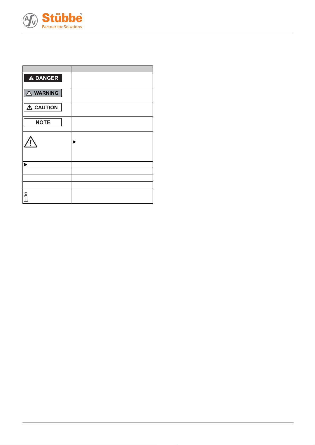
1.3 Warnings and symb ols
About this document
Symbol
1. , 2. , … Multiple-step instructions
→
Tab. 2 Warnings and symbols
Meaning
• Immediate a cute risk
• Death, serious bodily harm
• Potentially acute risk
• Death, serious bodily harm
• Potentially hazardous situation
• Minor injury
• Potentially hazardous situation
• Material damage
Safety warning sign
Take note of all information
highlighted by the safety warning
sign and follow the instructions to
avoid injury or death.
Instruction
Precondition
Cross-reference
Information, advice
300 106 BA-2015.09.17 ETL 5
Page 6

Safety
2 Safety
The manufacturer does not accept any liability for any damage caused by disregarding any sections of the entire documentation.
2.1 Intended use
• Only use the pump with suitable media (→ resistance lists).
• Do not use pump with solid particles or abrasive fluids.
• Do not use pump with combustible or explosive fluids.
• Adhere to the operating limits and size-dependent minimum flow rates.
• Avoid dry running:
Initial damage, such as destruction of bearings, seals and
plastic parts, will occur within a few seconds.
– Make sure the pump is only operated with, and never
without, pumped liquid.
• Avoid cavitation:
– Open suction-side fitting fully and do not use to regulate
flow.
– D o not open the pressure-side fitting beyond the
agreed operating point.
• Avoid overheating:
– Do not operate the pump while the pressure-side fitting
is closed.
–Noteminimumflow (→ Data sheet).
• Avoid damage to the motor:
– D o not open the pressure-side fitting beyond the
agreed operating point.
– Note the maximum permissible number of times the
motor can be switched on per hour (→ manufacturer's
specifications).
• Consult the man ufacturer about any other use of the pu mp.
• If pumps are delivered without m otors, then final assembly
as a pump assembly must take place in accordance with
the provisions of machinery directive 2006/42/EC.
Prevention of obvious misuse (examples)
• Observe pump limits of use regarding temperat
sure, flow and speed (→ Data sheet).
• The power consumption of the pump increases as the the
specific gravity of the pumped fluid increases. Adhere to
the permissible specific gravity in order to eliminate the
possibility that the pump, coupling and mo tor are overloaded (→ Data sheet).
A lower specific gravity is perm issible. Adapt the auxiliary
systems accordingly.
• When conveying fluids containing solids, observe the limit
values for proportions of solid particles and particle size
(→ Data sheet, technical description).
•Whenusinga
– Ensure com
product m
– Ensure
mediu
uxiliary plant systems:
patibility of the operating medium with the
edium.
constant supply of the relevant operating
m.
ure, pres-
• Pumps used with water as the pumped liquid must not be
used for foo dstuffs or drinking water. Use with food or
drinking water must be specified in the data sheet.
• Type o f installation should only be selected in accordance
with these operating instructions. For example, the following are not allowed:
– Hanging base plate pumps in the pipe
– Overhead installation
– Installation in the immediate vicinity of extreme heat or
cold sources
– Installation too close to the wall
2.2 General safety instructions
Observe of the followin g regulations before carrying out
any work.
2.2.1 Product safety
The pump has been built according to state-of-the-art technology and the recognized technical safety regulations. Nevertheless, operation of the pump can still put the life and health
of the user or third parties at risk or damage the pump or other
property.
• Only operate the pump if it is in perfect technical condition
and on ly use it as intended, staying aware of safety and
risks, and in adherence to the instructions in this manual.
• Keep this manual and all oth er applicable documents complete, legible and accessible to personnel at all t imes.
• Refrain from any procedures and actions that would pose
a risk t o p ersonnel or third parties.
• In the event of any safety-relevant faults, shut down the
pump immediately and have the fault corrected by appropriate personnel.
• In add ition to the entire documentation for the product,
comply with statutory or other safety and accident-prevention regulations and the applicable standards and guidelines in the country where the pump is operated.
6 ETL BA-2015.09.17 300 106
Page 7

Safety
2.2.2 Operator's obligations Safety-conscious operation
• Only operate the pump if it is in perfect technical condition
and o nly use it as intended, staying aware of safety and
risks, and in adherence to the instructions in this manual.
• Ensure that the following safety aspects are observed and
monitored:
– Adherence to intended use
– Statutory or other safety and accident-prevention reg-
ulations
– Safety regulations governing the handling of haz-
ardous substances
– Applicable standards and guidelines in the country
where the pump is operated
– Applicable guidelines of the operator
• Make personal protective equipment available.
Qualified personnel
• Make sure all personnel tasked with work on the pump
have read and understood this man ual and all other applicable documents, especially the safety, maintenance and
repair informatio n, before they start any work.
• Organize r esponsibilities, areas of competence and the
supervision of personnel.
• Ensure that all work is carried out by specialist t echnicians
only:
– Fitting, repair and maintenance work
– Transportation
– Work on the electrical system
• Make sure that trainee personnel only work on the pump
under s upervision of specialist technicians.
Safety equipment
• Provide the following safety equipment and verify its fu nctionality:
– For hot, cold and moving parts: pump safety guarding
provided by the customer
– For pumps without capability to run dry: Dry run pro-
tection
– For potential electrostatic chargi ng: provide suitable
grounding
2.2.3 Obligations of personnel
• All directions given on the pump must be followed (and kept
legible), e.g. the arrow indicating the sense of rotation and
the markings for fluid connections.
• Pump, coupling guard and components:
– Do not step on them or use as a climbing aid
– Do not use them to support boards, ramps or beams
– Donotusethemasafixing point for winches or sup-
ports
– Do not use them for storing paper or similar materials
– Do not use hot pump or motor components as a heating
point
– Do not de-ice using gas burners or similar tools
• Do not remove the safety guarding for hot, cold or moving
parts during operation.
• Use p ersonal protective equipment if necessary.
• Only carry out work on the pump while it is not running.
• Before all installation and maintenance work, disconnect the mo tor from the mains and secure against being
switched back on again.
• Never reach into the suction or discharge flange.
• Following all work on the pump, refit safety devices in
accordance with the instructions and bring into service.
2.3 Specifichazards
2.3.1 Hazardous pumped liquids
• When handling hazardous fluids, observe the safety regulations for the handling of hazardous substances.
• Use personal protective equipment when carrying out any
work on the pump.
• Collect leaking pumped liquid and residues in a safe manner and dispose of i n accordance with en vironmental regulations.
Warranty
• Obtain the manufacturer's approval prior to carrying out
any modifications, repairs or alterations during the warranty
period.
• Only use genuine parts or parts that have been approved
by the manufacturer.
300 106 BA-2015.09.17 ETL 7
Page 8
Layout and function
3 Layout and function
3.1 Labels
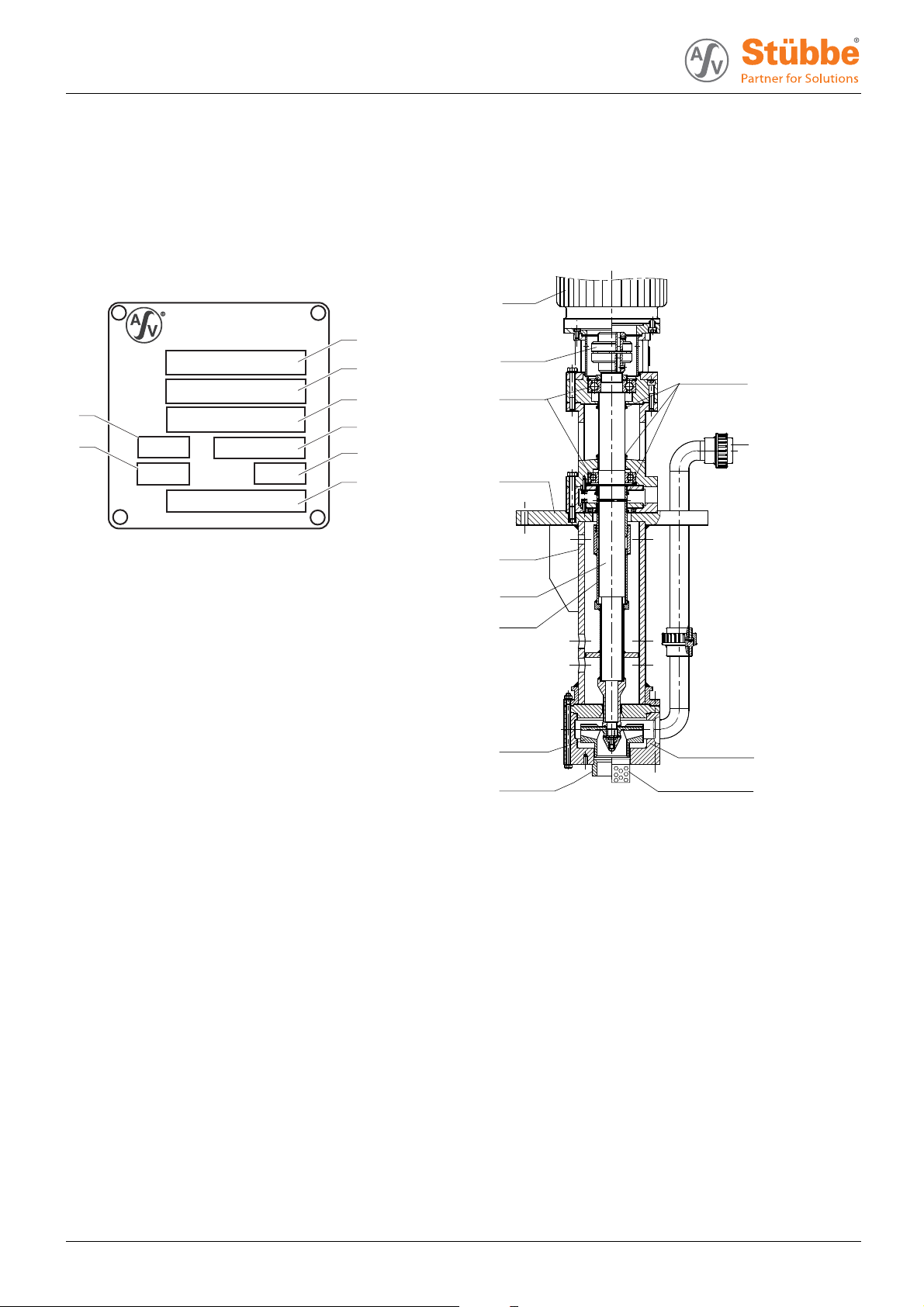
3.1.1 Type plate
ASV Stübbe GmbH & Co. KG
Tel.: +49 (0) 57 33 / 79 9-0
Typ
Fabr. Nr.
8
Werkst.
L ø
7
Q
m
3
/h
H
m
1
2
3
4
5
6
GLRD
Fig. 1 Type plate (example)
1Pumptype
2 Serial number
3 Housing / sealing material
4–
5 Differential head
6 Shaft seal information
7Flow
8 Impeller diameter [mm]
3.2 Description
Non self-priming, vertical centrifugal pump
Useinopenorclosedpressureless containers or pits/trenches.
Thepumpisdry-runningsafe.
3.3 Layout
13
12
11
10
9
8
7
6
5
Fig. 2 Layout
1 V-ring seal
2 Discharge flange
3 Volute casing
4 Strainer (optional)
5Suctioncup
6Impeller
7Protectiontube
8Shaft
9 Immersion tube
10 Sole plate
11 Shaft bearing
12 Coupling
13 Motor
1
2
3
4
8 ETL BA-2015.09.17 300 106
Page 9
4 Transport, storage and disposal
Transport, storage and disposal
4.1 Transport
Weight specifications (→ documents for the particular
order).
4.1.1 Unpacking and inspection upon delivery
1. Unpack the pump/pump assembly upon delivery and
inspect it for transport damage.
2. Check completeness and accuracy of delivery.
3. Report any transport damage to the ma nufacturer immediately.
4. Dispose of packaging material according to local regulations.
Retain transport frame for horizontal storage (recommended)
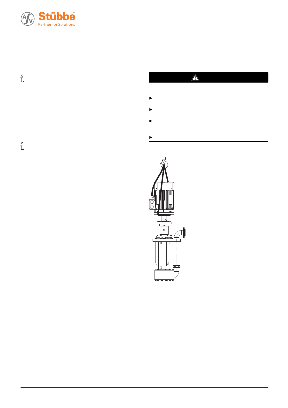
4.1.2 Lifting
DANGER
Death or limbs crushed as a result transported items
falling over.
Use lifting gear appropriate for the total weight to be transported.
Attach lifting gear in accordance with the following diagrams.
Never attach the liftin g gear t o the lifting eye of the motor
(other than for securing against knocking over for pump
assemblies with a high center of gravity).
Do not s tand un der suspended loads.
1. Attach lifting gear in accordance with the following diagram.
2. Lift pump/pump assembly appropriately.
300 106 BA-2015.09.17 ETL 9
Page 10
Transport, storage and disposal
4.2 Storage
DANGER
Death or limbs crushed as a result of the pump overturning.
For vertical storage:
– Place pump on a horizontal undergroun d and secure
against overturning.
NOTE
Material damage due to inappropriate storage!
Store the pump properly.
1. Seal all open ings with blind flanges, blind plugs or plastic
covers.
2. Make sure the storage room meets the following conditions:
–Dry
– F rost-free
– Vibration-free
–UVprotected
3. For horizontal storage
– Protect pump against sagging by means of proper sup-
port.
4. Turn the pump twice a month.
5. Make sure the shaft and bearing change their rotational
position in the process.
4.3 Disposal
Plastic parts can be contaminated by poisonou s or radioactive pumped liquids to such an extent that clean ing will be
insufficient.
WARNING
Risk of poisoning and environmental damage by the
pumped liquid or oil!
Use personal protective equipment when carrying out any
work on the pump.
Prior to the disposal of the pump:
– Collect and dispose of any e scaping pumped liquid or
oil in accordance with local regulations.
– Neutralize residues of pumped liquid in the pump.
Remove the plastic parts and dispose of them in accor-
dance with local regulations.
Dispose of the p um
p in accordance with local regulations.
10 ETL BA-2015.09.17 300 106
Page 11

5 Setup and connection
Setup and connection
NOTE
Material damage due to distortion or passage of electrical
current in the bearing!
Do not make any structural modifications to the pump
assembly or pump casing.
Do not carry out any welding work on the pump assembly
or pump casing.
NOTE
Material damage caused by dirt!
Do not remove the transport seals until immediately before
setting up the pump.
Do not remove any covers or transport and sealing covers
until immediately before connecting the pipes to the pump.
5.1 Preparing the setup
5.1.1 Check operating conditions
1. Ensure the required operating conditions are met:
– Resistance of body and seal material to the medium
(→ resistance lists).
– Required ambient conditions
(→ 9.2.1 Ambien t conditions, Page 26).
2. Ensure necessary dimensions for tank cut-out (→ Data
sheet).
3. Ensure safe aeration and venting of the contai ner in all
operating phases.
4. Ensure required installation dimensions and filling levels (→ 9.2.6 Installation dimensions and fillin g heights,
Page 27).
– Minimum distances
–Maximumfilling height
–Minimumfilling height
5.1.3 Surface preparation
Aids, tools, materials:
– Spirit level
1. Make sure the surface meets the following conditions:
– Level and horizontal
– Clean (no oil, dust or other impurities)
– Capable of bearing the weig ht of the pump assembly
and all operating forces
– Stability of the pump ensured
– Resonance-free
2. Clean containers, basins or pits carefully and protect from
further contamination, e.g. by installing overflow wall in
front of the container or pit inlet.
5.2 Setting up
1. Remove the suction-side cover if present.
2. Lift pump/pump assembly (→ 4.1 Transport, Page 9 ).
3. Place pump/pump assembly on the contact surface of the
container/pit.
4. Attach sole plate to the contact surface.
– Pump must not be mechanically under tension as a
result of being attached
5. Screw on the sole plate (→ 9.2.4 Sole plate tightening
torques, Page 26).
5.1.2 Preparing the installation site
Ensure the installation site meets the following conditions:
– Pump is freely accessible from all sides
–Sufficient space for the installation/removal of the pip es
and for maintenance and repair work, especially for the
removal and installation of the pump and the motor
– Pump not exposed to external vibrations (damage to
bearings)
– Frost protection
300 106 BA-2015.09.17 ETL 11
Page 12

Setup and connection
5.3 Planning the pipes
Water hammers may damage the pump or the system.
Plan the pipes and fittings as far as possible to prevent
water hammers occurring.
5.3.1 Specifying supports and flange connections
NOTE
Material damage due to excessive forces and torq ues on
the pump.
Ensure pipes are connecte d not under tension.
1. Support pipes in front of the pump.
2. Ensure the pipe s upports have permanent low-friction
properties and do not seize up due to corrosion.
5.3.2 Specifying nominal widths
Keep the flow resistance in the pipes as low as possible.
1. Make sure the suction extension is not smaller than the
nominal width of the suctio n branch.
2. Make sure the nominal pressure line width is not smaller
than the nominal discharge flange width.
– Ensure fl ow velocity is less than 3 m/s.
5.4 Connecting the pipes
NOTE
Material damage due to excessive forces and torq ues on
the pump.
Ensure pipe connection without tension.
5.4.1 Keeping the piping clean
NOTE
Material damage due to impurities in the pump!
Make sure no impurities can enter the pump.
1. Clean all piping parts and fittings prior to assembly.
2. Flush all pipes carefully with neutral medium.
3. Ensure no flange seals protrude inwards.
4. Remove any blind flanges, plugs, protective foils and/or
protective paint from the flanges.
5.4.2 Installing the pressure pipe
1. Remove the transport an d sealing covers from the pump.
2. Fit pressure line stress-free an d sealed. (→ 9.2.3 Flange
tightening torques, Page 26).
3. Ensure no seals protrud e inward s .
5.3.3 Optimizing changes of cross section and direction
1. Avoid radii of curvature of less than 1.5 times the nominal
pipe diameter.
2. Avoid abrupt changes of cross-section along the piping.
5.3.4 Providing safety and control devices (recommended)
Avoid reverse running
1. Ensure that the medium does not flow back after switch-
ing off the pump by using a non-return valve between discharge flange and stop valve.
2. In order to enable venting, inclu de vent connection
between discharg e flanges and non-return valve.
Make provisions for isolating and shutting off the pipes
For maintenance and repair work.
Provide shut-off devices in the pressure pipe.
Allow m easurements of the operating conditions
1. Provide pressure gauge in pressure line for pressure mea-
surement.
2. Provide pressure measurement on the pump side.
5.4.3 Inspection for stress-free pipe connections
Piping installed and cooled down
1. Disconnect the pipe connecting flanges from the pump.
2. Chec k whether the pipes can be moved freely in all directions within the expected range of expansion:
– Nominal width < 150 mm: by hand
– Nominal width > 150 mm: with a small lever
3. Make sure the flange surfaces are parallel.
4. Reconnect the pipe connecting flanges to the pump.
12 ETL BA-2015.09.17 300 106
Page 13

5.5 Electrical connection
DANGER
Risk of death due to electric shock!
All electrical work must be carried out by qualified electricians only.
Before all work on the electrical system, disconnect the
motor from the mains and secure against being switched
back on again.
5.5.1 Connecting the motor
Follow the instructions of the motor manufacturer.
1. Connect the motor according to the connection diagram.
2. Make sure no danger arises due to electric p ower.
3. Install an EMERGENCY STOP switch.
5.5.2 Check direction of rotation
Setup and connection
DANGER
Danger to life from rotating parts
Use personal protective equipment when carrying out any
work on the pump.
Maintain an adequate distance from rotating parts.
1. Switch on motor for max. of 2 seconds and switch off again
immediately.
2. Check whether the sense of rotation of the motor matches
the d irection of rotation on the fan.
3. If the sense of rotation is different: Change over the two
phases.
5.6 Performing the hydrostatic test
Only necessary if the entire system needs to be tested
under pressure.
NOTE
Material damage due to bursting of pump casing.
Testing pressure must not exceed the permissible pum p
pressure (→ order data sheet).
Make sure the testing pressure does not exceed the permissible pump pressure.
– If necessary, do not perform pressure test on the pump.
300 106 BA-2015.09.17 ETL 13
Page 14

Operation
6Operation
6.1 Preparing for commissioning
6.1.1 Checking downtimes
Check downtimes (→ Table 5 Measures to be taken after
prolonged shutdown periods, Page 16).
6.1.2 Filling and bleeding
WARNING
Risk of injury and poisoning due to hazardous fluid!
Use protective equipment for any work on the pump.
Collect leaking liquid safely an d dispose of in accordance
with local regulations.
1. Close pressure-side fitting.
2. Fill pump and, if present, suction pipe with fluid.
Ensure minimum filling height when doing so (→ Ta b le
13 Installation dimensions (minimum dimensions),
Page 27).
3. Verify that no pipe connections are leaking.
6.2 Commissioning
6.2.1 Switching on
Pump set up and connected properl y
Motor set up and connected properly
All connections stress-free and se aled
All safety equipment installed and tested for functionality
Pump prepare d, filled and vented correctly
Container is filled sufficiently up to minimum height
“Z” (→ 9.2.6 Installation dimensions and filling heights,
Page 27).
NOTE
Risk of cavitation if suction flow is restricted.
Open the suction-side fitting and do not use to regulate the
flow.
Do not open the pressure-side fitting beyond the operating
point.
NOTE
Material damage due to overheating.
Do not operate the pump for long periods w ith the pressureside fitting closed.
Observe minimum flow ( order data sheet).
1. Open the suction-side fitting.
2. Close pressure-side fitting
3. Switch on the motor and check it for smooth running.
4. Once the motor has reached its nominal speed, open
the pressure-side fitting slowly until the operating point is
reached.
5. Make sure temperatu r e change i s smaller than 5 K/min for
pumps with hot fluids.
6. After the initial stress due to the pressure and operating
temperature, check that the pump is not leaking.
6.2.2 Switching off
Pressure-side fitting closed (recommended)
WARNING
Risk of inju ry du e to hot pump parts!
Use personal protective equipment when carrying out any
work on the pump.
DANGER
Risk of injury from running pump.
Do not touch the running pump.
Ensure that the coupling gua rd is attached.
Do not carry out any work on the running pump.
Allow the pump to cool down completely before starting any
work.
1. Switch off motor.
2. Check all connecting bolts and tighten if necessary (only
after initial commissioning).
DANGER
Risk of injury a
ing out!
Use personal protective equipment when carrying out any
work on the pump.
14 ETL BA-2015.09.17 300 106
nd poisoning due to pumped liquid spray-
Page 15

Operation
6.3 Shutting down the pump
DANGER
Risk of injury from running pump
Do not touch the running pump.
Do not carry out any work on the running pump.
Before all installation and maintenance work, discon-
nect the mo tor from the mains and secure against being
switched back on again.
DANGER
Risk of electrocution!
All electrical work must be carried out by qualified electricians only.
Before all work on the electrical system, disconnect the
motor from the mains and secure against being switched
back on again.
WARNING
Risk of injury and poisoning due to hazardous fluid!
Use protective equipment for any work on the pump.
Collect leaking liquid safely and dispose of fitting in accor-
dance with local regulations.
Take the following measures whenever the pump is shut
down:
Pump is Action
shut down
…emptied
…dismounted
…put into
storage
Tab. 3 Measures to be taken if the pump is shut down
Behavior of the
pumped liquid
Crystallized or
polymerized,
solids
sedimenting
Solidifying/
freezing,
non-corrosive
Solidifying/
freezing,
corrosive
Remains liquid,
non-corrosive
Remains liquid,
corrosive
Tab. 4 Measures depending on the behavior
of the pumped liquid
Take measures appropriate for
the fluid (→ Table 4 Measures
depending on the behavior of
the pumped liquid, Page 15).
Close suction and pressure-side
fitting.
Isolate the motor from its power
supply and secure it against
unauthorized switch-on.
Note measures for storage.
Duration of shutdown (depending
on process)
Short
Flush the
pump.
Heat up or
empty the
pump and
containers.
Heat up or
empty the
pump and
containers.
––
–
Long
Flush the
pump.
Empty the
pump and
containers.
Empty the
pump and
containers.
Empty the
pump and
containers.
300 106 BA-2015.09.17 ETL 15
Page 16

Operation
6.4 Restoring the pump to service
1. If the pump is shut down for over 1 year, take the following
measures before restoring it to service:
Shutdown period
>2years Replace elastomer seals
Tab. 5 Measures to be taken after prolonged
shutdown periods
2. Complete all steps as for commissioning
(→ 6.2 Commissioning, Page 14).
Action
(O-rings, shaft sealing rings).
6.5 Operating the stand-by pump
Stand-by pump filled and bled
Operate the stand-by pump at least once a week.
Open pressure-side fitting far enough so that the stand-by
pump operating temp erature is achieved and heating is
even ( → 6.2.1 Switching on, Page 14).
16 ETL BA-2015.09.17 300 106
Page 17

7 Maintenance
Maintenance
Trained service technicians are available for fitting and
repair work. Submit evidence of conveyed medium on
request (DIN safety data sheet or safety certificate).
7.1 Inspections
The inspection intervals depend on the operational strain
on the pump.
DANGER
Risk of injury due to running pump!
Do not touch the running pump.
Do not carry out any work on the running pump.
WARNING
Risk of injury and poisoning due to hazardous pumped
liquids!
Use protective equipment for any work on the pump.
1. Check at appropriate intervals:
– Adherence to the min imum flow rate
– Normal operating conditions unchanged
– Filling level of the container
2. Fo r trouble-free operation, always ensure the fo llowing:
–Noleaks
– No cavitation
– Free and clean filters
– No unusual running n oises or vibrations
– No inadmissible leaks on the shaft seal
7.2 Maintenance
Operating life of an tifrictio n bearings in operation are within
permissible range: >2 years.
Intermittent operation, high temperatures, low viscosities
and aggressive ambient and process conditions reduce the
service life of antifriction bearings.
Plain bearings are subject to natural wear and tear which
is heavily dependent on the respective operating conditions. It is therefore not possible to make general statements about the operating life.
DANGER
Risk of injury from running pump
Do not touch the running pump.
Do not carry out any work on the running pump.
Before all installation and maintenance work, discon-
nect the mo tor from the mains and secure against being
switched back on again.
DANGER
Risk of electrocution!
All electrical work must be carried out by qualified electricians only.
Before all work on the electrical system, disconnect the
motor from the mains and secure against being switched
back on again.
DANGER
Danger to life from rotating parts
Ensure coupling guard is fitted after work on the pump.
WARNING
Risk of injury and poisoning due to hazardous or hot fluid.
Use protective equipment for any work on the pump.
Allow the pump to co ol down completely before commenc-
ing any work.
Make sure the pump is unpressurized.
Empty the pump, s afely collect the pumped liquid and
dispose of it in accordance with environmental rules and
requirements.
7.2.1 Maintenance in accordance with maintenance schedule
Perform maintenance work in accordance with the maintenance schedule (→ 9.3 Maintenance plan, Page 27).
300 106 BA-2015.09.17 ETL 17
Page 18

Maintenance
7.2.2 Cleaning the pump
NOTE
High water pressure or spray water can damage bearings!
Do not clean bearing areas with a water or steam jet.
Clean l arge-scale grime from the pump.
7.3 Dismounting
DANGER
Risk of injury due to running pump!
Do not touch the running pump.
Do not carry out any work on the running pump.
Before all installation and maintenance work, discon-
nect the motor from the mains and secure against being
switched back on again.
DANGER
Risk of electrocution!
All electrical work mus t be carried out by qual i fied electricians only.
Before all work on the electrical system, disconnect the
motor from the mains and secure against being switched
back on again.
DANGER
Death or limbs crushed as a result of the pump overturning.
Place pump on a horizontal underground and secure
against overturning.
WARNING
Risk of injury and poisoning due to hazardous or hot fluid.
Use protective equipment for any work on the pump.
Allow the pump to cool down completely bef
ing any work.
Make sure the pump is unpressurized.
Empty the pump, s afely collect the pumped liquid and
dispose of it in accordance with environmental rules and
requirements.
ore commenc-
WARNING
Risk of injury during disassembly!
Secure the pressure-side gate valve against accidental
opening.
Depressurize the blocking pressure system, if available.
Wear protective gloves, components can be very sharp-
edged due to wear or damage.
Remove spring-lo ad ed components carefully (e.g.
mechanical seal, tensioned bearing, valves etc.), as components can be ejected by the spring tension.
Observe the manufacturer's specifications (e.g. for the
motor, coupling, mechanical seal, blocking pressure system, cardan sh aft, drive s , belt drive etc.).
NOTE
Material damage due to incorrect dismounting/installation
of the pump.
Only specialist mechanics should complete dismounting/
installation work.
7.3.1 Preparations for dismounting
Pump is depressurised
Pump completely empty, flushed and decontaminated
Electrical connections disconnected and motor secured
against switch-on
Pump cooled down
Manometer lines, manometer and fixtures dismounted
When dismounting, observe the following:
– Mark the precise orientation and position of all compo-
nents before dismounting them.
– Dismount components concentrically without canting.
– Dismount pump (→ sectional drawing).
7.3.2 Dismounting hydrau lic system
1. Undo the pressure pipe screw connection between spiral
casing and sole plate.
2. Screw out the hexagon screws or stud bolts (901.2 or
902.1) from the spiral casing (102).
3. Pull the spiral casing (102) to the bottom.
– Donottiltthespiralcasing
– Do not damage the centering and impeller
4. Remove the impeller cap (260) including O-ring (412.4).
5. Screw out the hexagon nut (920.1), r
(934.0) and disc (550).
6. Screw out the impeller (230) from the shaft (211).
7. Remove the key (940.2) and O-ring (412.3).
emove spring ring
WARNING
Risk of injur y due to heavy components!
Pay atte
heavy c
Set down components safely and secure them against
overturning or rolling away.
18 ETL BA-2015.09.17 300 106
ntion to the component weight. Lift and transport
omponents using suitable lifting gear.
7.3.3 Dismounting coupling
1. Screw out screws on the motor flange, re move motor (801)
and motor-side coupling half (840.1).
2. Screw out screws (
(341).
3. Remove intermediate ring.
4. Undo stud bolt (840.2) and remove pump - side coupling
half.
901.3) and remove motor bell housing
and intermediate ring
Page 19

Maintenance
7.3.4 Dismounting V-rings
1. Screw out nuts (920.4) and screws (554.3) and remove
motor (801).
2. Dismounting hydraulic system (→ 7.3.2 Dismounting
hydraulic system, Page 18).
3. Remove the housing cover (161).
4. Remove shaft protection tube (714).
5. Screw out fastenin g screws (901.7).
6. Remove the suspension pipe (713) including reinforcement
plate (893.2) from the drive assembly group.
7. Remove intermediate ring (509) and V-ring.
8. Remove sealing washer (444).
9. Pull off the sealing flange (490) from the bearing bracket
mounting (330).
10. Remove V-ring in the bearing cover (360.2).
7.3.5 Dismounting shaft bearing
1. Remove V-rings step 1 to 9 (→ 7.3.4 Dismounting V-rings,
Page 19).
2. Press out the spring dowel sleeves (531) in the shaft sleeve
area (523.1).
3. Remove the shaft sleeve (523.1) from the shaft.
4. Screw out socket head cap screws (914.4).
5. Remove bearing cover (360.2).
6. Bend the stem of the securing plate (931.1) to one side and
undo the shaft nut (921.1).
7. Press the shaft assembly group (211) including distance
sleeve (525) and the shaft bearing (321.1) out of the bearing s upport towards the hydra ul ics side.
8. Screw out headless setscrews (904.1).
9. Remove the sleeve (525) from the shaft.
10. Press out shaft bearing (321.1) and labyrinth disc (555).
11. Remove the circlip (932.2) from the bearing sup port.
12. Press the bearing (321.1) including the top labyrinth disk
(555) out of the bearing support (330).
7.4 Replacement parts and return
1. Have the following information ready to hand when ordering spare parts
–Devicetype
– ID number
– Nominal pressure and diameter
– Connection and gasket material
2. Please complete and enclose the document of compliance
for returns
(→ www.asv-stuebbe.de/pdf_DOC/300359.pdf).
300 106 BA-2015.09.17 ETL 19
Page 20

Maintenance
7.5 Installing
Install components concentrically and without tilting in
accordance with the markings applied.
WARNING
Risk of injury due to heavy components
Pay attention to the component we ight. Lift and transport
heavy components using suitable lifting gear.
Set down components safely and secure them against
overturning or rolling away.
WARNING
Risk of injury during assembly!
Install spring-loaded components carefully (e.g. mechanical seal, tensioned bearing, valves etc.), as components
can be ejected b y the spring tension.
Observe the manufacturer's specifications (e.g. for the
motor, coupling, mechanical seal, blocking pressure system, cardan sh aft, drive s , belt drive etc.).
NOTE
Material damage due to incorrect dismounting/installation
of the pump.
Only specialist mechanics should complete dismounting/
installation work.
NOTE
Material damage due to unsuitable components!
Always replace lost or damaged screws with screws of the
same strength where required.
Only replace seals with seals of the same material.
NOTE
Material damage, fragile components
Install ceramic parts of the plain bearing and magnets of
the magnetic coupling with care, do not hit or knock.
1. When installing please observe:
– Replace wo rn parts with genuine spare parts.
– Replace seals, inserting them in such a w ay that they
are unable to rotate.
– Do not apply synthetic or mineral oil, grease or cleaning
agents to elastomer components.
– Adhere to the prescribed tightening torques
(→ 9.2.5 Tightening torques of ca sing screws,
Page 26).
2. Installing
–in reverse
– → sectio
3. Installing the pump in the system (→ 5 Setup and connection, Page 11).
the pump:
(→ 7.3 Dis
order to the dismounting
mounting, Page 18).
nal drawing
20 ETL BA-2015.09.17 300 106
Page 21

8 Troubleshooting
If faults occur which are not specified in the following table or
cannot be traced back to t he specified causes, please consult
the manufacturer.
Possible faults are identified by a fa ult number in the tabl e
below. This number identifies the respective cause and remedy in the troubleshooting list.
Fault Number
Pump not pumping 1
Pumpingrateinsufficient
Pumping rate excessive 3
Pumping pressure insufficient
Pumping pressure excessive
Pump running roughly 6
Pump leaks
Excessive motor power uptake 8
Tab. 6 Fault/number assignment
2
4
5
7
Troubleshooting
Fault number
1234
–––––––
X
XX–X
–––––––
X
—
–
X
XX–X
XX–X
–
–
XX–X
–
XX
—
X
–
X
––––X––
–
X
–
X
––
X
––
5
6
–
X
—
X
X
X
X
X
–
X
–
X
–
X
–
X
–––
––––
XX
XX
7
8
––
——
––
––
––
––
X
––
––
Cause
Pressure pip e closed by fitting
Pump or suction s trainer blocked or
encrusted
Transport and sealing cover still in place Remove the transport and sealing cover.
Counterpressure of system is too high,
pump selected is too small.
Suction head too large: NPSH
than NPSH
intake/suction pipe and pump not correctly
vented or not completely filled
Air is sucked in
Proportion of gas too high: pump is
cavitating
Temperature of fluid is too high: pump is
cavitating
Viscosity or specific gravity of the pumped
liquid outside the range specified for the
pump
Geodetic differential head and/or pipe flow
resistances too high
Pressure-side fitting not opened wide
enough
Pressure pipe blocked
system
pump
is larger
Remedy
Open the fitting.
Clean intake/suction pipe, pump or
suction strainer.
Consult with the manufacturer.
Increase pump inlet pressure.
Consult with the manufacturer.
Completely fill and vent pump and/or
pipe.
Check filling level of container.
Consult with the manufacturer.
Increase pump inlet pressure.
Lower temperature.
Contact the manufacturer.
Consult the manufacturer.
Remove sediments from the pump
and/or pressure pipe.
Install a larger impeller and consult the
manufacturer.
Open the pressure-side fitting.
Clean the pressure pipe.
300 106 BA-2015.09.17 ETL 21
Page 22

Troubleshooting
Fault number
1234
XX–X
XX–X
–
––
–
X
XX–X
X
5
–
––––
–
6
X
X
7
––
––
–
––X––X–
––X–
––X–
––X–
XX–X
–
–
X
X
–––
X
XX–X Motor speed too high
XX–X Impeller diameter too large
–
–
X
X
––
––
–– –– –X–
–– –– –X–
–– –– ––X–
–– –– ––X–
–– –– –
–
–
X
X
X X X Pump distorted
–
–
X
Tab. 7 Troubleshooting list
Cause
8
Pump running in the wrong direction
Motor speed too low
Pump parts worn
X
Pressure-side fitting opened too wide
X
Geodetic differential head, pipe flow
resistances and/or other resistances lower
than specified
Viscosity lower than expected
Impeller out of balance or blocked
Hydraulic parts of the pump dirty, clotted or
encrusted
X
Shaft bearing faulty
X
Defective antifriction bearing in motor
Connecting bolts not correctly tightened
Faulty housing seal
X Motor running on 2 phases
Remedy
Check sense of rotation and correct if
necessary (→ 5.5.2 Check direction of
rotation, Page 13).
Compare the required motor speed with
the specifications on the pump type
plate. Replace the motor if necessary.
Increase the motor speed if speed
control is available.
Replace the worn pump parts.
Throttle down at the pressure-side fitting.
Machine t he impeller down. Consult the
manufacturer and a djust the impeller
diameter.
Throttle down the flow rate at the
pressure-side fitting. Observe the
minimum flow rate.
Machine t he impeller down. Consult the
manufacturer and a djust the impeller
diameter.
Machine t he impeller down. Consult the
manufacturer and a djust the impeller
diameter.
Compare the required motor speed with
the specifications on the pump type
plate. Replace the motor if necessary.
Reduce the motor speed if speed control
is available.
Throttle down the flow rate at the
pressure-side fitting. Observe the
minimum flow rate.
Machine t he impeller down. Consult the
manufacturer and a djust the impeller
diameter.
Clean the impeller.
Dismount the pump.
Clean the parts.
Replace shaft bearing.
Replace the antifriction bearing
(→ manufacturer 's specifications).
Tighten the connecting bolts.
Replace housing seal
Check the pipe connections and pump
attachment.
Check the fuse and replace it if
necessary.
Check the cable connections and
insulation.
22 ETL BA-2015.09.17 300 106
Page 23

9 Appendix
Appendix
9.1 Replacement parts
9.1.1 Part numbers and designations
Part no. Designation
102 Volute casing
161 Housing cover
211
230 Impeller
260 Impell er cap
321.1 Bearing
321.2 Bearing
330 Bearing bracket
341 Motor bell housing
360.2 Bearing cap
412.x
444
490
507.1 V-ring
509 Intermediate ring
523.1
525 Distance sleeve
531
550 Disc
554.x Disc
555
556 Round head grooved pin
636
681.1
681.2
710
713
714
716 P ressure connection
801 Motor
840.1/2 Coupling
860 Intermediate ring
893.2
901.x Hexagon head bolt
Shaft
O-ring
Sealing washer
Sealing flange
Shaft sleeve
Clamping sleeve
Centrifugal disk
Grease nipple
Coupling g
Contact guard
Suction e xtension
Sole plate with support tube
Shaft protection tube
Reinforcement plate
uard
Part no. Designation
902.1
904.1 Headless setscrew
914.4
920.x Hexagon nut
921.1
931.x Locking plate
932.2
934
940.x Key
970.3 Name plate
Tab. 8 Designation of components according
to part numbers
Stud bolt
Cylinder screw
Shaft nut
Circlip
Spring ring
300 106 BA-2015.09.17 ETL 23
Page 24

Appendix
9.1.2 Drawing ETL 20-100 to 65-200
A
B
Fig. 3 Replacement parts ETL 20-100 to 65-200
ASize132
B Suction basket (optional)
24 ETL BA-2015.09.17 300 106
Page 25

9.1.3 Drawing ETL 80-200
Appendix
Fig. 4 Replacement parts ETL 80-200
300 106 BA-2015.09.17 ETL 25
Page 26

Appendix
9.2 Technical specifications
Further technical data (→ Data sheet).
9.2.1 Ambient conditions
Operation under any other ambient conditi ons should be
agreed with the manufacturer.
Temperature [°C]
–20 to +401)≤ 85 ≤ 100 ≤ 1000
Tab. 9 Ambient conditions
1) material-dependent
9.2.2 Sound pressure level
Sound pressure level < 75 dB(A)
Measuring conditions:
• Distance to the pump: 1 m
• Operation: free of cavitation
• Motor: IEC standard motor
• Tolerance ±3 dB
Relative humidity [%]
Long-term
Short-term
Setup
height
above sea
level [m]
9.2.5 Tightening torques of casing screws
Size
M6 9 6
M8 21
M10421410
M12732425
M16 170 63 30
M20 340 113 32
M24 580 193 34
Tab. 12 Tightening torques of casing screws
Metal connections
Plastic connections
7
Plastic connections
with metal
inserts
5
6
9.2.3 Flange tightening torques
DN [mm] Md [Nm] DN [mm] Md [Nm]
15 15 80 40
20 15 100 45
25 15 125 50
32 25 150 65
40 35 200
50 40 250 100
65 40 300 110
Tab. 10 Flange tightening torques
9.2.4 Sole plate tightening torques
Screw
M8
M10 14 M20 113
M12 24 M24 193
Tab. 11 Sole plate tightening torques
Md [Nm]
7
Screw
M16 63
75
Md [Nm]
26 ETL BA-2015.09.17 300 106
Page 27

Appendix
9.2.6 Installation dimensions and filling heights
Z
Size
20-100 80 110 170 100 10
25-125 80 110 170 100 10
32-125 80 140 170 125 15
32-160 80 140 170 125 15
32-200 80 140 170 125 15
40-125 80 140 170 150 10
40-160 80 160 170 150 10
40-200 80 160 170 150 10
50-125 80 160 170 125 35
50-160 80 160 170 125 35
50-200 80 160 170 125 35
65-200 80 160 170 150 35
80-200 80 180 170 170 35
Tab. 13 Installation dimensions (minimum dimensions)
O
VZXY
[mm]
9.3 Maintenance plan
Fig. 5 Installation dimensi
Max: maximum filling height
Min: minimal filling height
Z: Minimum heigh
t
ons and filling heights
Designation Interval Maintenance
Operating
temperatures
Undoable
screwed
connections
Shaft bearing
(only for
drive capacity
≥ 30 kW)
Impeller
Coupling and
intermediate
ring
Intermediate
ring
14
Tab .
Weekly
Weekly
Monthly
Quarterly
Quarterly Check coupling and
5000 h Replace intermediate ring
tenance plan
Main
Check storage
temperature
Check motor temperature.
Check for correct and tight
fitting.
Re-grease shaft bearing
(→ 9.4 Lubri c ation,
Page 28).
Check impeller for wear
and damage
Clean or replace impeller
intermediate ring for wear.
Replace worn
components
The dimensions and minimum dimension s specified in the
table must not be less than stated.
300 106 BA-2015.09.17 ETL 27
Page 28

Appendix
9.4 Lubrication
Only for version with labyrinth seal.
9.4.1 Lubricating p oints
A
9.4.2 Lubricant
Manufacturer Type of lubricant
temperature range
–35 °C … +140 °C
Aral Aralub HL3
BP
Glissando Glissando FT3
Esso Beacon 3
Mobilux Mobilux EP3
Shell
Tab. 15 Lubricant
Size Quantity [g]
40-200
Tab. 16 Lubricant quantities
Energrease LS3
Glissando 30
Alvania R3
5.5
A
Fig. 6 Lubricating points
A Lubricating points
28 ETL BA-2015.09.17 300 106
Page 29

9.5 Declaration of conformity in
accordance with EC machinery
directive
CE declaration of conformity
We hereby declare under our sole responsibility that the products listed below
Description
Centrifugal pumps with mechanical seal
NM,NMB,SHB
Solenoid pumps
SHM
Eccentric pumps
Type F, Type L
Sump pumps
ET, ETL, ETLB
to which this declaration relates, are in conformity with the following standards:
Machinery Directive 2006/42/EC
EMV Directive 2004/108/EC
With regard to electrical risks, the protection objectives of the Low Voltage Directive
2006/95/EC have been complied with in accordance with appendix I no. 1.5.1 of
the Machinery Directive 2006/42/EC.
Place and date
____________________
Vlotho, 19.08.2013
Name and signature of authorized person
____________________________________
p.p. Achim Kaesberg,
Head of Electrical Engineering
Appendix
300 106 BA-2015.09.17 ETL 29
Page 30

Appendix
30 ETL BA-2015.09.17 300 106
Page 31

Appendix
300 106 BA-2015.09.17 ETL 31
Page 32

Appendix
32 ETL BA-2015.09.17 300 106
 Loading...