

SSV Works RZ3-FKP65, RZR900, RZR XP1000 Installation Manual
SSV WORKS, 201 N. Rice Ave Unit A, Oxnard, CA 93030
www.SSVworks.com | Phone: 818-991-1778 | Fax: 866-293-6751
RZ3-FKP65
RZR XP1000 & 2015+ RZR900
6.5” Speaker Front Kick Panels
WARRANTY INFORMATION:
All SSV Works enclosures are covered by a limited lifetime warranty against defects
in material or workmanship. All SSV Works Electronics are covered by a limited 1 year
warranty against defects in material or workmanship. All SSV Works Speakers are
covered by a limited 1 year warranty against defects in material or workmanship. Labor
for replacement of defective components is not covered. Contact SSV Works for further
warranty information.
TOOLS NEEDED FOR INSTALLATION
- Wire Crimpers
- Wire Strippers
- T-40 Torx Driver
- 7/16” Open End or Socket
- 5/32 Allen Wrench
- Drill with 1/4” and 1/8”
Drill bit
- #2 Phillips Screwdriver
- Utility Knife
- Scribe or Marker
PARTS LIST
1. RZ3-FKP65-U Enclosures (1 pair)
2. 1/4” x 20 Allen Bolt x 6
!
Please read and understand these
instructions completely before
installation to avoid possible injury, or
damage to the accessory or vehicle.
3. 1/4” Washers x 6
4. 7/16” Nut x 6
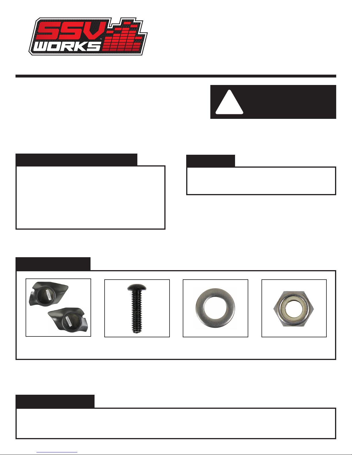
PARTS LIST IMAGES
1. RZ3-FKP65 Enclosures
(1 pair)
2. 1/4 x 20 Allen Bolt x 6
3. 1/4” Washers x 6 4. 7/16” Nut x 6
INSTALLATION NOTES
The use of a thread locker is recommended on all screws to prevent loosening due to vibration. If installing an SSV Works RZ3-GBSB10 Glove
Box subwoofer enclosure, install the subwoofer enclosure rst, then complete the passenger side kick panel installation. The removal of the
fender are is not required; however it will make the installation easier.
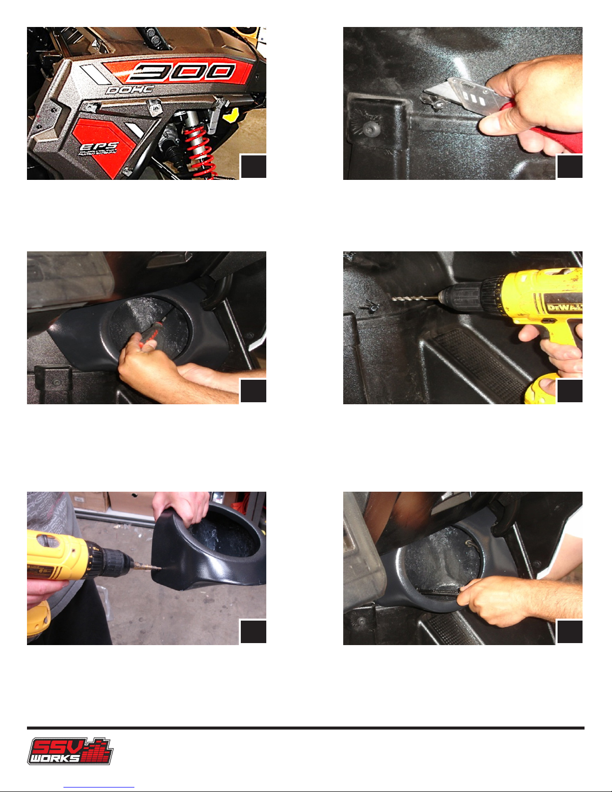
A
B
A. Remove the ten T40 Torx bolts that secure the 2 piece fender.
Note: there is one screw inside the fender well. Remove the
two additional screws from the striker plate, slide fender up
the cage rail and secure
C D
C. Align the kick panel against the rewall and side of the vehicle
(under the glove box on the passenger side & mid way up the
rewall on the driver side), the pod is in the correct location
when it sits ush against the re wall and side walls. Using the
scribe, mark the 3 mounting holes
B. Using the utility knife or another cutting tool cut off the two
plastic factory nubs in the foot well, cut these as smooth as
you can to the panel
D. After marking the holes, drill the 3 mounting locations on
each side using the ¼” drill bit
E. Drill a hole in each kick panel for the speaker wire to exit
(seal this hole with silicone sealer for increased sound and
weatherproong). The hole can be on the top, or the side of the
enclosure, if the side is chosen, the side wall of the vehicle will
need to be drilled for the speaker wire to exit the interior
RZ3-FKP65
FE
F. Once the mounting holes and the speaker wire hole have
been drilled mount the kick panel in the vehicle, installing
the Allen bolt with the the nut on the inside of the enclosure is
recommended
 Loading...