

SSV Works Polaris RZR XP 1000, Polaris RZR XP 900 Installation Manual

PHASE
5
®
®
RZR
POLARIS
pg 2
Disassembly, Wire and
Amplier Plate Installation
POWERSPORTS AUDIO KIT
pg 9
Glovebox Subwoofer
Installation
pg 13
Kick Panel Speakers
Installation
pg 25
Cage Mount Speakers
Installation
pg 29
MRB3 and Dash Kit
Installation

2
RZ3-5K
Polaris RZR XP 1000 & 900
Kicker 5 Speaker Audio Kit
WARRANTY INFORMATION:
All SSV Works enclosures are covered by a limited lifetime warranty against defects in
material or workmanship. All SSV Works Electronics are covered by a limited 1 year warranty
against defects in material or workmanship. All Kicker Speakers are covered by a limited 1
year warranty against defects in material or workmanship. All Kicker Ampliers are covered by
a limited 2 year warranty against defects in material or workmanship. Labor for replacement
of defective components is not covered. Contact SSV Works for further warranty information.
TOOLS NEEDED FOR INSTALLATION
- T30 & T40 Torx Socket
- 10mm and 5.5mm Socket
& Rachet or Wrench
- 4mm & 5mm Allen Wrench
- #2 & #3 Phillips Screwdriver
- Drill with 1/8”, 1/4” & 1/2”
Drill bits
- Panel removal tool
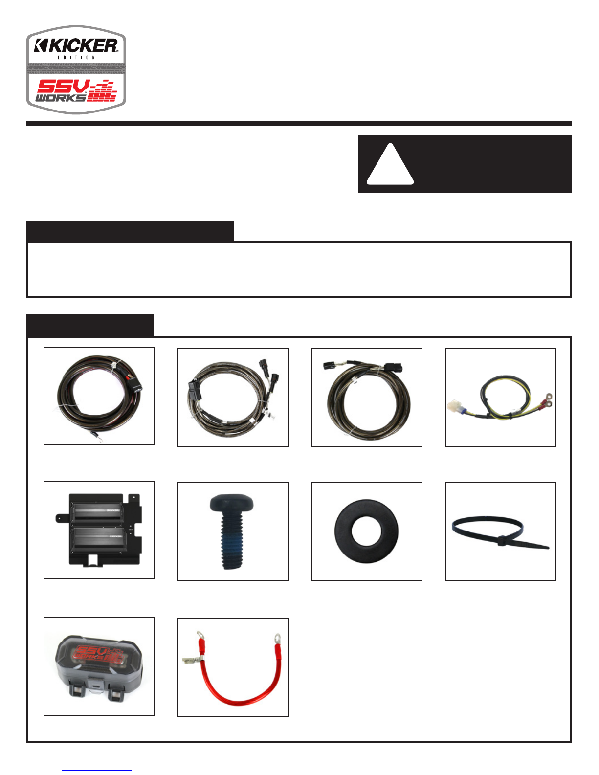
PARTS LIST IMAGES
!
- Wire Crimpers
- Wire Strippers
Please read and understand these
instructions completely before
installation to avoid possible injury, or
damage to the accessory or vehicle.
- Scribe or Marker
- Utility Knife
1. Amp Power Wire
5. Direct-t Amp Plate with pretuned Amp(s) and MRB3 Brain
9. Fuse Holder with 40A Fuse
2. Front B-H1149 Speaker Wire
6. M6 x 1.0 Screws x 1
10. Battery Terminal Cable
3. Rear B-H1151 Speaker
Expansion
7. M6 Washer x 1 8. Zip Ties x 5
4. MRB3 Power & Ground
Connector
3
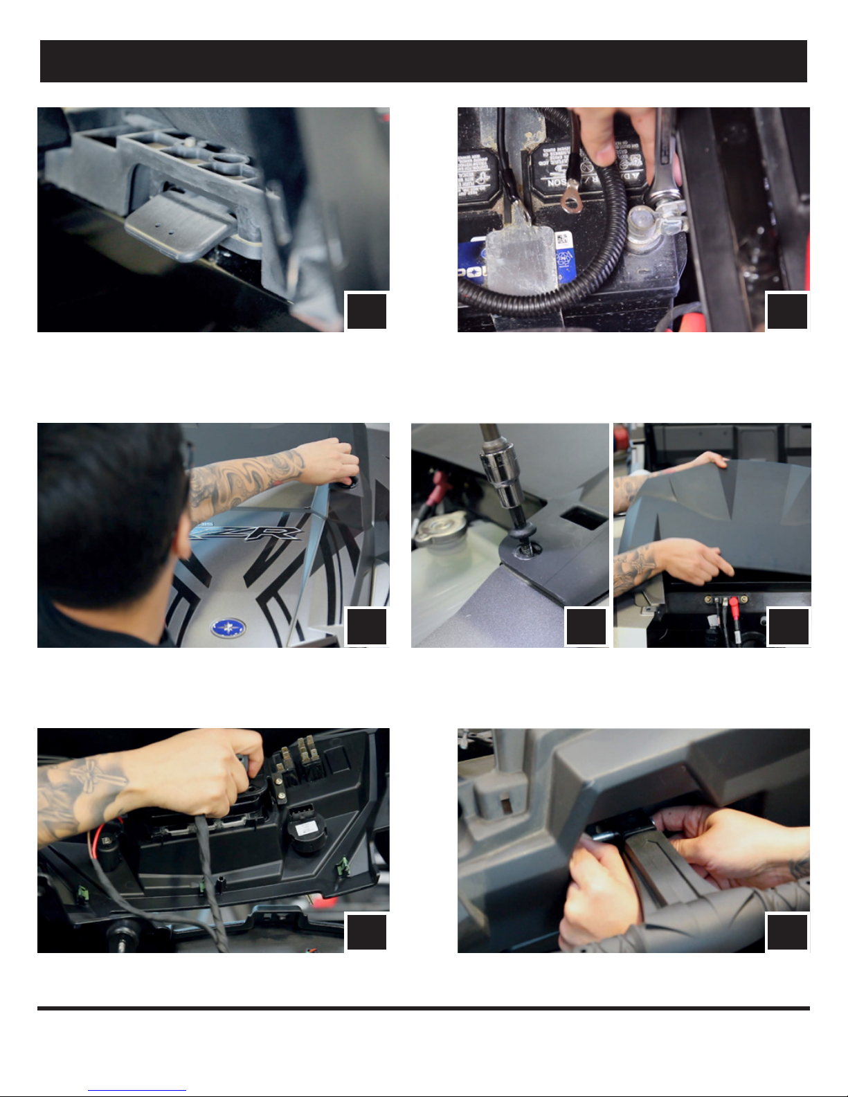
PANELS AND DASH DISASSEMBLY
A. Remove all seats by releasing the handle behind each seat,
push forward slightly while lifting up.
C. Remove hood by turning locking pins and lifting up.
A
C
B
B. Disconect the negative battery cable from the battery.
DD
D. Remove center dash by unscrewing the 2 T-30 Torx screws and push center
dash forward to unclip.
E. Disconnect all harness connectors attached to the center dash panel.
E
F. Un-pin and pull to remove the passenger side safely handle.
F
4
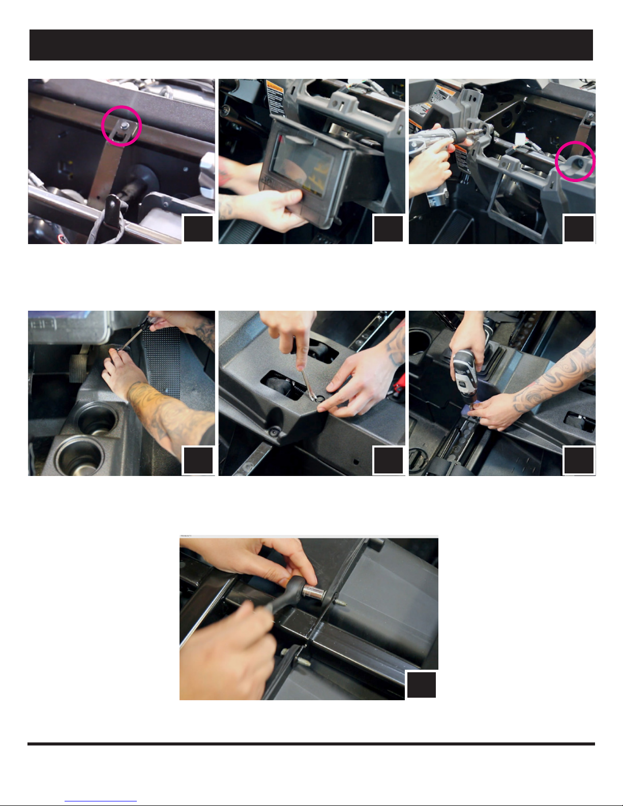
PANELS AND DASH DISASSEMBLY
G1
G. Remove the factory dash pocket by rst extracting the 10mm bolt on the dash frame (G1). Then pull out the dash pocket with bracket attached (G2) - NOTE
this bracket will no longer be used for any part of this installation. Save this screw as it will be use later during the amp plate installation.
Extract (2) screws securing the sub dash (G3). Unsnap and remove.
H
H. Remove all of the center console push pins and T-30 Torx screws. For 4-seat models, disconnect the harness attached to the 12v accessory socket.
G2
H
G3
H
I. Remove glovebox by removing (2) 10mm screws.
I
5
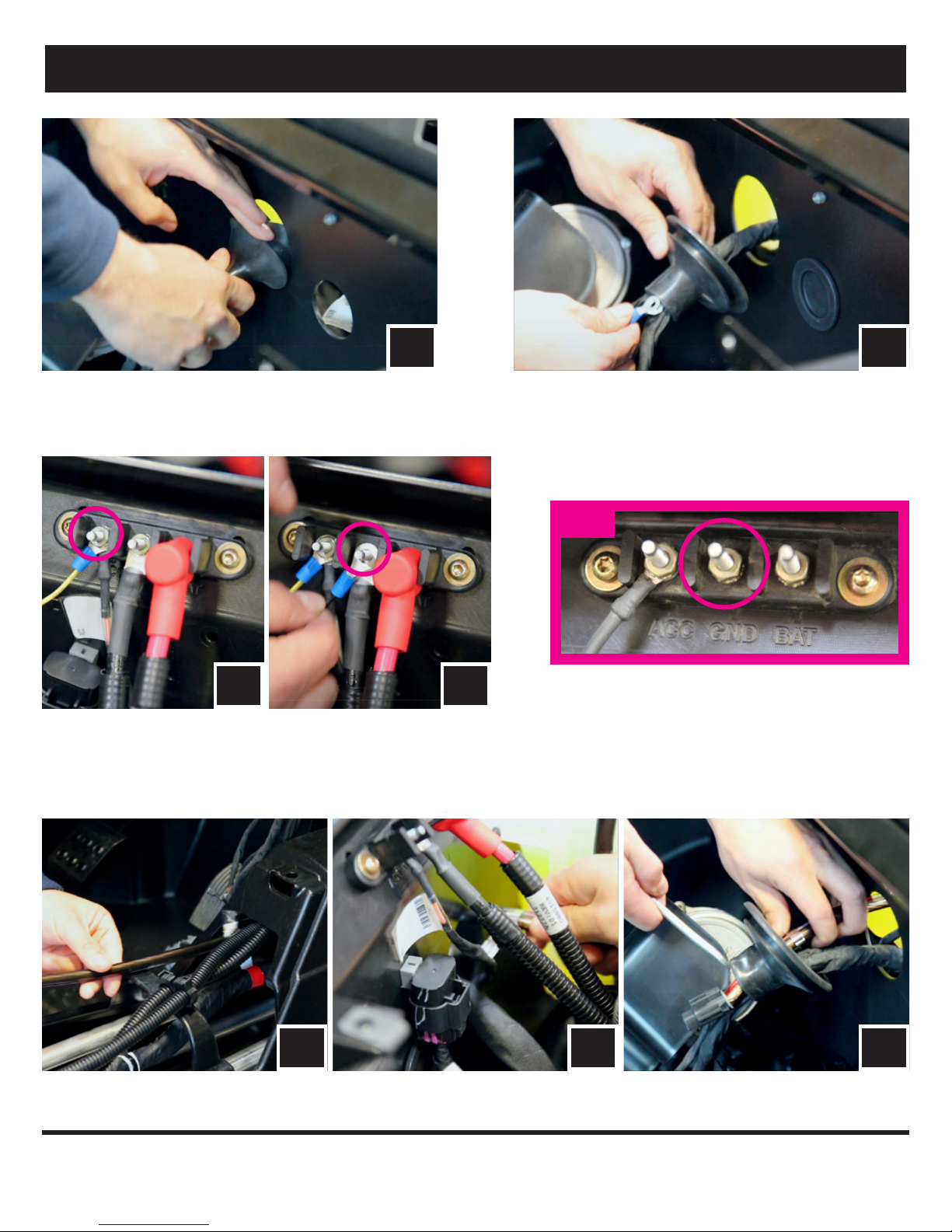
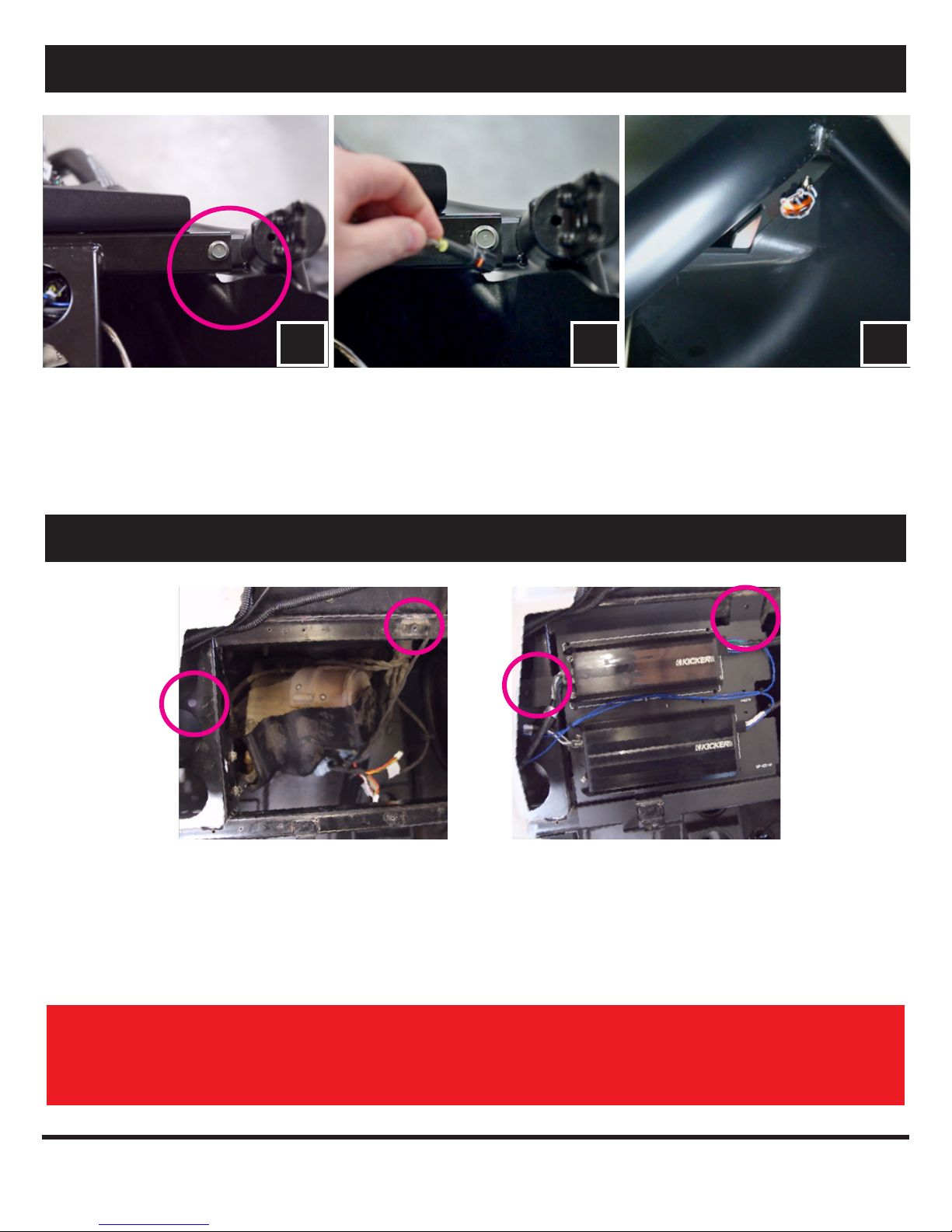
RUNNING AMP POWER CABLE AND REAR SPEAKER WIRE
BA
A. Unwrap the tape and pull the rubber wire grommet out of the rewall.
C. From under the hood, against the top rewall, unscrew the nut on the rst
position terminal (12v accessory) and attach the yellow POWER wire. Refasten
on the nut (C1). Then unscrew the nut on the second position terminal and
attach the black GROUND wire. Re-screw on the nut (C2).
B. Pull the MRB3 POWER and GROUND wires through the rubber
grommet and feed through the hole in the rewall to the power strip
located on the opposite side of the rewall.
NOTE
C2C1
Some RZR models come with the ground “GND” terminal not
connected as shown. If you do not have a factory wiring going to
this terminal, add a ground wire from the “GND” terminal to the
frame before connecting the wires. We recommend removing
the paint to bare metal, using a star washer, and repainting over
the connection.
D1 D2 D3
D. Feed the connector end of the Amp power wire through the center console to the other side of the rewall (D1). Then feed the power wire through the grommet
hole (D2) and through the rubber grommet with the rest of the vehicle’s wiring and cables (D3). Do the same for the 2nd Amp power & rear speaker wire.
6
RUNNING AMP POWER CABLE AND REAR SPEAKER WIRE
E E E
E. Route the front speaker wire through the opening where the rewall and roll
cage bar meet on both the driver and passenger side. Leave these wires loose
until the front speaker pods are to be installed.
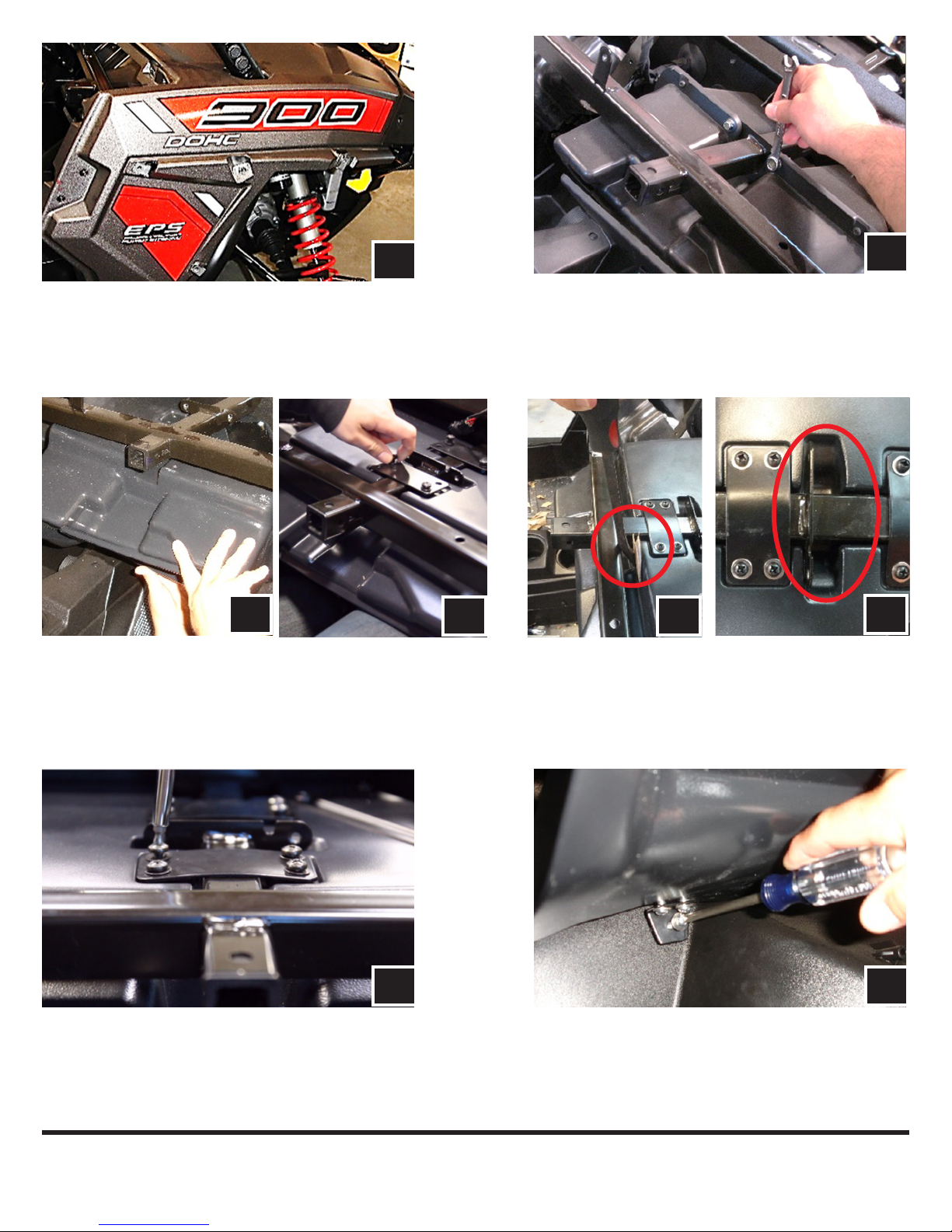
AMP PLATE INSTALLATION
2
TOP VIEW
UNDERNEATH VIEW
11
2
Place the pre-installed amp plate with MRB3 Brain on the frame of the dash and line up the hole on the top
of the amp plate to the factory hole where the pocket bracket was previously installed (1). Loosely screw in
the factory 10mm screw in this hole location that was previously removed.
Next loosely screw in the M6 screw with washer from underneath the steering column into the amp plate (2).
Lastly hand tighten both screws.
THIS CONCLUDES THE DISASSEMBLY AND RUNNING OF THE POWER AND SPEAKER WIRE. NOW
REFER TO INSTRUCTION 1 - INSTALLATION OF THE GLOVEBOX SUBWOOFER ENCLOSURE.
7

8

RZR XP1000 & 2015+ RZR900
Kicker 10” Glove Box
Subwoofer Enclosure
WARRANTY INFORMATION:
All SSV Works enclosures are covered by a limited lifetime warranty against defects in material or
workmanship. All SSV Works Electronics are covered by a limited 1 year warranty against defects
in material or workmanship. All Kicker Speakers are covered by a limited 1 year warranty against
defects in material or workmanship. All Kicker Ampli ers are covered by a limited 2 year warranty
against defects in material or workmanship. Labor for replacement of defective components is not
covered. Contact SSV Works for further warranty information.
TOOLS NEEDED FOR INSTALLATION
- Wire Crimpers
- Wire Strippers
- 10mm Socket or Wrench
- Drill with 1/8” and 1/4” Drill bits
- T-30 Torx Driver
- T-40 Torx Driver
- #3 Phillips Screwdriver
- #2 Phillips Screwdriver
- Panel removal tool
PARTS LIST IMAGES
!
Please read and understand these
instructions completely before
installation to avoid possible injury, or
damage to the accessory or vehicle.
1. WP-RZ3GBS10 Enclosure
(door not included)
5. Flat Mounting
Brackets x 2
2. M6 x 16mm Screws x 11
6. “L” Bracket x 1
INSTALLATION NOTES
Removal of the passenger fender is not required (Step 3); however it will make the installation and alignment of the RZ3-GB10K easier.
(Long)
3. M6 x 8mm Screws x 2
(Short)
7. Glove Box Door
Bracket x 1
4. M6 Washers x 13
8. H1173 Audio Cable
9
A
B
A. Remove the ten T40 Torx bolts that secure the 2 piece fender.
Note: there is one screw inside the fender well. Remove the
two additional screws from the striker plate, slide fender up
the cage rail and secure
C D
C. Lift the enclosure into place and align the top channel in the grab handle
bar. While holding the enclosure in place, loosely attached the fl at brackets
to the top of the enclosure using the long screws provided.
B. Remove the two 10mm bolts that secure factory glove box and
remove the factory glove box
C
D. To properly align the box, slide the box rmly toward the front of
the vehicle. It should sit approximately 1/4” from the factory
glove box mount. If not properly installed, the kick pod and dash
panel will not align in place.
D
E. While applying pressure to keep the enclosure secure against
the front wall, tighten the top brackets, as they tighten they
will bend slightly to add pressure and avoid any vibration, now
tighten the lower L bracket to the enclosure
E
F. Loosely install the bottom L bracket, align the mounting hole with
the factory bung and secure with one of the long screws provided
(you will tighten the bracket to the enclosure and factory bung
AFTER step J)
F
10
 Loading...