

SSV Works PHASE 5 X3-5K, PHASE 5 X3-DM3, PHASE 5 US-C65K, PHASE 5 X3-US10K, PHASE 5 X3-F4 User Manual
Page 1
PHASE
5
®
®
MAVERICK X3
CAN-AM
pg 3
POWERSPORTS AUDIO KIT
Disassembly, Wire and
Amplier Plate Installation
pg 11
Dash Kit Installation
pg 15
Underseat Subwoofer
Installation
pg 19
Dash Speaker Pods
Installation
pg 23
Cage Mount Speaker Pods
Installation
Page 2

2
Page 3

X3-5K
Can-Am Maverick X3 & X3 Max
Kicker 5 Speaker Audio Kit
WARRANTY INFORMATION:
All SSV Works enclosures are covered by a limited lifetime warranty against defects in
material or workmanship. All SSV Works Electronics are covered by a limited 1 year warranty
against defects in material or workmanship. All SSV Works Speakers are covered by a
limited 1 year warranty against defects in material or workmanship. Labor for replacement of
defective components is not covered. Contact SSV Works for further warranty information.
!
TOOLS NEEDED FOR INSTALLATION WIRE AND CABLE PARTS LIST
- T30 torx
- 10mm wrench or socket
- 13mm wrench or socket
- 18 mm socket with extention
- Wire crimpers
- Panel removal tool
- #2 screw driver
- 1” Uni bit ( for USB/Aux )
- #3 screw driver
1. Amp Power Wire
2. Front B-H1149 Speaker Harness
3. Rear B-H1151 Speaker Expansion
Harness
4. MRB3 Power & Ground Connector
5. Direct-t Amp Plate with pre-tuned
Amp(s) and MRB3 Brain
PARTS LIST IMAGES
Please read and understand these
instructions completely before
installation to avoid possible injury, or
damage to the accessory or vehicle.
6. M6 x 1.0 Screw x 1
7. M6 Washer x 1
8. M6 Nut x 1
9. Zip Ties x
10. WP-H16PG84-6 Harness
1. Amp Power Wire with Fuse
Holder
5. Direct-t Amp Plate with pretuned Amp(s) and MRB3 Brain
8. Zip Ties x 5 10. WP-H16PG84-6 Harness
2. Front B-H1149 Speaker
6. M6 x 1.0 Screw x 1 7. M6 Washer x 1 7. M6 Washer x 1
Harness
3. Rear B-H1151 Speaker
Expansion Harness
4. MRB3 Power & Ground
Connector
3
Page 4
PANELS AND DASH DISASSEMBLY
A
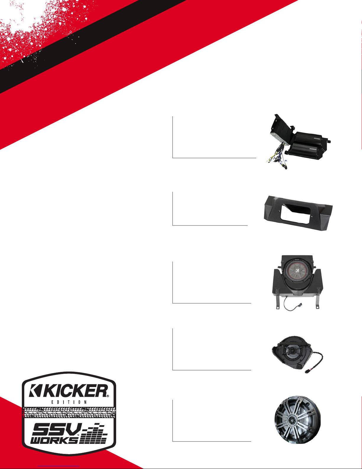
A. To remove the seat, use a 13mm socket and wrench to remove front (2) bolt and nut, and use a 18mm socket to remove (2) rear nuts and seat belt nut
( repeat on other seat)
B B B
B. Carefully unsnap center dash side panels by hand or with a panel removal tool.
A
C. Unscrew (2) T30 torx located on the center console panel under the
dash. Use a panel tool to remove push pins on passenger side.
4
C
D
D. Carefully unsnap rear cover to expose the engine compartment
Page 5
PANELS AND DASH DISASSEMBLY
EE E
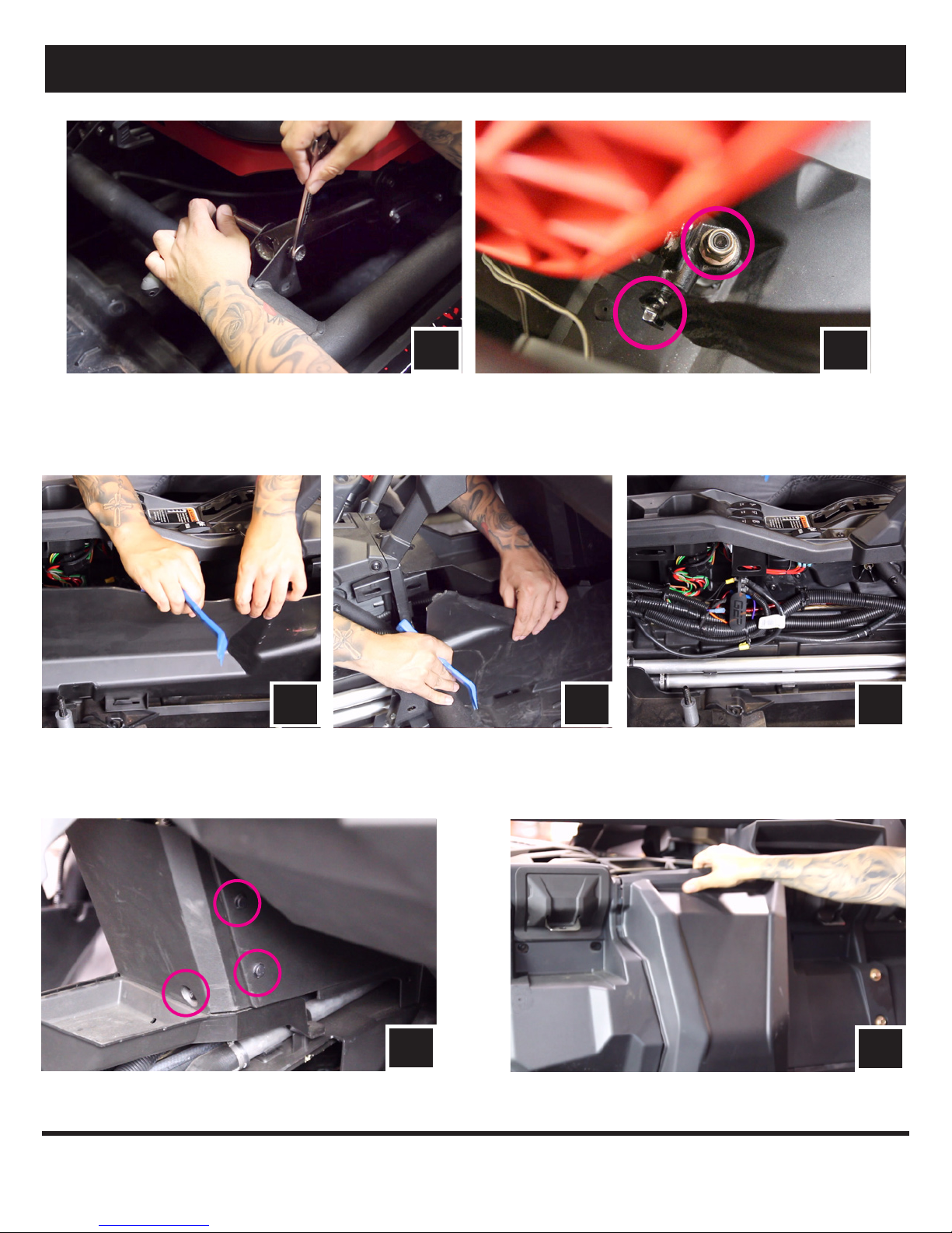
E. Remove gas cover on the passenger side to expose a 10mm nut. Unscrew with a wrench and T30 torx driver.
E2 E2
E2. Using panel removal tool unsnap (2) push clips on the driver and passenger side dash covers. Unscrew the (4) T30 screws on the passenger
side, and (7) T30 screws on the driver side.
F
F. Remove fender well panel using a T30 driver (will need a10mm socket for
the screw near the headlight)
G. After the fender well panel is removed, remove the third fastener clip
from the bottom.
G
5
Page 6
RUNNING AMP POWER CABLE AND SPEAKER WIRE
WP-H16PG84-6
MRB3 Power Connector
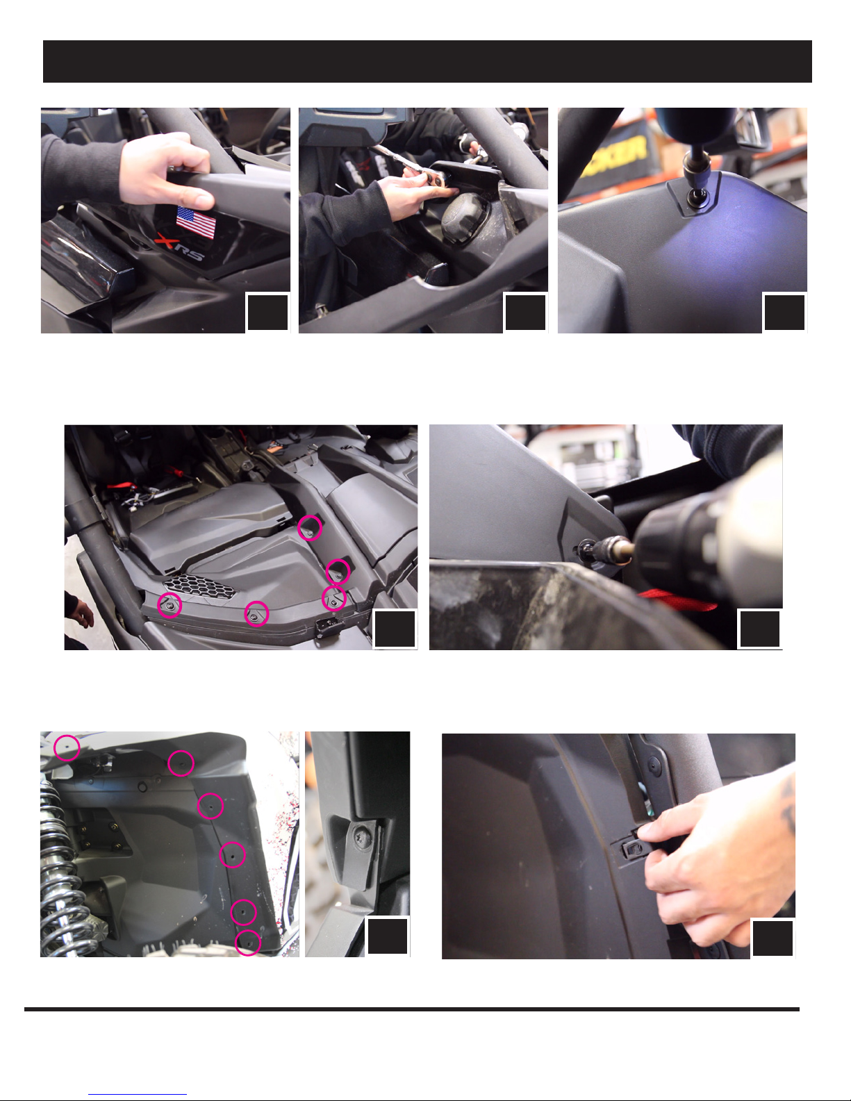
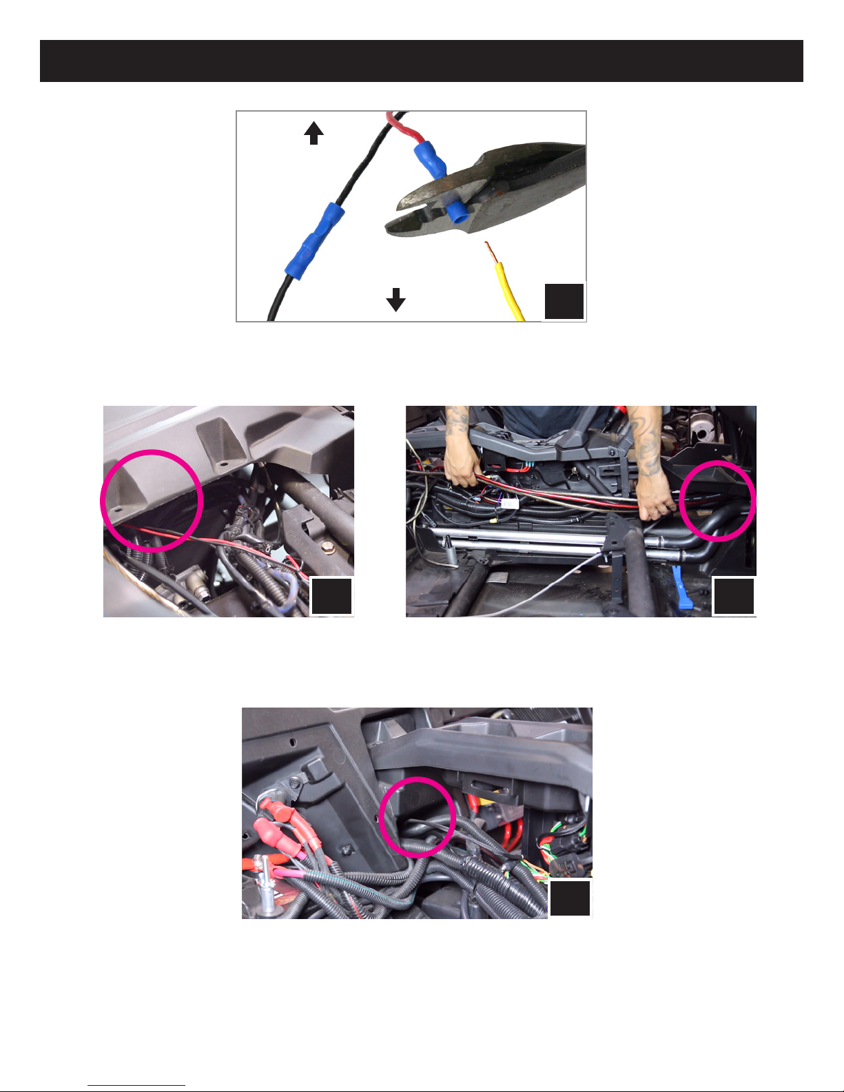
H. Connect the MRB3 Power into the WP-H16PG84-6. Using the butt splice
terminals on the WP-H16PG84-6, connect black to black and red to yellow.
H
I1 I2
I. In this step you will be feeding all of the necessary wires from the top drivers side dash down the center dash column. Be sure to run all of
the wires along side the factory cabling to avoid any moving parts. Feed both amp power wires, rear speaker expansion harness, subwoofer
harness, and power/ground for MRB3 from top driver side down the center column (I1). Pull all wires through the bottom center column and
across the center console with the factory wiring (I2).
J
J. Run rear expansion harness through rear center console cavity, following the
factory cables. If you are installing a 3-speaker kit, simply zip tie the cable
to a factory harness as this step is completed. If installing a 5-speaker kit,
please refer to the installation of the Cage Mounted Speakers.
The connection of each cable will be address further along in the instructions.
6
Page 7
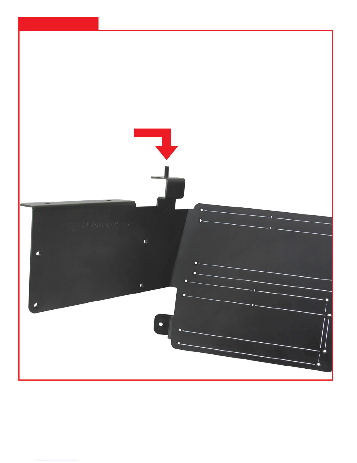
INSTALLATION NOTES
AMP TRAY MODIFICATION WITH USE
WITH AN AFTERMARKET ROLL CAGE
1. REMOVE THIS THREADED
STUD BEFORE INSTALLAION OF
THE AMP TRAY. GENTLY TAP OUT
THE THREADED STUD WITH A
HAMMER. BE CAREFUL NOT TO
BEND THE BRACKET.
2. IF NEEDED, INCREASE THE
DIAMETER OF THE HOLE TO
ACCOMMODATE THE ROLL
CAGE BOLT
7
Page 8

AMP PLATE INSTALLATION
K
K. From underneath driver side place amp plate between the two cross bars behind the steering wheel.
L
L. Make sure the threaded bolt on the amp plate goes through the
factory hole located in the corner where the cage tubing connects.
* If your vehicle is equipped with an aftermarket cage, refer to page 2
for the installion of the amp tray.
M. Secure the amp tray to the vehicle using the supplied M6 nut and
washer.
K
M
N. Make a pilot hole with a pick tool through the top right screw hole in
the amp plate and push all the way through the vehicle panel.
8
N O
O. Drill a larger hole through the pilot hole using a 1/4” drill bit. Be sure
to move the amp plate out of the way before drilling.
Page 9

AMP PLATE INSTALLATION
P1 P2
P. Route the front B-H1149 speaker harness towards the driver and passenger side of the vehicle and leave the 4 pin connector at the driver
side of dash (P1). Route the passenger side speaker wire under the center dash panel all the way to the passenger side speaker location (P2).
Q3Q2Q1
Q. Connect the B-H1149 to the front output of the 300.4 amplifer. Connect the B-H1151 to the rear output of the 300.4 amplier. Connect the B-H1152 to
the output of the 500.1 amplier (Q1). Connect the B-H1221 MRB3 power harness to the MRB3 brain (Q2). Connect both amplier power harnesses to
each amplier (Q3).
R R R
R. Connect the power and ground for the MRB3 brain on the power strip located on the passenger side of the center console. Unscrew the top post, remove
the nut and install the black-ground wire terminal. Replace the nut. Unscrew the center post, remove the nut and install the red-battery power wire
terminal. Replace the nut.
9
Page 10

USB/AUX INPUT PORT INSTALLATION
S. Remove the (4) T30 torx on the front and inside of the glove box
U. Pull up and remove the glove box.
S
U
T
T. Remove push clips from underneath glove box.
V
V. Drill a 1” hole through the left side of the glove box for wiring
W W
W. Unscrew and remove the plastic nut from the port. Make sure to open the fuse
holder and remove the fuse so the nut will t through it. Feed in the wires through
the hole. Keep the fuse holder open and empty until it has passed through the hole.
10
outside viewinside view inside view
X
X. Feed the plastic nut back through the wires and cables and screw
back on to the port. Hand tighten only.
Page 11

SSV WORKS, 201 N. Rice Ave Unit A, Oxnard, CA 93030
www.SSVworks.com | Phone: 818-991-1778 | Fax: 866-293-6751
X3-DM3
Can-Am Commander X3
Dash Kit for MRB3
WARRANTY INFORMATION:
All SSV Works enclosures are covered by a limited lifetime warranty against defects in
material or workmanship. All SSV Works Electronics are covered by a limited 1 year warranty
against defects in material or workmanship. All SSV Works Speakers are covered by a
limited 1 year warranty against defects in material or workmanship. Labor for replacement of
defective components is not covered. Contact SSV Works for further warranty information.
TOOLS NEEDED FOR INSTALLATION PARTS LIST
- #2 Phillips Screw Driver
- 1/8” drill bit
- 1/2” drill bit
- Drill
1. X3-DM3 Base Plate
2. X3-DM3 Top Panel
3. #7 x 1.25 Kit Screws x4
PARTS LIST IMAGES
!
Please read and understand these
instructions completely before
installation to avoid possible injury, or
damage to the accessory or vehicle.
4. M3 x 20mm Screws x2
5. M3 Washers x 2
6. M3 Hex Nuts x 2
1. X3-DM3 Base Plate
3. #7 x 1.25 Kit Screws x4
4. M3 x 20mm Screws x2
INSTALLATION NOTES
For instructions regarding the MRB3 black box, refer to the MRB3 manual.
5. M3 Washers x 2
2. X3-DM3 Top Panel
6. M3 Hex Nuts x 2
11
Page 12

A
B
A. Remove the factory rocker switches.
B. Locate the two dimples at the top of the dash. These dimples
are actual screw bosses on the underside of the dash.
C C C
Line up base plate Drill pilot hole Drill 1/2” hole
C. Rest the X3-DM3 base plate on the dash. Line up the two outside screw holes with the dimples of the dash. Do not screw the kit in yet.
While holding the base plate down to the dash, use the center hole on the base plate to drill your 1/8” pilot hole.
Remove the base plate and open the pilot hole up using a 1/2” drill bit.
D. Place the base plate back on the dash lining up the outside
screw holes to the dimples on the dash. Using (2) #7 Screws and
a philips screw driver secure the base to the dash. Make sure the
screws are driving into the dash dimples for best results.
12
D
E
E. Fasten the MRB3 Remote to the dash kit using (2) M3 screws.
Page 13

F
F. Now that the MRB3 remote is mounted to the dash kit route the din cable through the base plate so that it drops into the dash.
Pull the din cable all the way through until the X3-DM3 Top Panel rests on the Base Plate.
F
G
G. Using (2) #7 screws, secure the top of the Top Panel to the Base Plate.
H
H. Refer to the MRB3 manual for wiring instructions.
G
13
Page 14

14
Page 15

X3-US10K
SSV WORKS, 201 N. Rice Ave Unit A, Oxnard, CA 93030
www.SSVworks.com | Phone: 818-991-1778 | Fax: 866-293-6751
WARRANTY INFORMATION:
All SSV Works enclosures are covered by a limited lifetime warranty against defects
in material or workmanship. All SSV Works Electronics are covered by a limited 1 year
warranty against defects in material or workmanship. All SSV Works Speakers are
covered by a limited 1 year warranty against defects in material or workmanship. Labor
for replacement of defective components is not covered. Contact SSV Works for further
warranty information.
TOOLS NEEDED FOR INSTALLATION PARTS LIST
- 10mm Socket or Wrench
- T-30 Torx Driver
- T-40 Torx Driver
1. X3-US10 Enclosure
2. B-H1220 Subwoofer
Bridge Adapter
3. M6 x 16mm Screws x 10
4. M6 Washers x 10
PARTS LIST IMAGES
2016+ Can-Am Maverick x3
10” Under Seat Enclosure
Please read and understand these
instructions completely before
!
5. M6 x 25mm
6. Large washers x 2
7. D-Brackets x 2
8. A-Bracket x 1
installation to avoid possible injury, or
damage to the accessory or vehicle.
9. B-Bracket x 1
Screw x 1
10. Seat Risers x 2
11. Small Spacer x 1
12. M6 Locking Hex Nut
13. Foam Strips x 3
1. X3-US10 Enclosure
5. Large washers x 2
9. Seat Risers x 2
Bridge Adapter
6. D-Brackets x 2
10. Small Spacer x 1
2. M6 x 16mm Screws x 10 2. B-H1220 Subwoofer
7. A-Bracket x 1
11. M6 Locking Hex Nut
3. M6 Washers x 10 4. M6 x 25mm Screw x 1
8. B-Bracket x 1
12. Foam Strips x 3
15
Page 16

A
B
A. Apply the foam strips to the inside right, left and top side of
the enclosure.
B. Using the supplied M6 screws and washers, screw the DD-brackets
to the bottom right and left side of the enclosure.
C C C
C. Remove the factory 10mm nut and bolt from the brake line. Place the washer on top of the factory bracket and push the long M6x25mm screw through
the top. Then attach the brake line, spacer, washer and nut. T hen hand tighten.
D. Replace the factory seat bolt spacers with the supplied SSV
Works spacers
16
D
E1
E. Run the brake line along the dedicated channel on the sub enclosure while feeding
the enclosure down under the seat bar (F1). Make any adjustments to the brake
line so the enclosure lays on top of it. Line up the rear enclosure brackets to the
rear seat bolts and press down until the brackets rest on top of the spacers.
E2
Page 17

F1 F2 F3
F. Place B-Bracket to the left side of the enclosure and slide the tab underneath the enclosure. (F1) Line up the 2 screw holes and proceed to hand thread
the M6 screws and washers. Use a T30 Torx bit to tighten screws. Repeat for the right side. (F2) Line up the top of bracket A and B with the holes on
the factory seat brakcet. Screw in the M6 screw with the large washer (F3).
WIRING INSTRUCTIONS
PXA 500.1
Speaker
Output
B-H1152
B-H1220
17
Page 18

18
Page 19

SSV WORKS, 201 N. Rice Ave Unit A, Oxnard, CA 93030
www.SSVworks.com | Phone: 818-991-1778 | Fax: 866-293-6751
X3-F4
2017+ Can-Am Maverick x3 & x3 Max
4” Speaker Dash Pods
WARRANTY INFORMATION:
All SSV Works enclosures are covered by a limited lifetime warranty against defects
in material or workmanship. All SSV Works Electronics are covered by a limited 1 year
warranty against defects in material or workmanship. All SSV Works Speakers are
covered by a limited 1 year warranty against defects in material or workmanship. Labor
for replacement of defective components is not covered. Contact SSV Works for further
warranty information.
TOOLS NEEDED FOR INSTALLATION
- T-30 Torx Driver
- Drill 1/4” Drill bit
- 10mm Wrench or Rachet
- Utility Knife
PARTS LIST
1. X3-F4 Enclosures (1 pair)
2. Acoustic Lens (1 pair)
3. M6 x 1.0 Screws x 4
PARTS LIST IMAGES
!
Please read and understand these
instructions completely before
installation to avoid possible injury, or
damage to the accessory or vehicle.
4. M6 x 25mm Screws x 2
5. M6 Washers x 6
6. 10mm Nut x 2
1. X3-F4 Enclosures
(1 pair)
4. M6 x 25mm Screws x 2
2. Acoustic Lens (1 pair)
5. M6 Washers x 6 6. 10mm Nut x 2
3. M6 x 1.0 Screws x 4
19
Page 20

A
B
A. Remove the top dash panels on the driver (7 screws with 2
clips) and passenger side (5 screws with 2 clips).
C. Using a utility knife, cut off the (4) tabs fl ush to the panel
B. Pry off the (4) clips on the base under the empty space for the
speaker
C1 C2
D. Drill a hole using a 1/4” drill bit at the factory dimple marks (as shown above) on the outside dash panel around the speaker grille.
20
D2D1
Page 21

E F
E. Place the acousic lens on top of the factory grille, line up
the holes and insert the (2) top M6x1.0 (shorter) screws and
washers.
dash panel and speaker pod. Secure screw using washer and
10mm nut. Now fasten the previous (2) M6x1.0 screws.
F. Place the speaker pod under the dash panel and line up the
holes on the speaker pod with the (2) top screws and loosely
mount the pod to the dash panel.
HG
H. Installation is complete. Refer to wiring instruction below.G. Insert the M6x25mm screw by pushing it through the acoutic lens,
WIRING INSTRUCTIONS
PXA 300.4 B-H1149
Front
Speaker
Output
21
Page 22

22
Page 23

SSV WORKS, 201 N. Rice Ave Unit A, Oxnard, CA 93030
www.SSVworks.com | Phone: 818-991-1778 | Fax: 866-293-6751
US-C65K
Universal Cage Mount
6.5” Speaker Enclosures
WARRANTY INFORMATION:
All SSV Works enclosures are covered by a limited lifetime warranty against defects in
material or workmanship. All SSV Works Electronics are covered by a limited 1 year
warranty against defects in material or workmanship. Labor for replacement of defective
components is not covered. All SSV Works Speakers are covered by a limited 1 year
warranty against defects in material or workmanship. Contact SSV Works for further
warranty information.
TOOLS NEEDED FOR INSTALLATION
- 5mm Allen Key - 8mm Open End Wrench
PARTS LIST IMAGES
!
Please read and understand these
instructions completely before
installation to avoid possible injury, or
damage to the accessory or vehicle.
1. US-C65 Enclosures (1 pair)
4. M6 Hex Head Bolts &
Washers x4
2. Dual Mounting Ring
5. M6 Allen Socket Head Bolts
INSTALLATION NOTES
The use of a thread locker is recommended on all screws to prevent loosening due to vibration. It is recommended to
wrap the bag that the clamps come in around the cage before you slide the clamp onto the cage to prevent scratching.
3. Ring Clamp x 4
Adapter x 2
6. M6 Set Screws x 4
& Washers x4
23
Page 24

A B
A. Find the best orientation for the speaker on your bar and
screw in the Set Screws in the OPPOSITE holes of where the
clamp will install into.
B. Loosely install the clamp base to the cage mount pod with the
two (2) M6 hex head bolts and washers, place the cage mount
pod in the desired mounting location on the vehicle. Once the
ring adapter is in the desired position, tighten the two (2) bolts
using a 8mm open wrench.
C C C
C. Place both ring mounting clamps on the cage using the plastic bag to prevent scratching, place the cage mount pod in its nal mounting location and
secure to the clamps using the two (2) M6 allen socket head bolts and washers with a 5mm allen key.
24
Page 25

D. Take the B-H1150 rear speaker harness and plug into the
B-H1151 rear extension harness.
D
E
E. Route the rear speaker harness (B-H1150) along the factory wires in the engine compartment and pull up through the small space between the
bed panel and cage tubing on both passenger and driver sides.
WIRING INSTRUCTIONS
PXA 300.4
B-H1150
B-H1151
Rear
Speaker
Output
E
25
Page 26

CONNECTING POWER & GROUND CABLE TO BATTERY
A
A. Unscrew the factory nut on the negative battery terminal. Install the 2 ground cables to the screw on the ground battery terminal. Re-install
the factory nut.
B
B. Unscrew the factory nut on the positive battery terminal. Install the 2 power cables to the screw on the postive battery terminal. Re-install the
factory nut.
A
B
C. Zip tie all wiring to the factory cables away from any moving parts.
THIS CONCLUDES THE INSTALLATION PROCESS. REPLACE THE FACTORY PANELS AND SEATS.
QUESTIONS? PLEASE CONTACT SSV WORKS AT 818-991-1778 OR EMAIL SUPPORT@SSVWORKS.COM
26
C
© 2017 SSV Works, Oxnard, CA 93030 X3-5A Rev. B 10-25-17
 Loading...