


IGW/400-UAR
T
WLAN Device Serve
r
Hardware Reference
SSV Embedded Systems
Heisterbergallee 72
D-30453 Hannover
Phone: +49 (0)511/40 000-0
Fax: +49 (0)511/40 000-40
E-mail: sales@ist1.de
Manual Revision: 1.4
Date: 2006-01-09
For further information regarding our products please visit us at www.ssv-embedded.de
IGW/400-UART – Content
SSV EMBEDDED SYSTEMS
2
CONTENT
1 INTRODUCTION............................................................................................................... 3
1.1 Block Diagram ..........................................................................................................................3
1.2 Features IGW/400-UART.........................................................................................................3
2 OVERVIEW.......................................................................................................................4
3 COMPONENTS ................................................................................................................5
3.1 14-Pin Environment Interface Connector (EI/O)......................................................................5
3.2 Power LED................................................................................................................................5
3.3 WLAN Activity LED................................................................................................................5
3.4 RS232 Connector (UART1)......................................................................................................5
3.5 Reverse SMA Connector for WLAN Antenna .........................................................................5
3.6 10/100 Mbps Ethernet Interface................................................................................................5
4 MECHANICAL DIMENSIONS ...........................................................................................6
4.1 Mechanical Dimensions with DIN-Rail Mounting Set.............................................................7
4.2 Mechanical Dimensions with Wall Mounting Set ....................................................................8
4.3 Drilling Template for Wall Mounting Set.................................................................................9
5 PIN ASSIGNMENTS ....................................................................................................... 10
5.1 14-Pin Environment Interface Connector (EI/O)....................................................................10
5.2 RS232 Connector (UART1)....................................................................................................10
5.3 10/100 Mbps Ethernet Interface..............................................................................................10
CONTACT .............................................................................................................................11
DOCUMENT HISTORY ......................................................................................................... 11
COPYRIGHT .........................................................................................................................11
IGW/400-UART – Introduction
SSV EMBEDDED SYSTEMS
3
1 INTRODUCTION
The WLAN Device Server IGW/400-UART integrates typical measurement and control
interfaces into an IEEE 802.11b/g-compatible WLAN/WiFi Network.
This very compact system acts as small, easy to use interface converter, which collects
any data of industrial automation components and transmits it via IEEE 802.11-based
WLAN.
This document describes the hardware components of the IGW/400-UART. For further
information about the individual components of this product you may follow the links
from our website at http://www.ssv-comm.de.
Our website contains a lot of technical information, which will be updated in regular
periods.
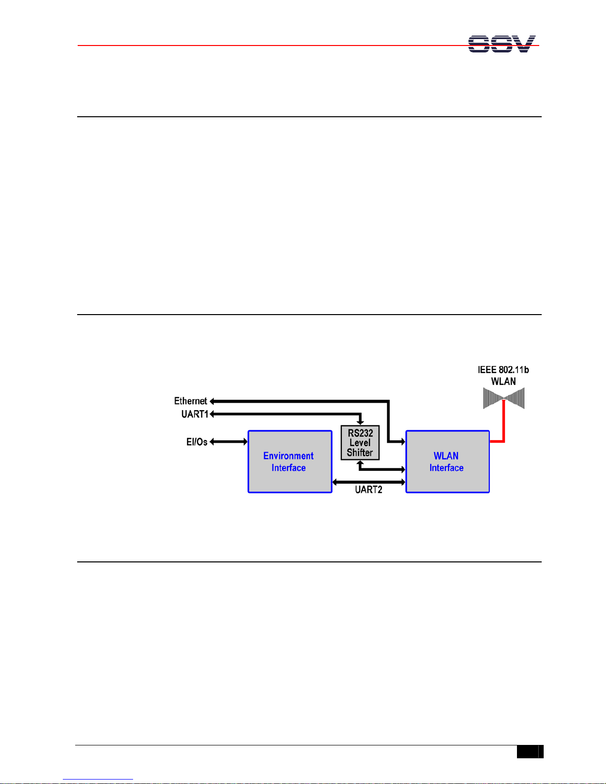
1.1 Block Diagram
Figure 1 shows the block diagram of the IGW/400-UART. UART1 correlates with the
RS232 connector (UART1) and the EI/Os correlate with the 14-pin environment interface
of the IGW/400-UART.
Figure 1: Block diagram of IGW/400-UART
1.2 Features IGW/400-UART
• One 14-pin environment interface connector (EI/O) with RS232/RS422
• One 10/100Mbps Ethernet interface (LAN)
• One RS232 connector (UART1)
• One reverse SMA connector for WLAN antenna
• One power LED (green)
• One WLAN activity LED (red)
• Supply voltage 6 - 30 VDC
• Size 131 x 70 x 26 mm (without antenna)
IGW/400-UART – Overview
SSV EMBEDDED SYSTEMS
4
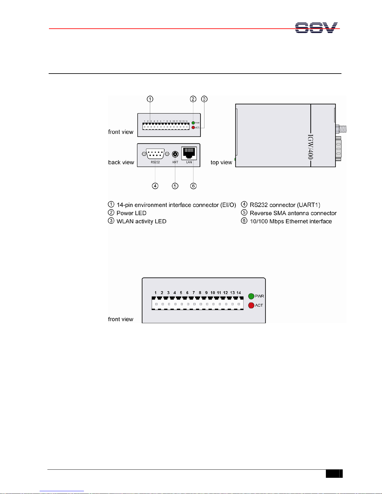
2 OVERVIEW
Figure 2: Overview IGW/400-UART
IGW/400-UART – Components
SSV EMBEDDED SYSTEMS
5
3 COMPONENTS
This chapter describes the components of the IGW/400-UART shown in chapter 2 and
gives a short overview about their respective functions.
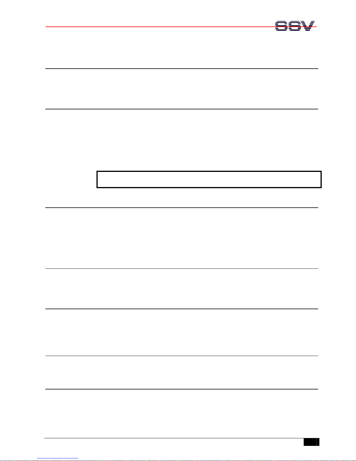
3.1 14-Pin Environment Interface Connector (EI/O)
The environment interface connector is used to connect the power supply unit via the
power supply adapter cable to the pins 1 and 2 of the environment interface. The
IGW/400-UART needs a supply voltage of 6 - 30 VDC to work.
Furthermore it is possible to create a RS232 (pins 3 - 8) and a RS422 (pins 10 - 13)
connection with the Sub-D adapter cable. Please refer to chapter 5.1 for the complete
pinout.
Caution: Providing the IGW/400-UART with a supply voltage higher than 30 VDC
could damage the IGW/400-UART!
3.2 Power LED
The green power LED indicates a present supply voltage. This LED is on when the
IGW/400-UART is provided with a voltage of 6 - 30 VDC by the power supply. If this
LED is off, check the connection between the power supply and the IGW/400-UART.
Check also if the power supply is set to 6 - 30 VDC. The default setting of the power
supply is 12 VDC.
3.3 WLAN Activity LED
The red WLAN activity LED indicates activity on the WLAN interface. If this LED is
off, check the WLAN connection settings of the IGW/400-UART.
3.4 RS232 Connector (UART1)
The IGW/400-UART is equipped with a standard RS232 connector named UART1. This
interface comes with a 9 pin Sub-D male connector. The pin assignment of UART1 is
identical to the COM port assignment of a PC, so it is possible to use a null-modem cable.
3.5 Reverse SMA Connector for WLAN Antenna
The reverse SMA connector is used to attach the WLAN antenna to the IGW/400-UART.
3.6 10/100 Mbps Ethernet Interface
The IGW/400-UART allows Ethernet connectivity with a speed up to 100 Mbps. The
LAN interface of the IGW/400-UART is a standard RJ45 Ethernet interface. The LAN
interface is an alternative to the WLAN antenna. You cannot use the LAN interface and
the WLAN antenna at the same time.

IGW/400-UART – Mechanical Dimensions
SSV EMBEDDED SYSTEMS
6
4 MECHANICAL DIMENSIONS
All length dimensions have a tolerance of 0.5 mm.
Figure 3: Mechanical dimensions of IGW/400-UART

IGW/400-UART – Mechanical Dimensions
SSV EMBEDDED SYSTEMS
7
4.1 Mechanical Dimensions with DIN-Rail Mounting Set
All length dimensions have a tolerance of 0.5 mm.
Figure 4: Mechanical dimensions of IGW/400-UART with DIN-rail mounting set

IGW/400-UART – Mechanical Dimensions
SSV EMBEDDED SYSTEMS
8
4.2 Mechanical Dimensions with Wall Mounting Set
All length dimensions have a tolerance of 0.5 mm.
Figure 5: Mechanical dimensions with wall mounting set

IGW/400-UART – Mechanical Dimensions
SSV EMBEDDED SYSTEMS
9
4.3 Drilling Template for Wall Mounting Set
All length dimensions have a tolerance of 0.5 mm.
Figure 6: Drilling template for wall mounting set

IGW/400-UART – Pin Assignments
SSV EMBEDDED SYSTEMS
10
5 PIN ASSIGNMENTS
5.1 14-Pin Environment Interface Connector (EI/O)
Pin Name Function
1 Vin 6 - 30 VDC power input
2 GND Ground
3 DCD2 (RS232) UART2 RS232 serial port, DCD2 pin
4 RXD2 (RS232) UART2 RS232 serial port, RXD2 pin
5 TXD2 (RS232) UART2 RS232 serial port, TXD2 pin
6 DTR2 (RS232) UART2 RS232 serial port, DTR2 pin
7 RTS2 (RS232) UART2 RS232 serial port, RTS2 pin
8 CTS2 (RS232) UART2 RS232 serial port, CTS2 pin
9 GND Ground
10 TX+ (RS422) UART2 RS422 serial port, TX+ pin
11 TX- (RS422) UART2 RS422 serial port, TX- pin
12 RX+ (RS422) UART2 RS422 serial port, RX+ pin
13 RX- (RS422) UART2 RS422 serial port, RX- pin
14 Vout 3.3 VDC Output (max. 100 mA)
Table 1: Pinout environment interface
5.2 RS232 Connector (UART1)
Top view Pin Name Function
1 DCD1 UART1 serial port, DCD pin
2 RXD1 UART1 serial port, RXD pin
3 TXD1 UART1 serial port, TXD pin
4 DTR1 UART1 serial port, DTR pin
5 GND Ground
6 --- Not connected
7 RTS1 UART1 serial port, RTS pin
8 CTS1 UART1 serial port, CTS pin
9 --- Not connected
Table 2: Pinout RS232 connector (UART1)
Note: All UART1 port signals are on RS232 level. There is no TTL level available on UART1.
5.3 10/100 Mbps Ethernet Interface
Top view Pin Name Function
1 TX+ 10/100 Mbps LAN, TX+ pin
2 TX- 10/100 Mbps LAN, TX- pin
3 RX+ 10/100 Mbps LAN, RX+ pin
4 --- Not connected
5 --- Not connected
6 RX- 10/100 Mbps LAN, RX- pin
7 --- Not connected
8 --- Not connected
Table 3: Pinout 10/100 Mbps Ethernet interface

IGW/400-UART – Contact
SSV EMBEDDED SYSTEMS
11
CONTACT
SSV Embedded Systems
Heisterbergallee 72
D-30453 Hannover / Germany
Phone: +49 (0)511/40 000-0
Fax: +49 (0)511/40 000-40
E-mail: sales@ist1.de
Internet: www.ssv-embedded.de
DOCUMENT HISTORY
Revision Date Remarks Name
1.0 2005-04-07 first version WBU
1.1 2005-09-22 errors corrected, chapter 2 modified WBU
1.2 2005-09-29 chapters 4.1, 4.2 and 4.3 added WBU
1.3 2006-01-09 errors corrected WBU
COPYRIGHT
The content of this document can change any time without announcement. There is taken
over no guarantee for the accuracy of the statements. The user assumes the entire risk as
to the accuracy and the use of this document. Information in this document is provided
‘as is’ without warranty of any kind. Some names within this document can be
trademarks of their respective holders.
© 2006 SSV EMBEDDED SYSTEMS. All rights reserved.
 Loading...